M.2 ATTACHED ON TOP (HAT)FOR RASPERRY PIM.2 HAT Technical Specifications & User Manual
Purpose of the Document
The purpose of this document is to explain the technical specifications and manual for using the M.2 HAT for Raspberry PI .
Document History
| Version | Author | Date | Description |
| A | 5G HUB | 04.02.2021 | Initial Document |
Package Content
M.2 HAT for Raspberry P Form Factor:
- Raspberry PI HAT for M.2 form factor.
Download
Download and Install LTE&GNSS modem driver for Windows OS: https://github.com/5ghub/5G-NB-IoT/tree/master/DriverDownload and Install QNavigator and QCOM tools for Quectel BG95 here: https://github.com/5ghub/5G-NB-IoT/tree/master/Tools
General Description
Overview
The Raspberry Pi (RP) model B+ can be used with add-on boards called HAT (Hardware Attached on Top). A HAT is an add-on board for RP model B+ that conforms to a specific set of rules that will make life easier for users and enable use of different M.2 form factor and hardware LTE Cat 6/Cat 8/Cat 12 chipsets (EM06, EM12) with raspberry PI.
The RP HAT is a rectangular board (65x56mm) that has four mounting holes in the (nicely rounded) corners that align with the mounting holes on the RP B+, has a 40W GPIO header and supports the special autoconfiguration system that allows automatic GPIO setup and driver setup. The automatic configuration is achieved using 2 dedicated pins (ID_SD and ID_SC) on the 40W B+ GPIO header that are reserved for an I2C EEPROM. The EEPROM holds the board manufacturer information, GPIO setup and a thing called a “device tree” fragment – basically a description of the attached hardware that allows Linux to automatically load the required drivers.
1) via the GPIO connector the HAT can supply a minimum of 1.3A continuously to the Pi.
Key Features
The HAT has following features:
- Has M.2 interface can be used with LTE Cat 6/Cat 8/Cat 12 modules (EM06/EM12)
- Fully compatible with Raspberry Pi models that have the 40-pin GPIO header (4, 3, 2, B+, A+, Zero)
- Easy-to-use, simple setup, plug-and-play
- QMI and PPP are supported
- Clip-in M.2 socket compatible with worldwide LTE/UMTS/HSPA+ and GSM/GPRS/EDGE coverage with regional or global modules which work with different frequencies & carriers
- With the 4G/LTE module (e.g Quectel EM06 and EM12) you can reach 600Mbps downlink and 150Mbps uplink data rates.
- With 4G/LTE modules that supports Carrier Aggregation (CA)
- Dual nano USIM card sockets can easily reachable on the upside and downside of the HAT and switching between the two SIM cards.
- Can be used standalone with PC/Laptop over micro USB, without stacking with Raspberry Pi
- The HAT can be powered from an external 5V source by exposed power pins, directly from Raspberry Pi 5V GPIO headers, via micro USB, or optional JST connector on the bottom of the board
- HAT can provide adjustable 3.3V or 3. V to the M.2 socket.
- M.2 socket and GPIO support I2C.
- The power of the whole board electronics can be disabled for low-power consumption use cases
- The modules (EM06, EM12) have built-in GNSS(GPS/GLONASS) receiver for geo-location applications
- Uses a GPIO connector that spaces the HAT at least 8mm from the Pi (i.e. uses spacers 8mm or larger)
- Conforms to the RP HAT requirements
- Conforms to the HAT mechanical specification
Interfaces
- M.2 interface
- USB 2.0 with High Speed up to 480Mbps
- Dual nano USIM card slot
- 40W GPIO to the raspberry PI
Software Features
The HAT does not need or has a driver. Rather The host computer (such as RPi) needs the driver of the compatible module that will be used with the HAT. For example, if you are using Quectel EM06/EM12 with the HAT, then your host device should have the driver for Quectel modules. Nowadays, most of the Linux kernel comes with the required drivers installed as a result the modules are recognized. The HAT is compatible with the following boards. Note that the HAT can be connected to these board via the USB.
- Raspberry Pi 4, 3, 2, B+, A+, Zero
- Asus Tinker Board
- Rock 64*
- Orange Pi*
- Samsung ARTIK’s Eagleye board
- Latte Panda
General Features
- Temperature Range: -40°C ~ +80°C
- Dimensions: 65 mm x 56 mm x 9 mm
- Weight: Approx. 12g
- Supply Voltage: 3.3V – 5V.
Key Applications
- Environmental sensing and monitoring
- Traffic monitoring
- Video/Music Streaming
- Large Data Downloads and Uploads
- LTE Dongle/Router
- Mobile Internet Hotspot
- GPS Tracking
- Security & Asset tracking
- Smart city, smart building, smart transportation, and smart agriculture.
- Smart Parking
Overview Diagrams
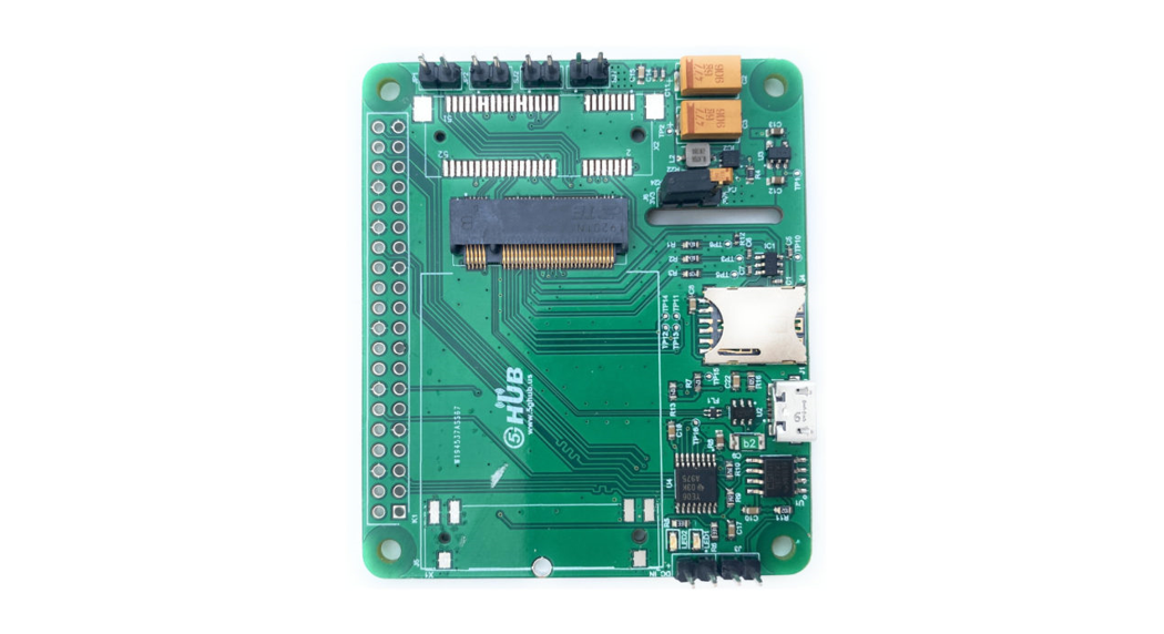
Figure 1. HAT Top View.
Figure 2. HAT Bottom View.
M.2 HAT and GPIO Interface to RASPBERRY PI
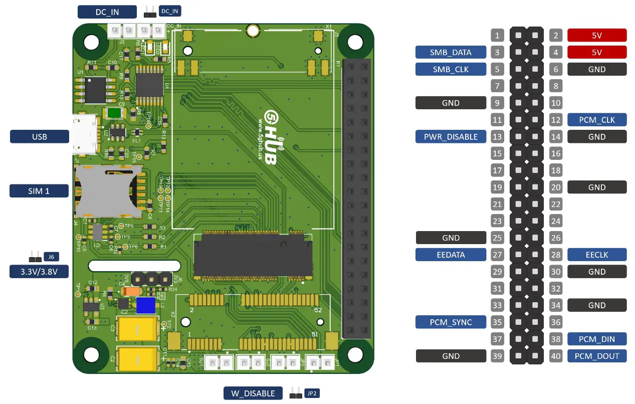 Figure 3. M.2 HAT Top View. Figure 4. M.2 HAT Bottom View.
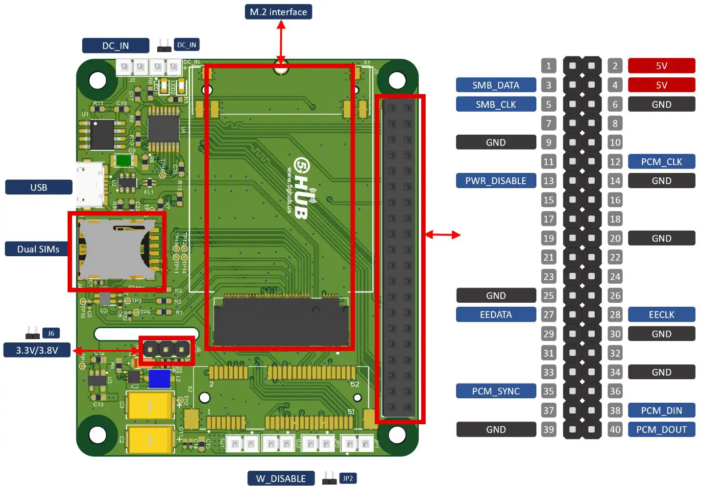
M.2 HAT Pin Diagram and Assignment
The HAT has M.2 socket. The physical connections and signal levels of the M.2 socket complies with M.2 card electromechanical specification and has the following interfaces:
- Power supply
- Dual (U)SIM interface
- USB interface
- PCM and I2C interfaces
- 40 Pin GPIOs for Raspberry Interface
The M.2 socket accepts M.2 cards and has the following signals:
M.2 Pin Description
Table 1: PIN Assignments
|
Pin # |
Pin Name | Pin Direction | Pin Functionality |
|
1 |
NC | ||
|
2 |
VCC 3V3– | 1 | 3.0V-4.4V, typically 3.3V DC supply |
|
3 |
GND | ||
| 4 | VCC | I |
Mini card ground |
| 5 | GND | ||
|
6 |
FULL CARD POWER OFF# | I | VCC |
| 7 | USB DP | 10 |
USB differential data (+) |
|
8 |
W DISABLE1# | 1 | Airplane mode control |
| 9 | USB DM |
10 |
USB differential data (-) |
|
10 |
WWAN_LED# | OD | LED signal for indicating the network status of the module |
| 11 | GND | ||
|
12-19 |
Notch | ||
| 20 | PCM CLK |
10 |
PCM clock signal |
|
21 |
NC | ||
|
22 |
PCM IN | 1 | PCM data input |
| 23 | NC |
OD |
|
|
24 |
PCM OUT | 0 | PCM data output |
| 25 | DPR |
DI |
Dynamic power reduction.High level by default. |
|
26 |
NC | DI | |
|
27 |
GND | ||
| 28 | PCM_SYNC | 10 |
PCM data frame synchronization signal |
|
29 |
NC | ||
|
30 |
USIM1 RESET | 10 |
(U)SIM1 card reset |
| 31 | NC | ||
|
32 |
DO | (U)SIM1 cardclock | |
| 33 | GND | GND | |
|
34 |
USIM1 DATA | 10 | (U)SIM1 card data |
|
35 |
NC | ||
| 36 | USIM1 VDD | PO |
Power supply for (U)SIM1 card |
|
37 |
NC | ||
|
38 |
NC | ||
| 30 | GND | ||
|
40 |
NC | ||
|
41 |
NC | ||
| 42 |
USIM2 DATA |
10 |
(U)SIM2 card data |
|
43 |
NC | ||
|
44 |
USIM2 CLK | DO | (U)SIM2 card clock |
|
45 |
GND | ||
| 46 | USIM2 RESET | DO |
(U)SIM2 card reset |
| 47 | NC |
|
48 |
USIM2 VDD | PO | Power supply for (U)SIM2 card |
| 49 | NC | ||
|
50 |
NC | ||
|
51 |
GND |
||
| 52 |
NC |
||
|
53 |
NC | ||
| 54 |
NC |
||
|
55 |
NC | ||
| 56 |
I2C SDA — |
10 |
12C serial data. Used for external codec |
|
57 |
GND | ||
| 58 | 12C SCL
— |
DO |
12C serial clock. Used for external codec |
|
59 |
NC | ||
|
60 |
RESERVED |
||
| 61 |
NC |
||
| 62 |
RESERVED |
||
|
63 |
NC | ||
| 64 |
RESERVED |
||
|
65 |
NC | ||
|
66 |
NC |
||
| 67 |
RESET# |
DI | System reset. Active low. |
|
68 |
NC | ||
| 69 |
NC |
||
|
70 |
VCC | ||
|
71 |
GND | ||
| 72 |
VCC |
||
|
73 |
GND | ||
| 74 |
VCC |
||
|
75 |
NC |
Switching between Two SIM Card
report this adThe M.2 HAT has dual SIM card slots which provides great benefits to use two SIM cards fromdifferent mobile operator networks to connect to the cellular network. To switch or use one of the SIM card, use the following AT commands on the EM06 and EM12 modules.
Table 2: AT Command for Dual SIM operations (EM06 module).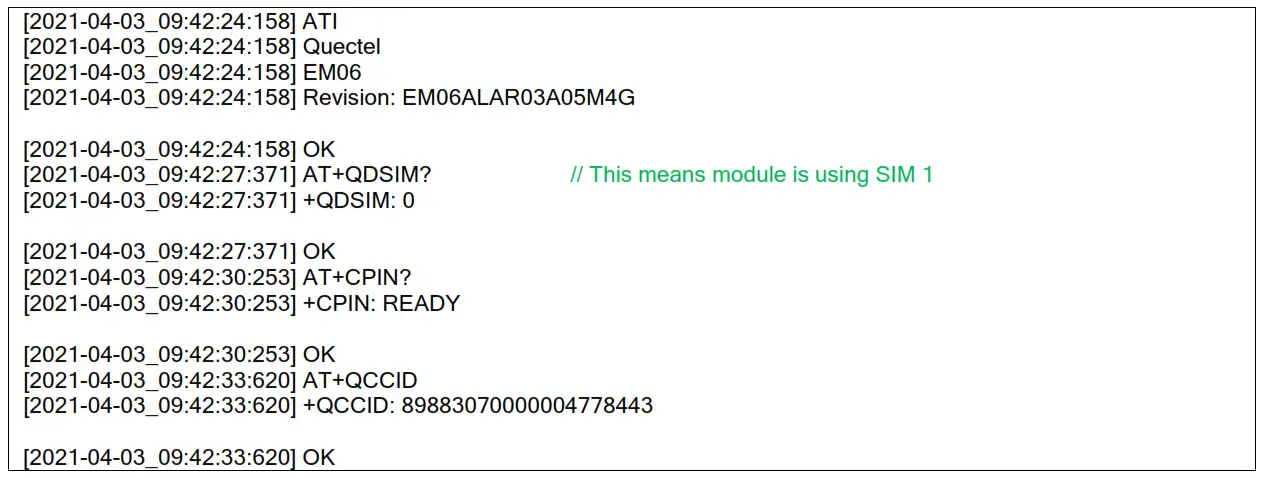
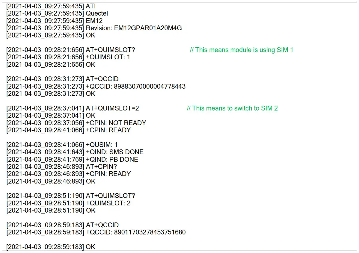 Table 3: AT Command for Dual SIM operations (EM12 module).
References
[xyz-ips snippet=”download-snippet”]