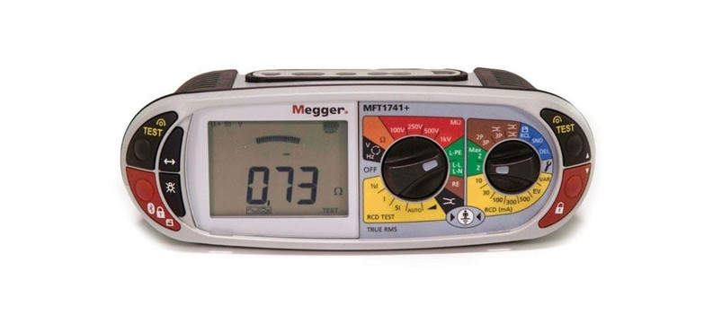
MFT70Quick Start Guide
 5 Commonwealth AveWoburn, MA 01801Phone 781-665-1400Toll-Free 1-800-517-8431
Visit us at www.TestEquipmentDepot.com
MEASURING VOLTAGE

3 Press either TEXT button
 When connecting to a live circuit, the voltage and frequency of supply is automatically displayed.
TEST THE PAIR FOR ALTERNATING CURRENT AND DIRECT CURRENT VOLTAGE
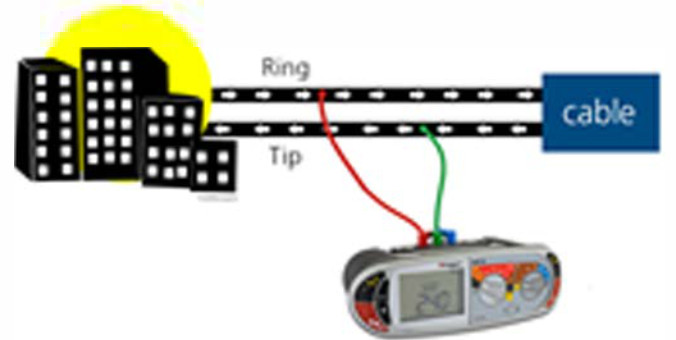

TIP to RING


RING to GROUND
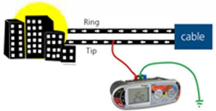

TIP to GROUND
For all 3 setup configurations:


MEASURING CONTINUITY


![]()
![]()
MEASURING INSULATION RESISTANCE
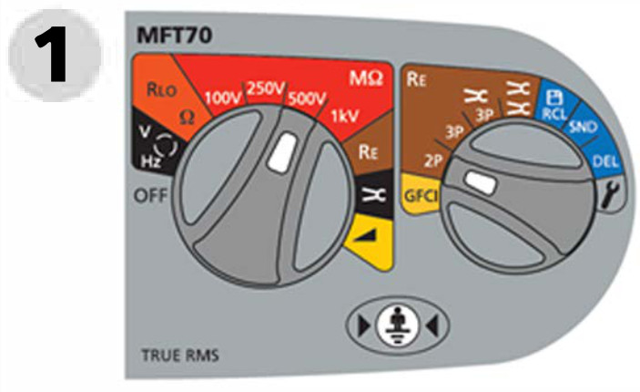


3 Press and hold TEST button
To lock the test, hold down either TEST button, followed by either of the RED lock buttons below.There’s a 500VDC MAX Insulation Resistance Voltage Testing as per Telecom Standards! The field pair must be OPEN at end of loop to properly conduct an insulation resistance test.
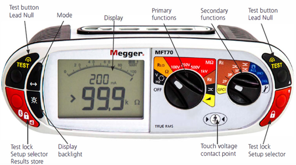

To store your test results:
- Press lock & release
- Using the right test/lock buttons, scroll until the test you need is reached.
- Press lock & release again to display the remaining options & use the right buttons (above) to scroll again.
- Press lock & hold until ‘Str Ok’ is displayed.
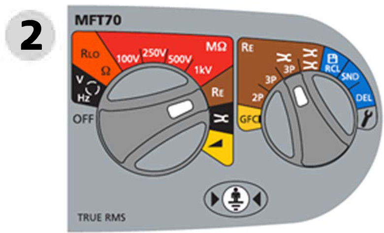
MEASURING GROUND RESISTANCE
2-CLAMP STAKELESS
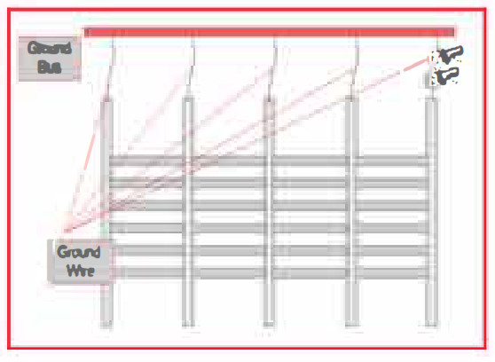
Testing Unbalance in Central Office, Hubs, and Head Ends
1 Set the left rotary switch to OFF
2

Close the current clamp and then the voltage clamp around the conductor under test.Make sure there’s a minimum separation of 100 mm (4 inches) between the current and voltage clamp.
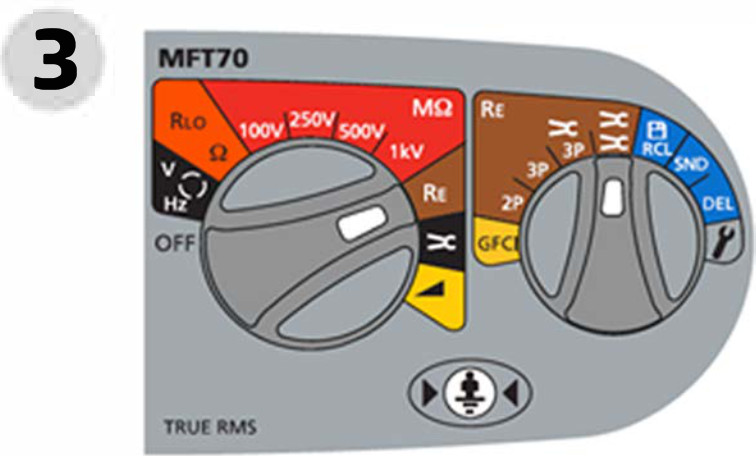

4 Press TEST and release
2-POLE
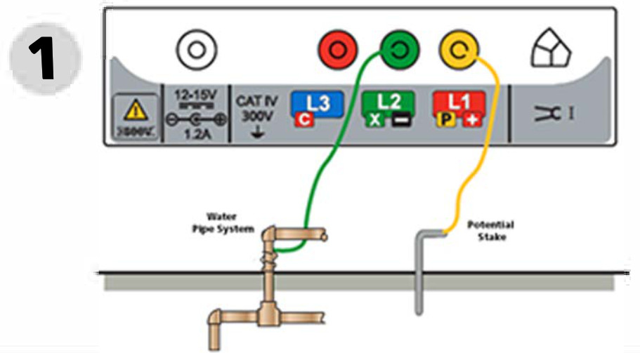


3 Press TEST and release
3-POLE
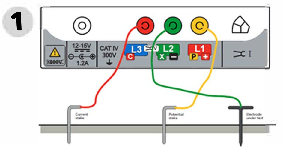


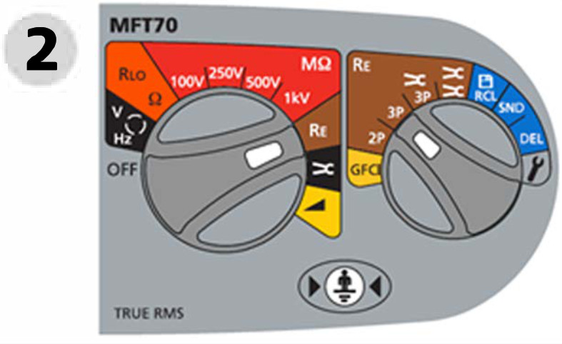

3 Press TEST and release
3-POLE


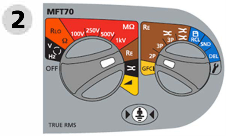


3 Press TEST and release
3-POLE
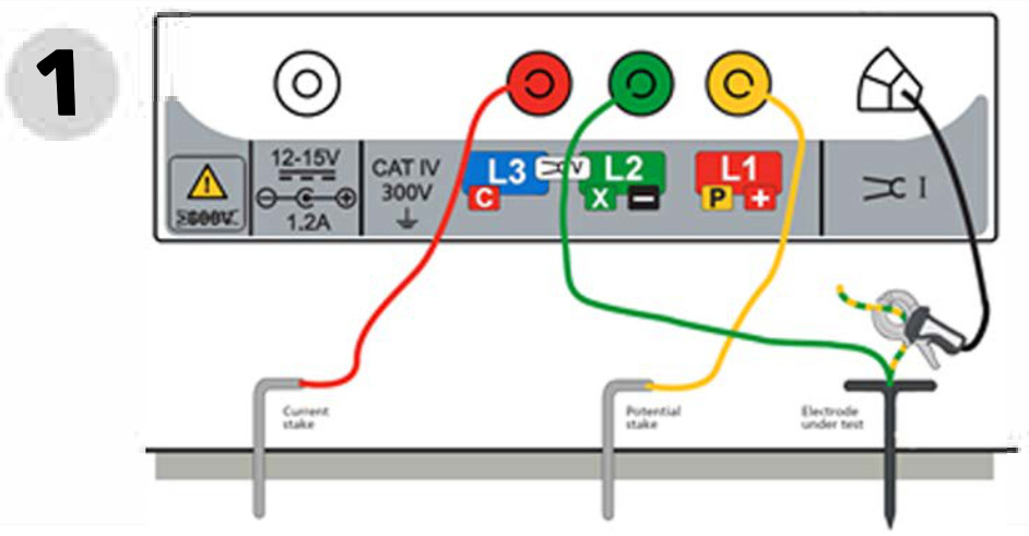


3 Press TEST and release
Ensure that the Megger Current Clamp jaw mating surfaces are free of dust and contamination!
3- POLE


Use this method if you’re working with concrete slabs or asphalt!
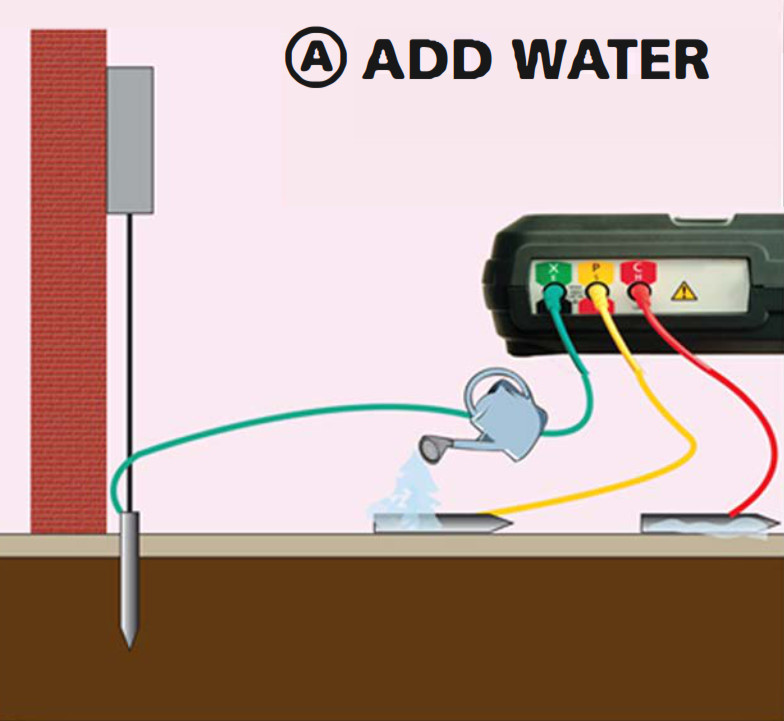

Simple lay the probes on their sides and spray with water to make the connection.
Test Equipment Depot – 800.517.8431 – 5 Commonwealth Ave, MA 01801 – TestEquipmentDepot.com
References
[xyz-ips snippet=”download-snippet”]

