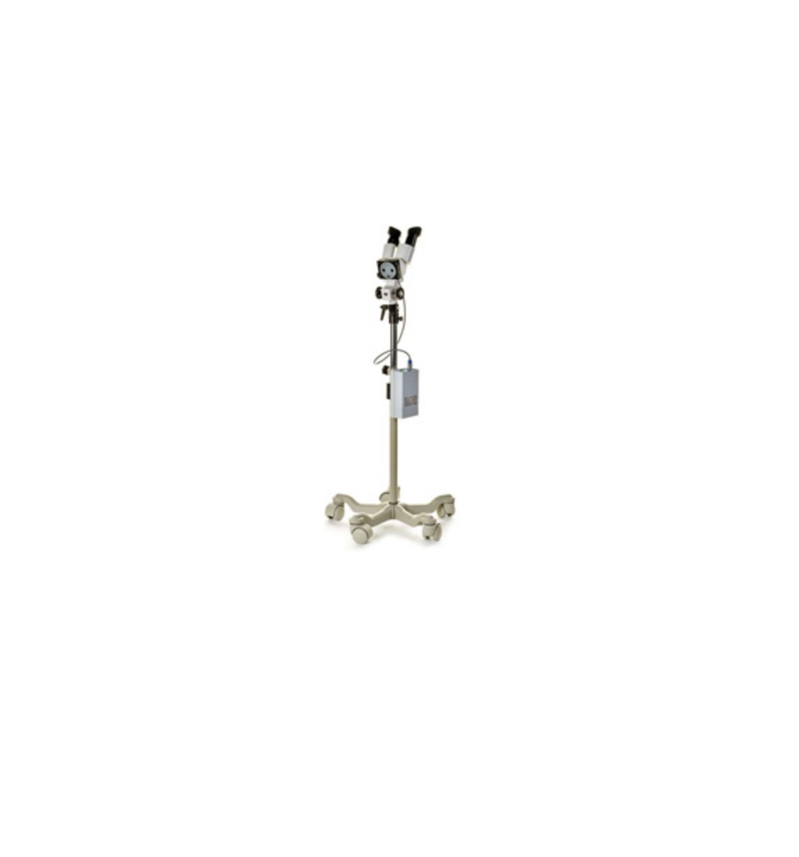
GIMA Observation Lamp
Introduction
Dear User, you are kindly invited to read this manual carefully before proceeding to use the Product in order to safeguard yourself and other people from any injuries. This appliance is a Class 1 medical device pursuant to European Directive on medical devices (MDD) 93/42/EEC (Annex IX) and 2007/47/EC. The manufacturer declares that this Product is in compliance with Annex I (Essential requirements) of Directive 93/42/EEC and certifies such conformity by affixing the CE marking. This User manual is valid for the following model: SOLESUD 2-LED.
The customer service is at your disposal in case of Product details, information concerning its use, identification of spare parts being required and for any other queries you might have concerning the appliance, for ordering spares and for matters relating to assistance and warranty. GIMA TECHNICAL ASSISTANCE OFFICE FOR CLIENTS Via Marconi, 1 20060 GESSATE (MI) ITALY Tel. +39 02 953854209 Fax +39 02 95381167http://www.gimaitaly.com e-mail: [email protected]
The contents of this manual may be amended by GIMA, without prior notice or any further obligations, in order to make changes and improvements. The reproduction and translation, including partial, of any part of this manual is forbidden without the written permission of GIMA. GIMA reserves the right to change, cancel or otherwise amend the data contained in this document at any time and for any reason without prior notice inasmuch as GIMA is constantly seeking new solutions which lead to product evolution. GIMA therefore reserves the right to make changes to the supplied Product in terms of shape, fittings, technology and performances. With regard to translations into languages other than Italian, reference shall always be made to the Italian edition of this User manual.
General information
The EM (Electro-Medical) DEVICE to which this manual refers is a LAMP for diagnosis or observation. For ease of description, in this manual this EM EQUIPMENT will be called “Product”. This manual is an integral part of the Product as indicated by European Directives 93/42/EEC and 2007/47/EC. Always keep this operator’s manual close to the lamp. GIMA disclaims all liability for any injuries to persons or damage to things caused by the installation, maintenance or use of the Product by unqualified operators. By qualified operator is meant whosoever has attended a course relating to the installation, maintenance and use of the product organised by GIMA or, alternatively, whosoever has carefully read this installation manual.GIMA does not authorize third parties to perform special maintenance jobs. Should a problem arise, contact GIMA. The end user is entirely responsible for Product installation activities; no costs or responsibilities relating to the installation and/or commissioning of the Product may therefore be traced back and/or in any case attributed to GIMA. The ceiling or wall masonry works for Products to be installed on ceilings or walls, and the electrical works for supplying power to the Product shall be carried out in a workmanlike manner by suitably qualified personnel to ensure these are sturdy and safe. By way of example only, the following professional figures are deemed as suitably qualified:
Construction Engineer, Draughtsman, Building firm duly registered in the professional Register (for the masonry works)
Electrical Engineer Electro-technical expert qualified to work as an electrician (for the electrical works) The Product is an EM electro-medical equipment and therefore falls within the field of application of the IEC 62353 standard. Consequently, any operation performed on the Product must be carried out in compliance with the IEC 62353 standard, where applicable.
Operator qualification:This paragraph describes the requirements and qualifications which the operators involved in the various stages of Product life and use must possess.
| Installation | Installer and/or qualified technician |
| Use | Professional medical personnel |
| Routine maintenance | Qualified technician with required technical-professional skills |
| Special maintenance | GIMA or authorized Dealer |
| Assistance | GIMA or authorized Dealer |
| Cleaning | Properly trained medical and paramedical personnel |
| Demolition | Comply with applicable laws on waste disposal. This product must not be disposed of in standard waste disposal bins. To avoid risks for the environment and health deriving from the dispersion of polluting substances in the environment, separate the various internal component parts such as iron, aluminium, plastic and electrical material, and dispose of these through authorized channels so as to ensure correct recycling. |
Packaging, transport, storage and characteristics of installation premises:Boxes containing the Product together with User manual. Transport is made by GIMA or any road-hauler as long as in compliance with the following characteristics: Temperature (°C): -15 / +60; Humidity: 10 / 75 %; Atmospheric pressure (hPa): 500 / 1060. The packaged Product must be stored (warehoused) in dry premises having the following characteristics: Temperature (°C): -15 / +60; Humidity: 10 / 75 %; Atmospheric pressure (hPa): 500 / 1060. The premises where the Product is started up must have the following characteristics: Temperature (°C): +10 / +40; Humidity: 30 / 75 %; Atmospheric pressure (hPa): 700 / 1060.
Graphic symbols used on the Product:Description of the symbols on plates, product and in manual:
 …………………….. …………………….. |
Graphic symbol showing product bears CE marking |  ………………… ………………… |
Manual reading obligation |
 |
Symbol indicating date of manufacture (month/year) |  |
Model |
 |
Manufacturer’s address |  |
Serial number |
 |
RECYCLING! The Product must be recycled separately | 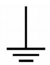 |
Functional earth |
 |
Stand-By | 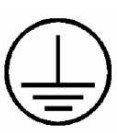 |
Protection earth |
 |
ON power |  |
OFF power |
 |
Top side of packaging |  |
Weight of packaging |
 |
Fragile packaging |  |
Protect from rain |
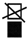 |
Do not stack packaging | 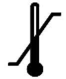 |
Limit temperature (indicate max limit at top right and min limit at bottom left) |
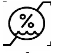 |
Humidity to be complied with (indicate max limit at top right and min limit at bottom left) | 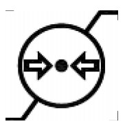 |
Pressure to be complied with (indicate max limit at top right and min limit at bottom left) |
 |
General warning signa |  |
General mandatory code of conduct signal |
Graphic symbol showing product bears CE marking Symbol indicating date of manufacture (month/year)
Manufacturer’s ![]() Declaration of Conformity:The company: RIMSA P. LONGONI S.r.l. Via Monterosa, 18/20/22 – 20831 SEREGNO (MB) ITALY declares under its own responsibility that the Product (Medical device for observation and diagnosis):
Declaration of Conformity:The company: RIMSA P. LONGONI S.r.l. Via Monterosa, 18/20/22 – 20831 SEREGNO (MB) ITALY declares under its own responsibility that the Product (Medical device for observation and diagnosis): made by RIMSA P.LONGONI S.r.l., complies with Annex VII of Directive 93/42/EEC dated 14/05/1993, enforced in Italy by Legislative Decree No. 46 dated 24 February 1997 and subsequent amendments (including Directive 2007/47/EC dated 05/09/2007, enforced in Italy by Legislative Decree No. 37 dated 25 January 2010) and with the following standards:
- IEC 60601-1Part 1: General requirements for basic safety and essential performance)
- IEC 60601-2-41(Part 1: Particular requirements for the safety of surgical luminaires and luminaires for diagnosis)
- IEC 60601-1-2(Part 2: General requirements for basic safety and essential performance Collateral Standard: Electromagnetic disturbances – Requirements and tests)
Classification with reference to article 9 and Annex IX of Directives 93/42/EEC and 2007/47/ECDURATION: ort term duration (Annex IX, Par.1 “Definitions”, art.1, subsection 1.1)DESCRIPTION: Non-invasive medical device (Annex IX, Par.1 “Definitions”, art.1, subsection 1.2) Active medical device (Annex IX, Par.1 “Definitions”, art.1, subsection 1.4)CLASS I:(Annex IX, Par.3 “Classification”, art.3, subsection 3.3, Rule 12) and (Annex IX Par.3 “Classification”, art.1, subsection 1.1 Rule 1)
- The conformity assessment is developed with reference to article 11 of Directive 93/42/EEC and 2007/47/EC.
- RIMSA Quality System complies with UNI EN ISO 9001 and UNI CEI EN ISO 13485 standards and is certified by CSQ (CSQ certificate no. 9120.RMS1 and 9124.RMS2)
- The Medical Device to locally light up the patient’s body is marketed in NON STERILE form.
Warranty Certificate:
- The Product is covered by an 18-month warranty, including electrical parts
- The warranty begins on the date of product shipment from the GIMA warehouse to the buyer.
- In case of disputes, the date indicated on the “transport document” attached to the goods shall be deemed valid.
- The warranty only covers the sending of Product spare parts to the buyer or, in the event of GIMA considering the replacement of spare parts not feasible, the replacement of the entire product, after fabrication faults have been properly ascertained at the undisputable judgement of GIMA. The warranty does not therefore cover any other costs or expenses (including, by way of example but without limitation, labour costs, packaging costs and transport costs, etc.).
- The guarantee does not include the components subject to normal wear, such as halogen bulbs, LEDs, fuses, relays, ball bearings, etc.)
- The warranty does not cover:
- malfunctions due to failure to comply with user manuals;
- malfunctions due to installation and/or maintenance errors;
- malfunctions or faults caused by carelessness, negligence, incorrect use or other causes not attributable to GIMA;
- malfunctions or faults due to the fact that the electrical system of the premises where the device is installed is not in compliance with CEI 64-8 standards (standards for electrical systems in premises used for medical purposes) and similar standards.
- GIMA shall repay direct damages suffered by the buyer and which are documented as attributable to its product, caused within the warranty period, for an amount not above 40% of the net value of the product as indicated on the buyer’s invoice. GIMA’s liability is expressly ruled out for indirect damages or consequential damages (including cases of the lamp not being used) deriving from the supply.
- This warranty certificate replaces legal warranties for faults and non-conformities and rules out any other possible liability of GIMA originating from the supplied products.
- The payment of any damages to persons or things due to product malfunction or faults shall be limited to the maximum amount of GIMA’s insurance coverage for civil liability.
- The warranty shall be automatically invalidated in the event of:
- the Product having been tampered with or modified by the buyer or third parties;
- – the Product having been repaired by the buyer or third parties, without following the instructions in user manuals;
- the Product serial number having been cancelled, defaced or removed;
- the buyer not being up to date with payments.
- For jobs to be done under warranty, the buyer shall contact GIMA only.
- The component parts replaced under warranty must only be returned to GIMA, if so requested by GIMA, carriage free and suitably packed.
- In case of failure to return a part requested by GIMA, the cost of the component part will be charged.
- GIMA cannot accept returns from end users or in any case from parties other than the buyer.
- Products returned to GIMA must be complete with documentation authorising such return and another document describing the malfunction.
- For everything not indicated on this warranty certificate, reference shall be made to the laws of Italy.
- For all disputes deriving from or related to the orders to which this warranty certificate applies and which cannot be amicably settled between the parties, the only competent law court shall be that of Milan.
Importance of personal safety
Intended useThe Product has been designed to light up the area of the patient undergoing observation and diagnosis and is intended for use in doctors’ surgeries. The Product correctly lights up the operating field from a minimum distance of 40 cm and a maximum distance of about 70 cm, from the point of light emission. The Product, in conformity with the IEC 60601-2-41 standard, is defined as a lamp for diagnostics:
- a lamp for diagnostics is a lamp used to locally light up the body of a patient, in order to makediagnosis or treatment easier. These can be interrupted without any danger for the patient in case of the light going off. (The Product is not intended for use in operating theatres).
Environmental conditions
- The Product is not suitable for use in explosion-risk areas.
- The Product is not suitable for use wherever there are flammable mixes of anaesthetics with air, oxygen or N2O (laughing gas).
- The Product is not suitable for use in environments rich in oxygen and use is not intended in the presence of flammable agents.
- During operation, the ambient temperature must be between 10°C and 40°C.
- Relative humidity must be between 30% and 75%.
- Atmospheric pressure must be between 700 and 1060hPa.
Safety conditions (secondary effects)
- Do not direct the light source into the patient’s and/or operator’s eyes.
- Obligation to adequately protect the patient’s eyes.Failure to follow such precautions could cause glare and potential damage to the retina.
- Never place and/or hang anything on the Product.Unless this precaution is taken, positioning will not be reliable and the danger exists of such objects falling in the operating area.
- Never hang on the Product with the body weight of a person. Failure to follow such precaution could damage the Product structure. –
- Never cover the head of the Product during operation. Failure to comply could prevent heat exchange with the environment and the Product could overheat.
- Avoid knocking the rocker arms and Product head.
- A violent knock could damage the Product and pieces of paint could chip off and fall onto the operating field in the patient area. – To avoid any significant risk of reciprocal interference due to the presence of the Product during specific exams or treatments, see section 9 of the manual.
Controls to be performed every time before the lamp is usedTo make sure the Product is safe and provides a correct diagnosis, every time before use, the operator must check: –
- The lamp has been correctly disinfected;
- The emitted light is stable and of adequate intensity;
- The flexible arm remains in the selected position, without falling.
Product installation
 Before proceeding to install the Product, first of all check the presence of all the packaging and that this is in good condition and has not been damaged during transport. Claims will only be taken into consideration if the seller or carrier has been immediately notified. All claims must be made in writing. Goods always travel under the responsibility and at the risk of the buyer. Keep the original packaging in case the Product has to be re-dispatched.The product is supplied with different support systems, to be selected as required:
- `S/11′ wing-nut vice for fastening to table;
- `S/12 MED’ wall-fastening clamp;
- `Z400072′ rail bar clamp, `Z400075′ rail bar supplied with 1 metre bar length, 3 spacers, 3 wallanchors and 3 screws for fastening the anchors to the bar;
- `RL’ floor lamp consisting of upright and 5 wheels with pedal-operated lock system.
![]() To avoid the risk of electric shocks, this appliance must only be connected to mains supplies with earth connection.
To avoid the risk of electric shocks, this appliance must only be connected to mains supplies with earth connection.
Installation of wall version (S/12 MED fastening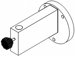
- Fasten the clamp S/12 MED to the wall with 3 expansion screws. GIMA does not supply screws.
- The wall must be a supporting wall and be made of solid brick. Installation on walls of perforated bricks and plasterboard is only allowed with the fitting of a plate on the opposite side of the wall (sandwich closing). GIMA suggests using M5 screws.
- Fit the lamp in the hole located in the upper part of the clamp S/12 MED. · Screw up the threaded knob, making sure this fit into the mill hole of the lamp pin in such a way as to prevent it accidentally coming out.
- Insert the pin situated in the end of the power cable in the power socket.
Installation of wall version (bar rail fastening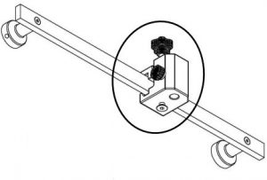

- Fasten the bar rail according to attached instructions MO002i.
- Fit the clamp on the bar and tighten the lower knob.
- Fit the lamp in the hole located on the clamp.
- Screw up the threaded knob, making sure this fit into the mill hole of the lamp pin in such a way as to prevent it accidentally coming out. · Insert the pin situated in the end of the power cable in the power socket.
Installation of 5-spoke floor version (RL)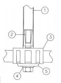

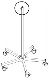
- To fit the stand keep the iron rod (1) in vertical position with side up of the lamp so the internal conical nut goes down (2).
- Put the iron steel on the mobile (3) and screw down bolt (4) with washer and plate (5) pulling down while screwing.
- Then fit the lamp in the hole located in the top part of the stand rod.
- Screw up the threaded knob, making sure this fits into the mill hole of the lamp pin in such a way as to prevent it accidentally coming out. ·
- Insert the pin situated in the end of the power cable in the power socket.
![]() In the floor version, operate all 5 wheel brakes during operation to ensure stability.
In the floor version, operate all 5 wheel brakes during operation to ensure stability.
First switch-onAt this point, the Product can be switched on to make sure it works properly.
-
- Press the green switch on the base;
- Make sure all LEDs and functions are working properly.
Check the result of Product installation and testing before useThe following instructions are to be deemed mandatory during the installation inspection phase, as they prove that all the various jobs referred to have been correctly done. Hence each single step must be ticked.
-
-
- Make sure the wall is suitable for Product installation.
- Make sure the stand pin has been correctly fitted in its fastening point.
- Make sure movement mechanisms are working properly. Check mechanical operation by means of direction and rotation movements.
- After switch-on, the Product must emit light from the reflector.
-
Description and operation
![]() Do not position the device so it is hard to reach and remove the power plug in case of an emergency.
Do not position the device so it is hard to reach and remove the power plug in case of an emergency.
The Product locally lights up the patient’s body thanks to 3 LEDs focalized by means of specific lenses. Positioning is easy thanks to the articulated arm and is done manually.The Product does not have a keyboard to operate. To switch on the Product, press the `I’ (ON) green light switch on the Product base. The intensity of the light cannot be adjusted. It can only be directed at the desired point thanks to the flexible arm, gripping it from the reflector. After use, press the `O’ (OFF) switch. To disconnect from the mains, remove the plug.
Cleaning and disinfecting
Cleaning the Product
![]() Before going ahead with cleaning operations switch off the Product by detaching the plug, make sure it cannot be switched back on and leave it to cool down. Only clean the Product when it is cold.Protect the Product from water spray and detergents and do not clean it with liquids. Clean with suitable detergents with low alkaline content and chlorine free. Do not use abrasive products, petrol, paint thinners, alkaline detergents, acids, containing alcohol or aldehydes; dose the cleaning agents so no liquids penetrate inside the lamp elements and into the support arm system. Clean the Product with a damp, but not wet, cloth.
Before going ahead with cleaning operations switch off the Product by detaching the plug, make sure it cannot be switched back on and leave it to cool down. Only clean the Product when it is cold.Protect the Product from water spray and detergents and do not clean it with liquids. Clean with suitable detergents with low alkaline content and chlorine free. Do not use abrasive products, petrol, paint thinners, alkaline detergents, acids, containing alcohol or aldehydes; dose the cleaning agents so no liquids penetrate inside the lamp elements and into the support arm system. Clean the Product with a damp, but not wet, cloth.


Disinfecting![]()
![]()
![]()
Protect the Product from water spray and detergents and do not clean it with liquids. Disinfectants can contain substances which are harmful for the health – only use disinfectants in accordance with the rules on hygiene established by the hospital; the Product operator must comply with the rules established by the national commission for hygiene and disinfection. To prevent damaging parts in stainless steel or aluminium, only use disinfectants which are chlorine and halogen free; to prevent the plastic parts becoming fragile, use only disinfectants with low alcohol content; dose the disinfectants so no liquids penetrate inside the lamp elements and into the support arm system. Clean the Product with a damp, but not wet, cloth.The Product is best disinfected every time before use. To clean the lamp, the support need not be removed.
![]()
![]()
Adjustments
Yearly inspections by operatorKeep to the yearly inspection schedules and inspect the product according to IEC 62353 standard.
Repairs

AdjustmentsThe Product is sold balanced and does not require further adjustment. In the event of the Product becoming stiff or loose over time, contact GIMA customer service.
Troubleshooting
| No. | Problem` | Solution |
| 1 | The Product fails to work | Contact the after-sales service |
| 2 | The Product does not remain in position | Contact the after-sales service |
| 3 | The light flickers | Contact the after-sales service |
| 4 | The light beam is not focalized | Contact the after-sales service |
Routine maintenance
| No | Internal | Action |
| 1 | Once a year | Perform complete movements of Product arm and make sure movement is smooth. If the Product fails to maintain its position or its movements are hard, contact the after-sales service. |
| 2 | Once a year | Make sure the retention screws of connections are tightened properly. If these are not properly fastened, adequately tighten. |
| 3 | Once a year | Check the condition of the Product paint. Make sure there are no paint pieces that could fall in the patient area. If any paint pieces deemed hazardous are found, contact the after-sales service. |
Technical properties
| Technical properties | SOLESUD 2-LED |
| Illumination Ec at 50cm distance ± 10% [Lux | 60,000 |
| Colour temperature (±5%) [K] | 4,000 |
| Colour rendering index Ra [-] | 94 |
| Max irradiance [W/m2 | 214 |
| Max radiation in UV [W/m2 ] | 0.016 |
| Power connection details | |
| Primary alternate voltage [V ac] | 100-240 |
| Frequency [Hz] | 50/60 |
| Light source | N°3 LED |
| Duration of LED diode light source [hr] (this figure can vary according to power peaks and operating frequency) | 60,000 |
| General data | |
| Colour | RAL 9003 |
| Directive | 93/42/EEC (incl. 2007/47/EC) |
| Standards | EN 60601-1 and EN 60601-2-41 |
| Classification of Medical Device | Class I |
| Essential performance | Distribution of minimum and adequate lighting (luminous flux emitted by the ME equipment does not vary by more than 20% during use and the colour temperature and the colour rendering index are stable and are within the range 3000K-6700K and 85-100, respectively). |
| Limitation of energy in the operating field (UV-irradiance for wavelengths below 400 nm does not exceed 10 W/m2 and the total irradiance Ee in the lighted area does not exceed 1000 W/m2 at a distance of 500 mm). | |
| IP Classification | IP20 |
| Operating conditions | Continuous operation |
| Mains power voltage insulation means | Integrated power plug |
| Fuses incorporated | T1AH 250V, 5×20 |
| Dimensions | |
| Diameter of lamp body [cm] | 9 |
| Lens diameter [cm] | 3.2 |
| Light emission surface [cm2 ] | 22 |
| Overall dimensions [cm] | 100x35x15 |
| Lamp weight [kg] | 3 |
| Markings | |
| In conformity with Directive 93/42/EEC (and 2007/47/EC) | |
| All technical light measurements are to be deemed with a tolerance of ±6% for metrological and manufacturing reasons |
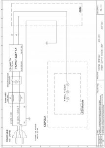
Wiring diagram

EMC Declaration
The Product has been tested according to EN60601-1-2 standard to ensure correct electromagneticcompatibility. Portable and mobile RF-communications equipment can affect the Product. The Product should notbe used adjacent with other equipment and that if adjacent use is necessary the Product should beobserved to verify normal operation. The Product is intended for use in the electromagnetic environment specified below. The customer or the user of the Product should assure that is used in such an environment.
|
Immunity test |
Conformity |
Electromagnetic environment – directives |
|
RF Emissions CISPR 11 |
Group 1 |
The Product uses RF energy only for its internal function. Therefore, its RF emissions are very low and are not likely to cause any interference in nearby electronic equipment. |
|
RF Emissions CISPR 11 |
Class A |
The Product is suitable for use in all establishments other than domestic, and may be used in domestic establishments and those directly connected to the public low-voltage power supply network that supplies buildings used for domestic purposes, provided the following warning is heeded:
WARNING: This equipment/system is intended for use by healthcare professionals only. This equipment/system may cause radio interference or may disrupt the operation of nearby equipment. It may be necessary to take mitigation measures, such as reorienting or relocating the Product or shielding the location. |
|
Harmonic emissions IEC 61000-3-2 |
Class A |
|
|
Voltage fluctuations /flicker emissions IEC 61000-3-3 |
Conforming |
|
| NOTE: The EMISSIONS characteristics of this equipment make it suitable for use in industrial areas and hospitals (CISPR 11 class A). If it is used in a residential environment (for which CISPR 11 class B is normally required) this equipment might not offer adequate protection to radio-frequency communication services. The user might need to take mitigation measures, such as relocating or re-orienting the equipment. |
| Immunity test | Test level to IEC 60601-1-2 | 2 Conformity level | Electromagnetic environment – directives |
| Electrostatic discharge (ESD) IEC 61000-4-2 | +/- 8 kV contact +/- 15 kV ai | +/- 8 kV contact +/- 15 kV air | Floors should be wood, concrete or ceramic tile. If floors are covered with synthetic material, the relative humidity should be at least 30% |
| Electrical fast transient / burst IEC 61000-4-4 | +/- 2 kV for power supply unit +/- 1 kV for input/output lines | +/- 2 kV for power supply lines +/- 1 kV for input/output lines | Mains power quality should be that of a typical commercial or residential environment. |
| Surge IEC 61000-4-5 | +/- 1 kV differential mode +/- 2 kV common mode | +/- 1 kV differential mode +/- 2 kV common mode | Mains power quality should be that of a typical commercial or hospital environment. |
| Voltage dips, short interruptions and voltage variations on power supply input lines IEC 61000-4-11 | 95% dip in UT) For 0,5 cycle 40% of UT (60% dip in UT) For 5 cycles 70% of UT (30% dip in UT) For 25 cycles <5% UT (>95% dip in UT) For 5 sec | 95% dip in UT) For 0,5 cycle 40% of UT (60% dip in UT) For 5 cycles 70% of UT (30% dip in UT) For 25 cycles <5% UT (>95% dip in UT) For 5 sec | Mains power quality should be that of a typical commercial or hospital environment. If the user of the Product requires continued operation during power mains interruptions, it is recommended that the Product be powered from an uninterruptible power supply or battery |
| Power frequency (50/60Hz) magnetic field IEC 61000-4-8 | 30 A/m | 30 A/m | Power frequency magnetic fields should be at levels characteristic of a typical location in a typical commercial or hospital environment. |
| NOTE: | UT is is the a.c mains voltage prior to application of the test level | ||
| Conducted RF IEC 61000-4-6 Radiated RF IEC 61000-4-3 | 3 Veff 150 kHz to 80 MHz 3 V/m 80 MHz to 2.5GHz | 3 Veff 3 V/m | Portable and mobile RF communications equipment should be used no closer to any part of the Product, included cables, than the recommended separation distance calculated from the equation applicable to the frequency of the transmitter. Recommended separation distance d = 1.2√P 150 KHz to 80 MHz d = 1.2√P 80 MHz to 800 MHz d = 2.3√P 80 MHz to 2.5 GHz where P is the maximum output power rating of the transmitter in watts (W) according to the transmitter manufacture and d is the recommended separation distance in meters (m). Field strengths from fixed transmitters, as determined by an electromagnetic site survey, should be less than the compliance leave in each frequency range. Interference may occur in the vicinity of equipment marked with the following symbol.
|
| NOTE 1: At 80 MHz and 800 MHz, the higher frequency range applies. NOTE 2: These guidelines may not apply in all situations. Electromagnetic propagation is affected by absorption and reflection from structures, objects and people. |
| Recommended separation distance between portable and mobile RF communications equipment and the Product | |||
| The Product is intended for use in an electromagnetic environment in which radiated RF disturbances are controlled. The customer or the user of the Product can help prevent electromagnetic interference by maintaining a minimum distance between portable and mobile RF communications equipment (transmitters) and the Product as recommended below, according to the maximum output power of the communications equipment. | |||
| Rated maximum output power of transmitter W | Separation distance according to frequency of transmitter m
|
||
| 150 kHz to 80 MHz d = 1.2√P | 80 MHz to 800 MHz d = 1.2√P | 800 MHz to 2.5 GHz d = 2.3√P | |
| 0.01 | 0.12 | 0.12 | 0.24 |
| 0.1 | 0.38 | 0.38 | 0.73 |
| 1 | 1.2 | 1.2 | 2.3 |
| 10 | 3.8 | 3.8 | 7.3 |
| 100 | 12 | 12 | 23 |
| For transmitters rated at a maximum output power not listed above, the recommended separation distance d in meters (m) can be estimated using the equation applicable to the frequency of the transmitter, where P is the maximum output power rating of the transmitter in watts (W) according to the transmitter manufacturer. NOTE 1: At 80 MHz and 800 MHz, the separation distance for the higher frequency range applies. NOTE 2: These guidelines may not apply in all situations. Electromagnetic propagation is affected by absorption and reflection from structures, objects and people. |
References
[xyz-ips snippet=”download-snippet”]

