ULINE Washdown Platform Scale

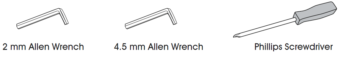
TOOLS NEEDED
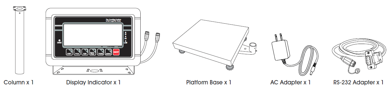
PARTS
SETUP
WARNING! Disconnect all power to the scale before installing, cleaning or servicing. Failure to do so could result in bodily harm or damage to the scale.
SELECTING THE LOCATION
The scale should always be used in an environment that is free from excessive air currents, corrosives, vibration and temperature or humidity extremes. These factors will affect displayed weight readings.Avoid placing the scale next to or near:
- Open windows or doors.
- Air conditioning or heat vents.
- Vibrating, rotating or reciprocating equipment.
- Magnetic fields.
- Equipment that generates magnetic fields.
- Direct sunlight.
- An unstable work surface.
- A dusty environment.
- Large users of electricity, like welding equipment or large motors.
- Unstable power sources.
UNPACKING THE SCALE
- Remove the scale parts from packaging.
- Place the scale on a flat surface.
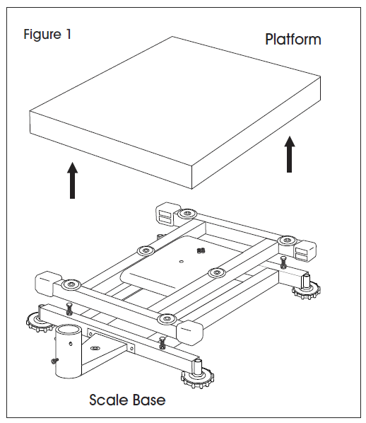
- Remove the platform from top of the scale base.(See Figure 1)
- Remove the styrofoam pad from under the platform.
REMOVING THE SHIPPING SCREW
Remove shipping screw from bottom of the scale base using a 2 mm Allen wrench. (See Figure 2)
INSTALLING THE PLATFORM
- Remove protective covering from the scale platform.
- Place the platform on top of the scale base.
CAUTION! Do not press down with excessive force. This could damage the load cell.
LEVELING
- The scale is equipped with a level indicator located on the back of the scale on the base bracket.
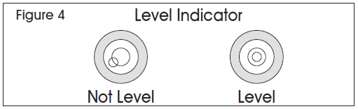
- Use the adjustable leveling feet located on the bottom of the scale until the bubble appears in the center of the indicator. (See Figure 4)
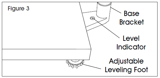
NOTE: Check the level indicator every time scale is moved to a new location to verify scale is balanced.
ASSEMBLING THE COLUMN
- Unscrew the carriage bolt in the column using a Phillips screwdriver and detach the support bracket from the column. Unscrew four small Phillips head bolts from the support bracket. Set column, support bracket, carriage bolt and small Phillips head bolts aside.
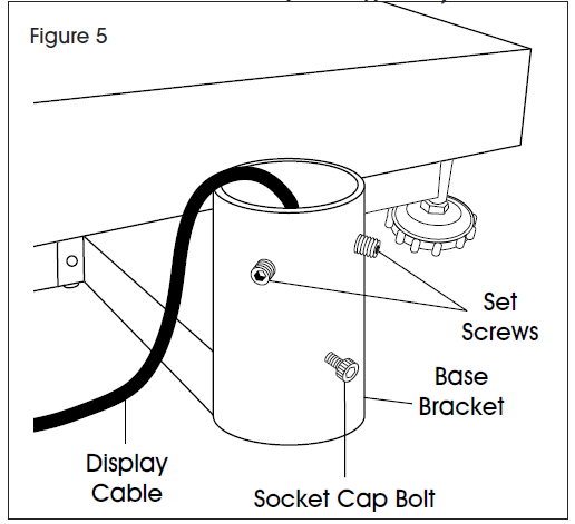
- On the base bracket, loosen two set screws using a 2 mm Allen wrench and the socket cap bolt using a 4.5 mm Allen wrench. (See Figure 5)
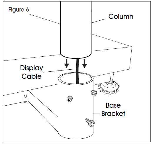
- Insert column into base bracket. Make sure column rests on the bottom of the base bracket. (See Figure 6) Pull display cable all the way through the column so no slack is under the platform.
- Secure column with set screws using a 2 mm Allen wrench and with the socket cap bolt using a 4.5 mm Allen wrench, but do not tighten.
ATTACHING INDICATOR TO THE COLUMN
- Place the indicator bracket onto the top (flat side) of the support bracket. Align the large center holes and four small holes.
- Insert four small Phillips head bolts through the small holes on top of the indicator bracket and the support bracket. Tighten until pieces are securely attached.
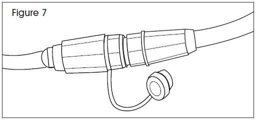
- Feed black display cable from the display indicator through the large center holes in the indicator bracket and support bracket. Connect to the display cable end at the top of the column by aligning holes and pushing connectors together. Twist a quarter of a turn to lock into place. (See Figure 7)
- Place support bracket into the column with the display facing the platform. Pull display cable all the way through the column so excess is under the base bracket. Make sure RS-232 cable is on the back of the display. (See Figure 8)
- Tilt display to desired position.
- Insert carriage bolt back into the column and tighten.
- Tighten base bracket set screws and socket cap bolt.

CONNECTING POWER
The scale can operate continuously by connecting the AC adapter to an outlet or operate eight hours on a fully charged battery.
WARNING! Only use the original AC adapter and battery that came with the scale. Using an alternative AC adapter or battery could damage the scale.
AC ADAPTERPlug the AC adapter into the AC adapter socket on the back of the indicator. Plug the AC adapter plug into a standard 110 volt outlet.
WARNING! When AC adapter is not in use, AC adapter socket must be capped. Leaving the socket uncapped during water exposure could result in damage.NOTE: Verify the local voltage and receptacle type are correct for the scale.
BATTERYThe scale is equipped with a rechargeable battery.When the battery voltage is low, a battery symbol will appear in the lower left-hand corner of the display. After 15 minutes, the backlight will start to flicker and the display will show Bat lo. The scale will automatically turn off 30 minutes after the symbol appears.
CHARGING THE BATTERYWhen the battery indicator ( ) appears in the lower left-hand corner of the display, the battery needs to be recharged.Plug the AC adapter into a power source to charge the battery. Scale does not need to be turned on. It will take 12 hours to fully charge the battery.The charging indicator is located on the left side of the display, above the word CHARGE. The indicator light color will change to indicate the battery status:
- RED – Battery needs to be recharged.
- ORANGE – Battery is being charged.
- GREEN – Battery is fully charged.
BATTERY MAINTENANCERecharge battery every three months when not in use.If the scale is not used for an extended period of time, remove the battery from the battery compartment to avoid leakage. Store the battery in a sealed bag or box in a dry, temperate environment.
DISPLAY AND KEYPAD
DISPLAY AND KEYPAD DEFINITIONS
| # | NAME | DESCRIPTION |
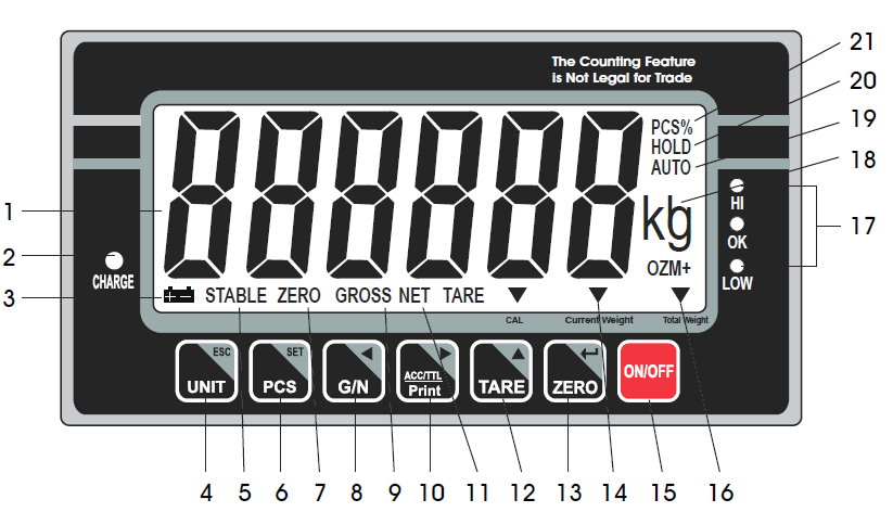
| 1 | DISPLAY | Displays the total weight, unit weight and number of counted items. |
| 2 | CHARGE | Charging indicator. Indicates the battery charging status. |
|
3 |
|
Battery indicator. Indicates battery is low and needs to be recharged. |
|
4 |
UNIT ESC | Units key. Used to change weighing unit. ESC key. Used to exit the set-up menu. |
| 5 | STABLE | Stable indicator. Indicates the scale weight is stable. |
|
6 |
PCS SET | Count key. Used to enter the counting operation. Setup menu key. Used to enter setup menu. |
| 7 | ZERO | Zero indicator. Indicates the scale is at zero. |
|
8 |
G / N
t |
Gross/Net Weight key. Used to show the net or gross weight.
Left arrow key. Used to move the active digit to the left. |
| 9 | GROSS | Gross indicator. Indicates scale is displaying the gross weight. |
|
10 |
ACC / TTL Print
u |
Accumulation key. Used to enter and show accumulated weights or counts in memory.
Print key. Used to send data to a printer or PC.
Right arrow key. Used to move the active digit to the right. |
| # | NAME | DESCRIPTION |
| 11 | NET | Net indicator. Indicates scale is displaying the net weight. |
|
12 |
TARE
p |
Tare key. Used to zero out the weight of a container being used to hold small parts.
Value increment key. Used to change the active digit value. |
|
13 |
ZERO
|
Zero key. Used to clear and zero the display.
Enter key. Used to enter the selected menu, sub-menu and setting. |
| 14 | CURRENT WEIGHT | Current weight indicator. Indicates current weight in accumulation mode. |
| 15 | ON / OFF | On/off key. Used to turn the scale on or off. |
| 16 | TOTAL WEIGHT | Total weight indicator. Indicates total weight in accumulation mode. |
| 17 | HI / OK / LOW | Limits indicator. Indicates the high-low limits in weighing and counting. |
| 18 | LB / OZ / KG | Weighing unit indicator. Indicates current weighing unit. |
| 19 | AUTO | Automatic accumulation indicator. Indicates the scale is in automatic accumulation mode. |
| 20 | HOLD | Hold indicator. Indicates the scale is in dynamic weighing mode. |
| 21 | PCS% | Counting mode indicator. Indicates scale is in counting mode. |
OPERATION
PRIOR TO USE
- Fully charge the battery before using scale for the first time.
- Let the scale warm up for 15 minutes before use.
WARNING! Never drop items onto the platform. The scale is a sensitive precision instrument.WARNING! Do not exceed the scale capacity and overload the scale.WARNING! Do not stack items on the scale platform when the scale is not in use.
TURNING THE SCALE ON/OFF
ON/OFF key is located in the lower right hand corner of the display.
CAUTION! Never power the scale on with weight on the platform.
- To turn the scale on, press the ON/OFF key . The scale will show the version and enter a self-test mode. After completing the self-test, the scale will enter the weighing application mode.
- To turn the scale off, press the ON/OFF key
CALIBRATION
The scale is pre-calibrated during production. You must use a precision test weight to properly calibrate the scale. The test weight CANNOT exceed the scale’s capacity.
NOTE: Calibration can be done in English (lb.) and Metric system weight (kg) at the scale’s full capacity.
CALIBRATION WEIGHTS
| Model # | Lb. | Kg |
| H-5836 | 100 lb. | 50 kg |
| H-5837 | 200 lb. | 100 kg |
ZERO
If there is a minor weight displayed without anything on the platform, press the ZERO key to clear the display. Zero indicator will be shown on the display.
TAREWhen weighing an item that is in a container, taring stores the container weight to memory so only the item weight is displayed.To store tare weight into memory and set display to zero:
- Place an empty container on the platform.
- Press the TARE key. The net indicator will be displayed on the bottom of the display.
- The container’s weight is then stored in the scale’s memory and zero is displayed.
- Add pieces to the container. As the pieces are added, their net weight will be displayed.
- Press the G/N key to display the gross weight and net weight.
- Removing the container from the platform will cause the scale to display the container’s negative weight. Pressing the TARE key will readjust the scale to zero.
AUTOMATIC ACCUMULATION
Use this application to automatically add weighing and counting values to the scale memory and to print values if a printer is connected.NOTE: Automatic accumulation must be enabled. See Setup section on page 10.When in the automatic accumulation application, the auto indicator will be shown in the upper right hand corner of the display.
- Place items to be weighed or counted on the scale platform.
- Once the stable indicator is shown on the display, the scale will make a beeping sound.
- ACC 1 will be shown on the display and the total value will be displayed for three seconds. Weighing or counting value will be stored into memory.
- Remove items from platform. Display will return to zero or a negative value.
- Add additional items to platform. New data will be added to memory. Continue until all data is added.
- To recall data and clear data, see sections above.
DYNAMIC WEIGHING
Use this mode to weigh moving items.
- Press and release the TARE key and the ZERO key at the same time to enter the dynamic weighing mode. The hold indicator will appear in the upper right hand corner of the display.
- Place item to be weighed on the scale platform. Once the stable indicator appears, the final weight will be shown on the display.
- Press and release the TARE key and the ZERO key at the same time to exit the dynamic weighing mode.
RS-232
To use the RS-232 port, connect the gray RS-232 adapter to the gray RS-232 cable on the display indicator. (See Figure 9)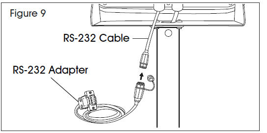
SPECIFICATIONS
RS-232 output of weighing data:
- Code: ASCII
- Data Bits: 8 data bits
- Parity: No Parity
- Baud Rate: 600bps – 900bps selectable.
RS-232 (9-PIN D TYPE CONNECTOR)
| Pin 2 | RXD | Input | Receiving Data |
| Pin 3 | TXD | Output | Transmission Data |
| Pin 5 | GND | — | Signal Ground |
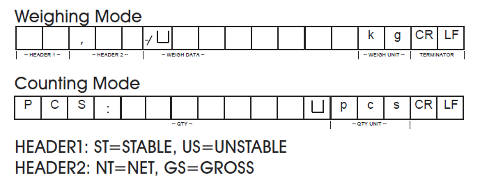
CONTINUOUSLY OUTPUT PROTOCOL
Con2:

Header0=02HHeader1 follow decimal pointDecimal point=0, header1=22HDecimal point=1, header1=23HDecimal point=2, header1=24HDecimal point=3, header1=25HDecimal point=4, header1=26HHeader2 follow weigh status, default value=20HIf in net mode (tare value not 0), header2=header2|01HIf gross weight “-“, header2=header2|02HIf overload or gross weight “-“, header2=header2|04HIf unstable, header2=header2|08HIf weighing unit=kg, header2=header2|10HHeader3 follow weighing unitIf weighing unit=g, header3=21HIf weighing unit=oz, header3=23HWeight1~weight6: weighing dataTare1~tare6: tare valueTerminator1: 0DHTerminator2: 0AH
Con3:

HEADER0=01HHeader1 follow weight “+” or “-”When weight “+”, header1=”+”, when weight “-“, header=”-”Weight1~weight7: weight data (include decimal point)Unit1~unit2: weight unitStatus: when stable, status=0, when unstable, status=1Terminator1: 0DHTerminator2: 0AH
LEGAL FOR TRADE
When the indicator is used in trade or a legally controlled application, it must be set up, verified and sealed in accordance with local weights and measures regulations. It is the responsibility of the purchaser to ensure that all pertinent legal requirements are met.
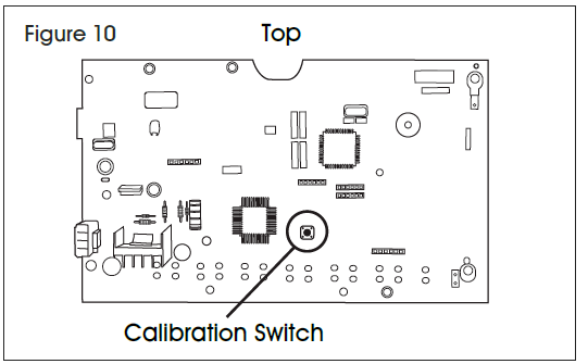
CALIBRATION
- Break the seal on the indicator housing.
- Open the housing.
- See calibration process on page 5. Complete steps 1-5.
- After step 5, press the calibration switch on the mainboard. (See Figure 10)
- Complete remaining calibration steps on page 5.
VERIFICATIONThe local weights and measures official or authorized service agent must perform the verification procedure.
SEALINGThe local weights and measures official or authorized service agent must apply a security seal to prevent tampering with the settings.
AUTO POWER-OFFWhen the auto power-off time is enabled, the scale will automatically turn off when there has been no load on the platform and the scale is stable at zero position for a specified period of time (in minutes). At startup, the auto power-off is disabled. Enter this menu to turn the auto power-off feature on or off.
HIGH/LOW LIMIT BEEPING SOUNDAt startup, the beeping sounds are set to beep when weights are inside the limits. Enter this menu to change the beeping sound setting.
BAUD RATEBaud rate is the RS-232 transmission speed. If using a printer, both the printer and the scale must be set to the same baud rate. At startup, the baud rate is set at 9,600. Enter this menu to change the baud rate setting
MAINTENANCE
CLEANING: CAUTION! Disconnect the unit from the AC adapter and cap AC adapter socket before cleaning. Do not use with pressure washers or other high pressure water jets. Rated IP65 for use with hoses.
Use a mild detergent for the display and keypad.WARNING! Do not use solvents, chemicals, alcohol, ammonia or abrasives.Use a stainless steel cleaning solution for the stainless steel indicator housing and platform.Apply cleaner to a clean, damp cloth and wipe surface. Dry thoroughly.
TROUBLESHOOTING
| ERROR | OPERATING ISSUE | RECOMMENDATIONS |
| Inaccurate weights | Shipping screw needs to be removed.
Scale needs to be recalibrated. |
Remove shipping screw.
Recalibrate the scale. |
| Err 4 | Scale needs to be recalibrated. | Recalibrate the scale. |
| Err 6 | Load cell connectivity issue.
AD board connectivity issue. |
Verify all load cell connection wires are secure.
Verify all AD board connection wires are secure. |
| -OL- | Maximum capacity exceeded. | Remove load from platform. |
| Bat lo | Battery needs to be recharged. | Recharge battery. |
If the problem persists or the troubleshooting section does not resolve or describe your problem, contact Uline Customer Service at 1-800-295-5510.

[xyz-ips snippet=”download-snippet”]