![]()
Installation Instructions for theHeavy Duty Pressure TransducersMLH Series, 6 bar to 550 bar | 50 psi to 8000 psi50010132Issue E
GENERAL INFORMATION
Transducers with a gage (relative) reference are vented to the atmosphere through a case vent hole that is protected with a vapor inhibiting material.
PRESSURE OVERLOADSCAUTIONPRODUCT DAMAGE
- Do not exceed the pressure overload rating.
Failure to comply with these instructions may result in reduced life, or electrical failure.
The MLH Series pressure transducers will withstand high overloads; however, if the overload rating is exceeded, the life of the MLH Series may be reduced and electrical failure may occur. Both static and dynamic overloads must be considered, particularly in hydraulic system applications. Hydraulic pressure fluctuations can have very high and very fast peak pressures, as in a water hammer effect.An oscilloscope is recommended for determining if high pressure transients exist in a system. If system pressure pulses are expected, choose a transducer with a pressure rating high enough to allow continuous operation at the highest expected pressure spikes.A pressure `snubber’ may be used to reduce the peak pressure applied to the transducer.
MEDIA COMPATIBILITYCAUTIONPRODUCT DAMAGE
- Use non-abrasive, chemically compatible media to prevent damage to the diaphragm or pressure port materials.Failure to comply with these instructions may result in product failure.
The MLH Series diaphragm and pressure port is an assembly of Haynes 214 alloy and 304L stainless steel.
INSTALLATION
CAUTIONPRODUCT DAMAGE
- Use a hex wrench for installation. Never apply torque to the connector housing or the body of the transducer.
- Do not subject the transducer to high temperatures from soldering, brazing, or welding of the system plumbing or operating environments above the specified maximum temperature.Failure to comply with these instructions may result in product damage.
Ratiometric voltage devices require a regulated 5.0 Vdc supply. All other versions can use an unregulated supply within the ranges noted under the excitation specifications. The power supply should be off while wiring.
ELECTROMAGNETIC ENERGY/NOISE
CAUTIONPRODUCT DAMAGE/ERRATIC OPERATION
- Do not use in areas where electromagnetic energy may affect transducer operation.Failure to comply with these instructions may result in improper operation and/or product failure.
The MLH Series has been rated for high immunity to electrical noise; however, care should be taken when used around high voltage sources that emit high levels of radiated electromagnetic energy like variable frequency motor drives, solenoids, radio transmitters, and engine ignition systems. The use of shielded cable and grounding of pressure port is also recommended.
BENCH TESTFor incoming inspection or transducer failure evaluation:
- Connect the transducer to a dc voltage supply (off).
- Set the supply voltage to within the range specified for the model.
- Based on the transducer’s specified output, connect the output lead(s) to a digital dc or mA meter.
- With no pressure on the transducer, turn on the power supply and read the output signal on the voltmeter. The reading should correspond to the specification indicated for null offset. If not, check the connections, wire color code and the setting of the power supply.
WIRING INSTRUCTIONS
The wiring code for electrical connection is shown in Figure 3.
When using a connector, the use of the correct size wire is important to ensure environmental sealing. Fill all holes in the connector seal even if only two leads are used. Honeywell recommends using a crimping tool for crimping wires to the connector pins. Contact the individual connector manufacturer for mating connector wiring.
Table 1. Pressure Range Specifications1 (At 25°C [77°F] and at rated excitation unless otherwise specified.)
| bar | psl | ||||
| Operating Pressure | Proof Pressure | Burst Pressure | Operating Pressure | Proof Pressure | Burst Pressure2 |
| 6 | 18 | 60 | 50 | 150 | 500 |
| 10 | 30 | 100 | 100 | 300 | 1000 |
| 16 | 48 | 160 | 150 | 450 | 1500 |
| 25 | 75 | 250 | 200 | 600 | 2000 |
| 40 | 80 | 400 | 250 | 750 | 2500 |
| 60 | 120 | 600 | 300 | 900 | 3000 |
| 100 | 200 | 1000 | 500 | 1500 | 5000 |
| 160 | 320 | 1600 | 1000 | 2000 | 10000 |
| 250 | 500 | 2068 | 2000 | 4000 | 20000 |
| 350 | 700 | 2068 | 3000 | 6000 | 30000 |
| 500 | 750 | 2068 | 5000 | 7500 | 30000 |
| 550 | 825 | 2068 | 8000 | 12000 | 30000 |
1 Comparable metric units follow same proof and burst specifications.2 Bonded washer seal used on G 1/8 (DIN 3852-2) port is limited to 25000 psi burst.
Table 2. Electrical Specifications (At 25°C [77°F] unless otherwise noted.)
| Output Signal | ||||||
| Characteristic | RatiometricA | CurrentB | RegulatedC | RegulatedD | RegulatedE | RegulatedG |
| Zero output | 0.5 Vdc | 4 mA | 1 Vdc | 0.25 Vdc | 0.5 Vdc | 1 Vdc |
| Full scale span (FSS) | 4 Vdc(0.5 Vdc to 4.5 Vdc) | 16 mA(4 mA to 20 mA) | 5 Vdc(1 Vdc to 6 Vdc) | 10 Vdc(0.25 Vdc to 10.25 Vdc) | 4 Vdc(0.5 Vdc to 4.5 Vdc) | 4 Vdc(1 Vdc to 5 Vdc) |
| Excitation | 5 Vdc(6 Vdc max.)1 | 9.5 Vdc to30 Vdc2 | 8 Vdc to30 Vdc2 | 14 Vdc to30 Vdc2 | 7 Vdc to30 Vdc2 | 8 Vdc to30 Vdc2 |
| Supply current | 4 mAtyp., 8 mA max. | N/A | 5 mA typ., 17 mA max. | 5 mA typ., 17 mA max. | 5 mA typ., 17 mA max. | 5 mA typ., 17 mA max. |
| Source (nominal) | 1 mA | N/A | 1 mA | 1 mA | 1 mA | 1 mA |
| Sink (nominal | 1 mAat zero output | N/A | 1 mAat zero output | 1 mAat zero output | 1 mAat zero output | 1 mAat zero output |
| Supply rejection ratio | 90 dB | 90 dB | 90 dB | 90 dB | 90 dB | 90 dB |
| Output impedance | 25 Ohm max. | N/A | 25 Ohm max. | 25 Ohm max. | 25 Ohm max. | 25 Ohm max. |
1 Maintains ratiometricity at 5 ±0.25 Vdc excitation. Product can tolerate 6 Vdc excitation without damage.2 See Figures 1 and 2 for more information regarding maximum excitation voltage vs. operating temperature.
Table 3. Pressure Reference Types Pressure Reference
| Pressure Reference | Description |
| Sealed gage1 | Output is proportional to the difference between applied pressure and a built-in fixed reference to 1 atmA, where the minimum operating pressure is set to 14.7 psiA (1 atmA). |
| Vented gage (relative)2 | Transducer measures pressure relative to ambient pressure. Output is proportional to the difference between applied pressure and atmospheric (ambient) pressure, where the minimum operating pressure is set to atmospheric pressure. |
Table 4. Environmental and Mechanical Specifications (At 25°C [77°F] unless otherwise noted.)
| Characteristic | Parameter |
| Material in contact with media: port diaphragm | stainless steel 304L Haynes 214 alloy |
| Housing material | black plastic — Amodel AS-4133 HS — PPA |
| Weight (typical for Metri-Pack 150 and 1/8 N PT pressure port types) | 57.0 g [2.0 oz] |
| Shock | 100 g peak [11 ms] |
| Vibration | MIL-STD-810C, Figure 514.2-5, Curve AK, Table 514.2-V, Random Vibration Test (overall g rms = 20.7 min.) |
| Compensated and operating temperature range: 0.5 Vdc to 4.5 Vdc ratiometric output all regulated and 4 mA to 20 mA outputs | -40°C to 125°C [-40°F to 257°F]-40°C to 125°C [-40°F to 257°F] (See Figures 1 and 2 for operating area details.) |
| Storage temperature range | -40°C to 125°C [-40°F to 257°F] |
| Approvals | RoHS, CE, UL Component Recognition for USA and Canada: File No. E258956 |
Table 5. Performance Specifications (At 25°C [77°F] unless otherwise noted.)
| Characteristic | Parameter |
| Response time | <2 ms |
| Accuracy1:>100 psi<100 psi | ±0.25 %FSS±0.50 %FSS |
| Total Error Band2:Vented gage (relative):<300 psig>300 psigSealed gage:without L, M, P electrical connector types:100 psis to 299 psis (-40°C to 85°C [-40°F to 185°F])100 psis to 299 psis (>85°C to 125°C [>185°F to 257°F])>300 psis (-40°C to 125°C [-40°F to 257°F])with L, M, P electrical connector types:100 psis to 299 psis (-40°C to 65°C [-40°F to 149°F])100 psis to 299 psis (>65°C to 125°C [>149°F to 257°F])>300 psis (-40°C to 65°C [-40°F to 149°F])>300 psis (>65°C to 125°C [>149°F to 257°F]) | ±3 %FSS±2 %FSS±3 %FSS±10 %FSS±2 %FSS±10 %FSS±15 %FSS±5 %FSS±15 %FSS |
1Includes pressure non-linearity (BFSL), pressure hysteresis and pressure non-repeatability. Thermal errors are not included.2 Includes offset error, full scale span error, pressure non-linearity (BFSL), pressure hysteresis, pressure non-repeatability, thermal effect on offset, thermal effect on span, and thermal hysteresis.
Figure 1. Regulated Output Operating and Temperature Compensation![]()
Note: The dot indicates the maximum operating temperature of 125°C [257°F] with a 24 V supply.
Figure 2. Current Output Operating and Temperature Compensation![]()
Note: The operating area is extended with a 250 Ohm resistor. Higher loads extend the operating area. The dot indicates the maximum operating temperature when using a 24 V supply and a 250 Ohm resistor.
CAUTIONPRODUCT DAMAGE DUE TO MECHANICAL ISSUES
- Ensure torque specifications are determined for the specific application. Values provided are for reference only. (Mating materials and thread sealants can result in significantly different torque values from one application to the next.)
- When using mating parts made of stainless steel, use a thread sealant with anti-seize properties to prevent thread galling. Ensure the sealant is rated for the application.
- Use appropriate tools (such as an open ended wrench or deep well socket) to install transducers.
- Always hand-start transducers into the hole to prevent cross threading and damage.
- Ensure that torque is not applied to the electrical connector.
- Ensure that the proper mating electrical connector with a seal is used to connect the transducer. Improper or damaged seals can compromise ingress protection, leading to short circuits. Failure to comply with these instructions may result in product damage.
CAUTIONPRODUCT DAMAGE DUE TO PARTICULATES
- Ensure that a filter is used upstream of the transducer to keep media flow free of larger particulates and increased humidity. All MLH Series transducers are dead-ended devices; particulate accumulation and condensing moisture may affect transducer output.
- It is recommend that the transducer be positioned with the port facing downwards; any particulates in the system are less likely to enter and settle within the pressure transducer if it is in this position.
- Ensure that the media does not create a residue when dried. Build-up inside the transducer may affect transducer output; rinsing of a dead-ended transducer is potentially difficult and has limited effectiveness in removing residue.
Failure to comply with these instructions may result in product damage.
Figure 3. Electrical Connector Type Mounting Dimensions (For reference only. mm/[in].)![]()
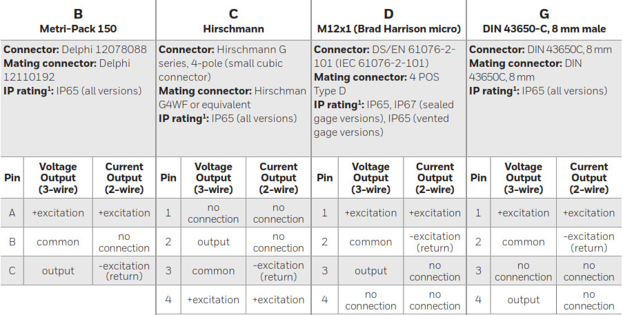

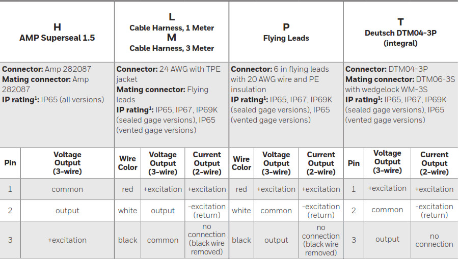
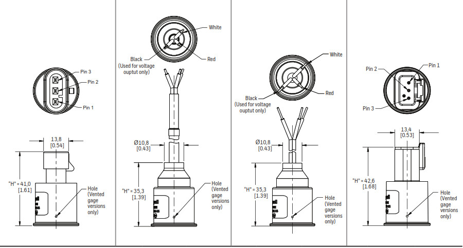
1 IP rating is determined by the electrical connector type chosen.2 Three-wire cable is required for ratiometric and regulated voltage outputs; two wire cable is required for current output.
Figure 4. Pressure Port Type Mounting Dimensions (For reference only: mm/[in].)1![]()
|
011/4-18 NPT |
061/8-27 NPT |
097/16-20 UNF 1/4 in 45ºFlare Female Schrader with depressor |
| Seal: Pipe threadMating geometry: ANSI B1.20.1-2013Installation torque: 2 to 3 turns from finger tight |
Seal: Pipe threadMating geometry: ANSI B1.20.1-2013Installation torque: 2 to 3 turns from finger tight |
Seal: 45º coneMating geometry: SAE J512Installation torque: 20 Nm [14.8 ft-lb] |
|
111/2-14 NPT |
13R1/4-19 (BSPT) |
19R1/8-28 (BSPT) |
| Seal: Pipe threadMating geometry: ANSI B1.20.1-2013Installation Torque: 2 to 3 turns from finger tight |
Seal: Pipe threadMating geometry: ISO 7-1Installation Torque: 2 to 3 turns from finger tight |
Seal: Pipe threadMating geometry: ISO 7-1Installation Torque: 2 to 3 turns from finger tight |
|
503/8-24 UNF (SAE J1926-2) |
517/16-20 UNF (SAE J1926-2) |
521/2-20 UNF (SAE J1926-2) |
| Seal1: O-ringMating geometry: SAE J1926-1Installation torque: 10 N m [7.4 ft-lb] |
Seal1: O-ringMating geometry: SAE J1926-1Installation torque: 20 N m [14.8 ft-lb] |
Seal1: O-ringMating geometry: SAE J1926-1Installation torque: 40 N m [29.5 ft-lb] |
|
539/16-18 UNF (SAE J1926-2) |
54M10x1.0 (ISO 6149-2) |
55M12x1.5 (ISO 6149-2) |
| Seal1: O-ringMating geometry: SAE J1926-1Installation torque: 45 N m [33.2 ft-lb] |
M10x1.0 (ISO 6149-2)Seal1: O-ringMating geometry: ISO 6149-2Installation torque: 20 N m [14.8 ft-lb] |
Seal1: O-ringMating geometry: ISO 6149-2Installation torque: 45 N m [33.2 ft-lb] |
|
56M14x1.5 (ISO 6149-2) |
57M16x1.5 (ISO 6149-2) |
58M18x1.5 (ISO 6149-2) |
| Seal1: O-ringMating geometry: ISO 6149-1Installation torque: 45 N m [33.2 ft-lb] |
Seal1: O-ringMating geometry: ISO 6149-1Installation torque: 55 N m [40.6 ft-lb] |
Seal1: O-ringMating geometry: ISO 6149-1Installation torque: 70 N m [51.6 ft-lb] |
|
59M20x1.5 (ISO 6149-2) |
60G1/8-28 (BSPP) DIN 3852-2 |
61G1/4-19 (BSPP) DIN 3852-2 |
| Seal1: O-ringMating geometry: ISO 6149-1Installation torque: 80 N m [59.0 ft-lb] |
Seal1: Bonded washerMating geometry with bonded washer:DIN3852-1; 2000-11, largeInstallation torque: 20 N m [14.8 ft-lb] |
Seal1: Bonded washerMating geometry with bonded washer:DIN 3852-1:2000-11, largeInstallation torque: 50 N m [36.9 ft-lb] |
| 62G1/8-28 (BSPP) ISO 1179-2 | 63G1/4-19 (BSPP) ISO 1179-2 | |
| Seal1: ElastomericMating geometry: ISO 1179-1Installation torque: 20 N m [14.8 ft-lb] |
Seal1: ElastomericMating geometry: ISO 1179-1Installation torque: 50 N m [36.9 ft-lb] |
1 Seal accessory included with transducer. Seal accessory material and specifications: O-ring (nitrile, durometer 90, temperature range -30°C to 125°C), bonded washer (steel outer ring with nitrile inner ring, temperature range -30°C to 125°C), elastomeric seal (nitrile, temperature range -30°C to 125°C).
![]() WARNINGPERSONAL INJURYDO NOT USE these products as safety or emergency stop devices or in any other application where the failure of the product could result in personal injury.Failure to comply with these instructions could result in death or serious injury.
WARNINGPERSONAL INJURYDO NOT USE these products as safety or emergency stop devices or in any other application where the failure of the product could result in personal injury.Failure to comply with these instructions could result in death or serious injury.
Warranty/RemedyHoneywell warrants goods of its manufacture as being free of defective materials and faulty workmanship during the applicable warranty period. Honeywell’s standard product warranty applies unless agreed to otherwise by Honeywell in writing; please refer to your order acknowledgment or consult your local sales office for specific warranty details. If warranted goods are returned to Honeywell during the period of coverage, Honeywell will repair or replace, at its option, without charge those items that Honeywell, in its sole discretion, finds defective. The foregoing is buyer’s sole remedy and is in lieu of all other warranties, expressed or implied, including those of merchantability and fitness for a particular purpose. In no event shall Honeywell be liable for consequential, special, or indirect damages.
While Honeywell may provide application assistance personally, through our literature and the Honeywell web site, it is buyer’s sole responsibility to determine the suitability of the product in the application.
Specifications may change without notice. The information we supply is believed to be accurate and reliable as of this writing. However, Honeywell assumes no responsibility for its use.
For more information
Honeywell Advanced Sensing Technologies services its customers through a worldwide network of sales offices and distributors. For application assistance, current specifications, pricing or the nearest Authorized Distributor, visit our website or call:
Asia Pacific +65 6355-2828Europe +44 (0) 1698 481481USA/Canada +1-800-537-6945
Honeywell Advanced Sensing Technologies830 East Arapaho RoadRichardson, TX 75081 sps.honeywell.com/ast50010132-E-EN | E | 05/21© 2021 Honeywell International Inc.![]()
References
[xyz-ips snippet=”download-snippet”]