Read and understand this manual and all safety signs before using this appliance. Keep this manual for future reference.
DESCRIPTION
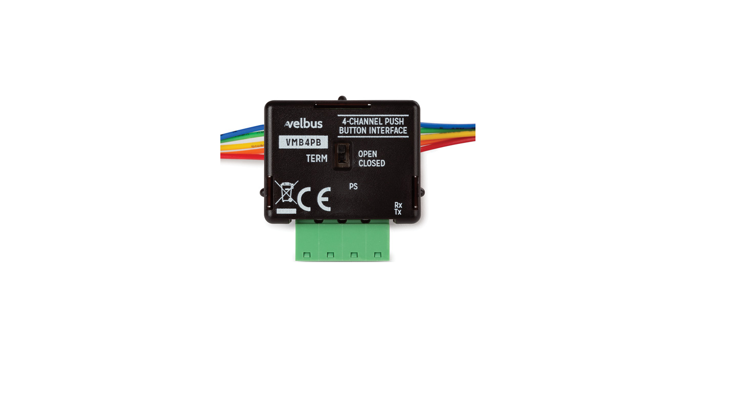
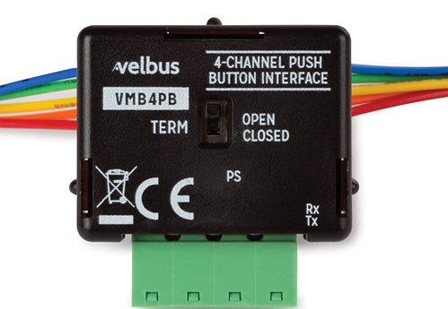
4-channel push button interface
USE AND CONFIGURATION
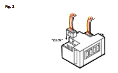
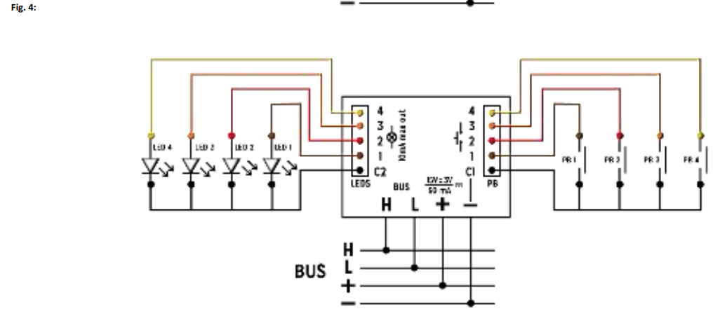
Push button interface for connecting up to 4 push buttons (with optional feedback LEDs) to the Velbus home automation system. Configure using the Velbus configuration software VelbusLink. (See installation guides on www.velbus.eu.)Both LEDs with common anode and with a common cathode can be connected (configurable in VelbusLink). Connection of LED connectors (optional): see fig. 2.Advanced: the VMB4PB can be used as an I/O module, which LED outputs can be connected to the control outputs of another system (considering the specifications indicated below). To do so, configure the VMB4PB as an I/O module in VelbusLink, and assign actions to the output channels.STATUS LEDs:
- PS LED: power voltage detected
- Rx LED: CAN bus packet received
- Tx LED: CAN bus packet sent
CONCISE TECHNICAL SPECIFICATIONS
- Power supply: 15 ± 3 VDC
- Max. current consumption 50 mA
- Dimensions: 36 x 38 x 16 mm (L x W x D)
- Protection rating: IP10
LED outputs:
- max. output voltage 15 VDC, suitable for LEDs up to 24V (AC or DC)
- built-in series resistor: 1.5k Ω
- max. output current: 10 mA @ 15 V
For a detailed list with technical specifications, please refer to the product page on www.velbus.eu.CONNECTION DIAGRAMS
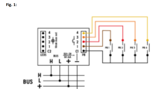
- A. Connection of push buttons without LEDsSee fig. 1

- B. Connection of the LED connectors (necessary only for push buttons with LEDs)See fig. 2

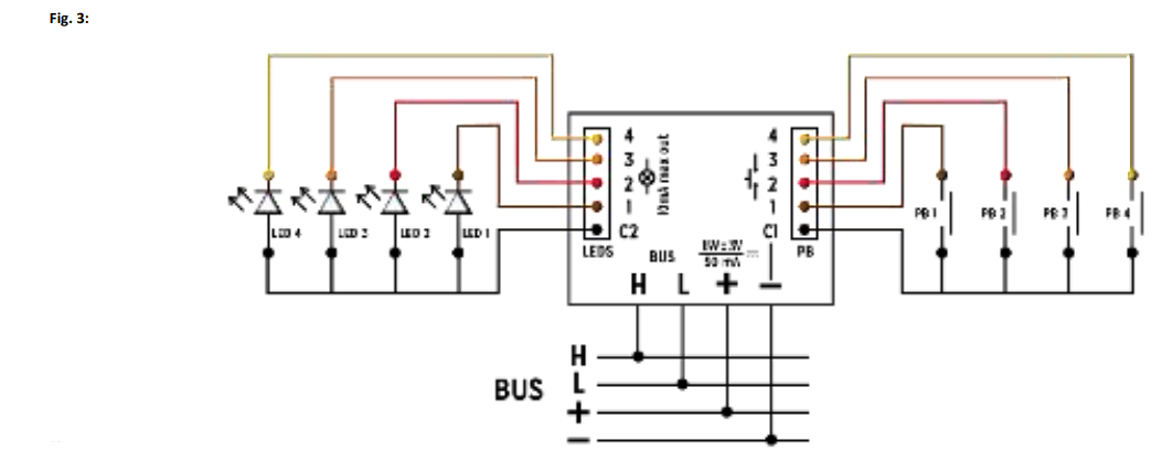
- C. Connection of the push buttons and LEDs with common anodeSee fig. 3

- D. Connection of push buttons and LEDs with common cathodeSee fig. 4

This product complies with all of the relevant European guidelines and regulations.
Velbus – Legen Heirweg 33, BE-9890 Gavere, Belgium – tel. +32 9 384 36 11 – e-mail: [email protected] – www.velbus.eu
References
[xyz-ips snippet=”download-snippet”]

