![]() 201052A,BAuxiliary SwitchINSTALLATION INSTRUCTIONS
201052A,BAuxiliary SwitchINSTALLATION INSTRUCTIONS
This is a legacy product document supported by Resideo. It is no longer manufactured
APPLICATION
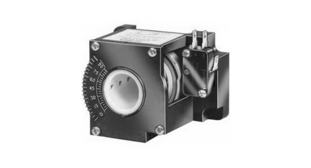
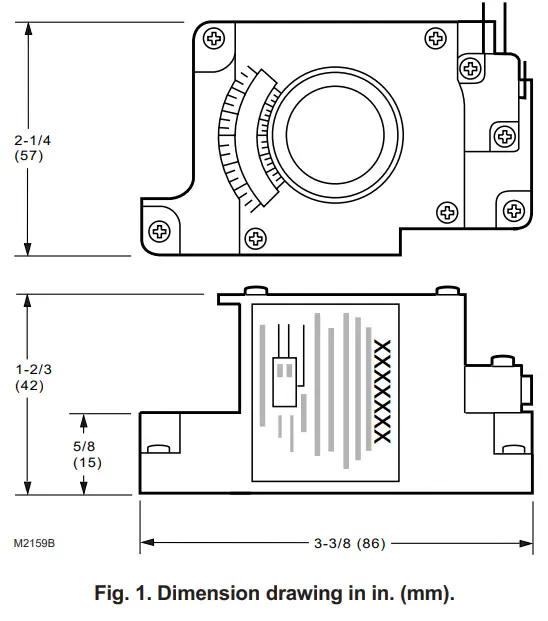
The 201052A or B Auxiliary Switch is used in conjunction with the ML6161/ML7161 Direct Coupled Actuator. It allows for control of equipment external to the actuator (for example, electric reheat coils and fan) at an adjustable point in the actuator stroke (from 0¡ to 90¡).Models:201052A: Contains one auxiliary switch.201052B: Contains two auxiliary switches.Electrical Ratings:50 VA, pilot duty at 24 Vac, selective, not simultaneous.Switching:Single-pole, double-throw (spdt) micro switches.Switch Differential:Three angular degrees maximum.Approvals:Underwriters Laboratories Inc. Recognized: File No.E4436, Guide No. XAPX.Dimensions:See Fig. 1.
INSTALLATION
When Installing this Product…
- Read instructions carefully. Failure to follow them could damage the product or cause a hazardous condition.
- Check ratings and descriptions given in specifications to make sure the product is suitable for your application.
- The installer must be a trained, experienced service technician.
- After installation is complete, check out product operation as provided in these instructions.
 CAUTION Electrical Shock or Equipment Damage Hazard.Can shock individuals or short equipment circuitry.Disconnect power supply before installation.Actuators with auxiliary switches can have more than one disconnect. CAUTION Actuator Damage Hazard.Turning motor output hub by hand or wrench can damage internal gears.Ensure declutch button is depressed while manually turning the hub.
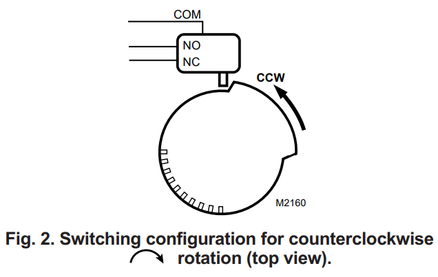
- Determine desired to switch action (if the switch is to energize during
 clockwise or counterclockwise rotation). With switch cam as shown in Fig. 2, the normally closed contact opens during counterclockwise rotation and the normally open switch closes. Conversely, with the switch cam as shown in Fig. 3, the normally closed contact opens during clockwise rotation and the normally open switch closes.
 - Align the switching hub with the set screws on the actuator. See Fig. 4. Mount the switch on the actuator and tighten the three captive screws.
- Engage the declutch and rotate the hub to the desired position for switch operation.NOTE: When installed, the angular position indicator on the switch face moves from 90¡ to 0¡ during counterclockwise motion and from 0¡ to 90¡ during clockwise motion.
- Disengage declutch.
- With a screwdriver, move the cam inside the switch assembly to the appropriate position. Remember, the direction of travel of the cam for switching purposes (see Fig. 2 and 3). Monitor the switch closure with an ohmmeter for a continuity check. See Table 1.
 Conversely, with the switch cam as shown in Fig. 3, the normally closed contact opens during clockwise
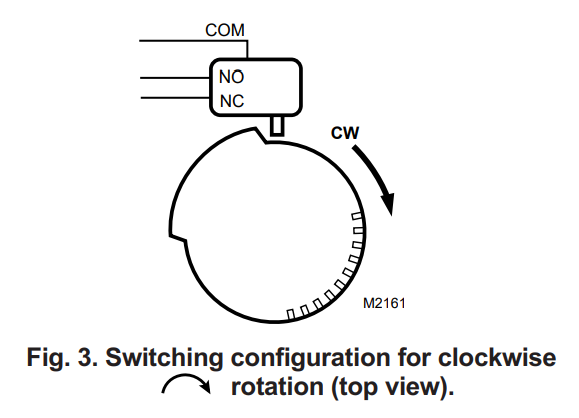
IMPORTANTMake certain that the switch activates at the desired degree of stroke.NOTES:– For two switch models, cams align with their respective switches and are each individually set using the same procedure described in the Installation section.– Switches may also be preset prior to installation on the actuator if the angular switch position is known.
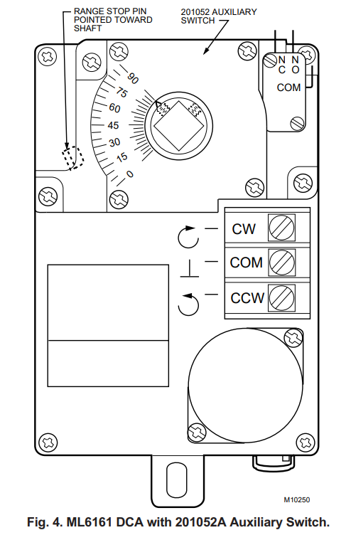
Table 1. Proper continuity measurements.
| Normally Open Contacts | Normally Closed Contacts | |
| Switch Activated | Zero ohms | Infinite ohms |
| Switch Not Activated | Infinite ohms | Zero ohms |
![]()
| Home and Building ControlHoneywell Inc.Honeywell PlazaP.O. Box 524Minneapolis, MN 55408-0524 | Home and Building ControlHoneywell Limited-Honeywell Limitée155 Gordon Baker RoadNorth York, OntarioM2H 3N7 |
Helping You Control Your World®By using this Honeywell literature, you agree that Honeywell will have no liability for any damages arising out of your use or modification to, the literature. You will defend and indemnify Honeywell, its affiliates and subsidiaries, from and against any liability, cost, or damages, including attorneys’ fees, arising out of, or resulting from, any modification to the literature by you.63-2218—1 B.B. Rev. 10-97 Printed in Mexico®U.S. Registered TrademarkCopyright © 1997 Honeywell Inc.  • All Rights Reserved

[xyz-ips snippet=”download-snippet”]