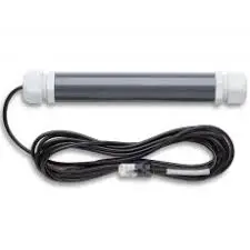
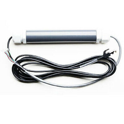
Onset R.M. Young Marine Wind Sensor Adapter S-WCC-M003


This document provides instructions for connecting the R.M. Young 05106 Marine Wind Sensor to the S-WCC-M003 Onset adapter to allow the wind sensor to be used with a smart sensorcompatible HOBO® station.Note: Refer to the R.M. Young instruction manual for your wind sensor for additional information as needed.
Tools Required:
- Screwdriver
- 27 mm (1-1/16 in) wrench (or adjustable wrench)
Specifications


A single HOBO station can accommodate 15 data channels and up to 100 m (328 ft) of smart sensor cable (the digital communications portion of the sensor cables). Smart Sensor Extension Cable Part No. S-EXT-M0xx
Measurement Operation
Wind speed and direction measurements are averaged over the logging interval or a 3-second timeframe (whichever is greater). If you set up the sensor to log faster than every 3 seconds, the same sensor reading will be recorded until a new 3-second average is calculated. For example, if the sensor is logging at a 1-second interval, the sensor will report the same wind speed and direction (its calculated average) for three samples before calculating and reporting a new value for another three samples. Gust speed is the highest three-second wind recorded during the logging interval.
Direction Averaging
Unit vector averaging is used to determine wind direction because traditional averaging would produce inaccurate results. For example, three measurements of 350, 11, and 12 degrees— which are all winds from the north—averaged together would result in 126 degrees, which incorrectly indicates a southeasterly wind. Instead, the vector components (North/South and East/West) for each wind measurement are calculated every three seconds for the duration of the logging interval. At the conclusion of the logging interval, the North/South and East/West components are averaged and then re-combined to calculate the average wind direction for the logging interval.
Connecting the Wind Sensor to the Adapter
Step 1: Drill Grommet
The grommet on the non-cable end of adapter housing must be drilled in order to accept the cable from the wind sensor. Unscrew the grommet from housing. Next, accurately measure the diameter of the wind sensor cable’s jacket (diameters varyfrom sensor to sensor) and then drill a hole through the center of the grommet’s rubber insert. The diameter of the hole should only be just large enough for the cable to pass through. Clean out any debris from the insert. Note: To facilitate drilling, we recommend putting the grommet into a freezer for about two hours before drilling to stiffen the rubber, and then to use a sharp drill.
Step 2: Grease Drilled Grommet and Install onto Wind Sensor Cable
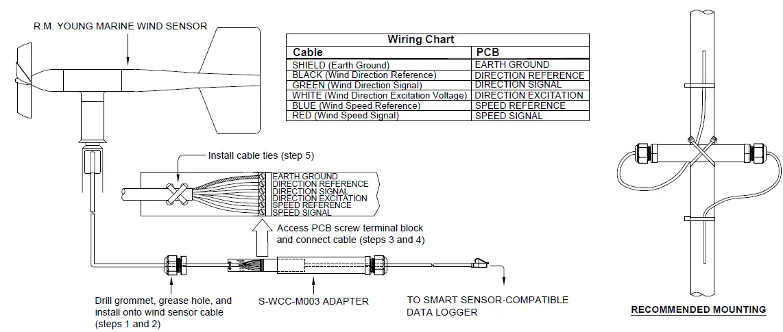
Using supplied packet, apply a coating of grease to the drilled hole of grommet from step 1 and then slide grommet onto wind sensor cable jacket in orientation shown below (loosen grommet’s dome nut if necessary).
Step 3: Access PCB Screw Terminal Block
Loosen dome nut on grommet where the black modular jack cable exits the adapter housing (do not unscrew the grommet body itself from housing), then gently push cable through housing until the screw terminal block is accessible on the PCB.
Step 4: Connect Wind Sensor Cable to Screw Terminal Block
Connect shield and wires to PCB screw terminal block as shown in diagram below. Be sure wires are fully secured in the terminals.
Step 5: Secure Cable to PCB
Feed supplied cable ties through holes at end of PCB in a crossing pattern, then tighten around cable jacket and trim ends.
Step 6: Re-assemble Adapter
Gently pull PCB back into adapter housing. Slide grommet down the wind sensor cable and then use wrench to fully tighten grommet body into the housing. Next, hand tighten dome nut onto body and then use wrench to tighten an additional ½ turn. Dome nut must be snug, but should not be over tightened. Finally, in a similar manner, re-tighten dome nut loosened in step 3.
Step 7 – Mount the Wind Sensor
The diagram below shows the recommended mounting for the wind sensor. Secure the adapter to the mast with two cable ties crossed together. Be sure to put drip loops on either side of the adapter housing as shown below to protect the adapter from water. Secure the cables to the mast with cable ties at the end of each drip loop.


[xyz-ips snippet=”download-snippet”]

