AAI Vector Impedance Analyzer User Manual
Product Introduction
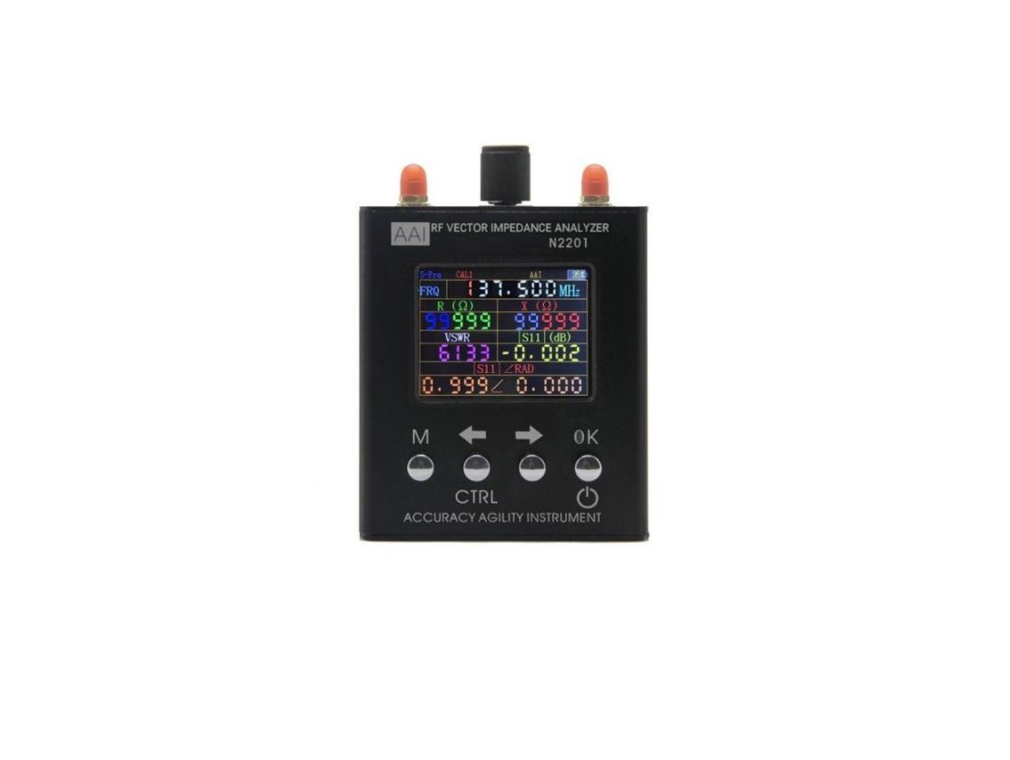
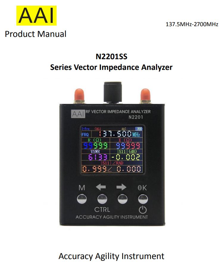
N2201SS vector impedance analyzer is mainly used for testing the antenna, RF component impedance and the circuit board impedance. With built-in high-capacity lithium-ion battery, N1201SA series product is small enough to be placed in the pocket and really convenient for outdoor and high-altitude special operations. Clear and simple display screen interface and button operation make it easy to use as well.N2201SS is equivalent to enhanced N1201SA and then add a RF power meter function. The detection range of the RF power meter is -20dBm +8dBm, and the detection accuracy is <±1dBInput power 0dBm ~ +8dBm.This power meter can be applied directly to the measurement of small power and micro power communication equipment. High power equipment needs to be used with couplers or attenuators.
Main Features:
- Wide frequency range:137.5 MHz to 2700 MHz
- Small size: 9 * 10 * 2.8 (cm); light weight (net weight): 240g
- Built-in 2000mAH polymer lithium battery, continuous working time more than 4 hours.
- High resolution, 4 significant figures (single point measurement).
- With calibration function, accurate measurement is guaranteed.
- Cost-effective.
Notes
- Calibration Kit need to be purchased separately.
- Power-On Hold down the CTRL key and press OK to turn on.Power-Off Press and hold (> 2S) to turn off the instrument.
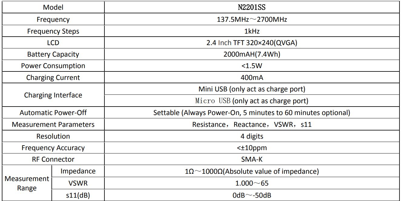
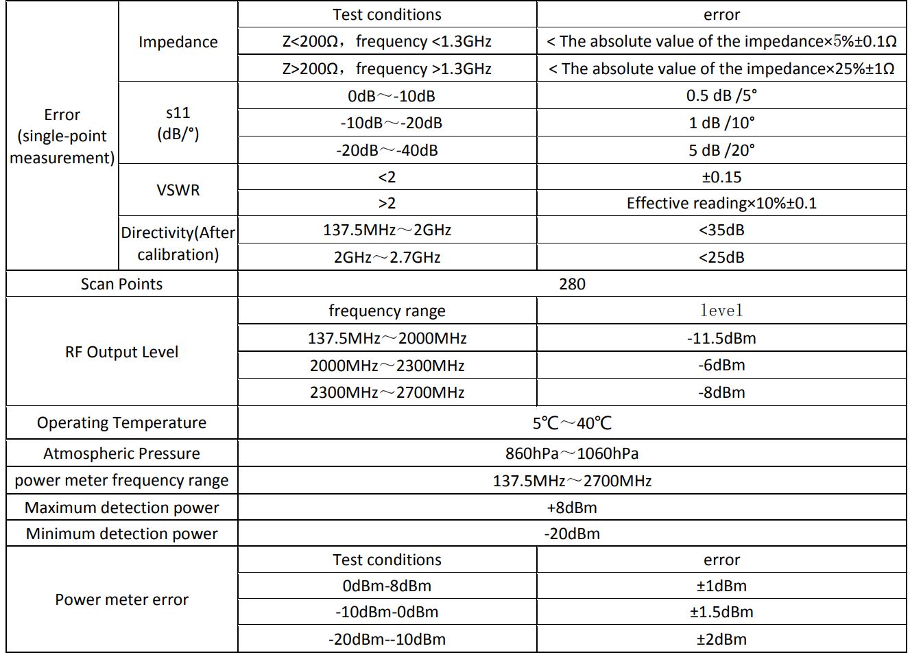
Technical indicators
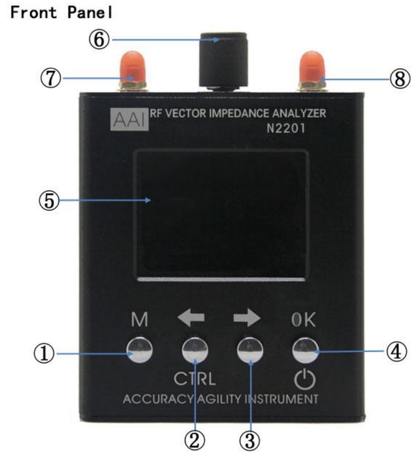
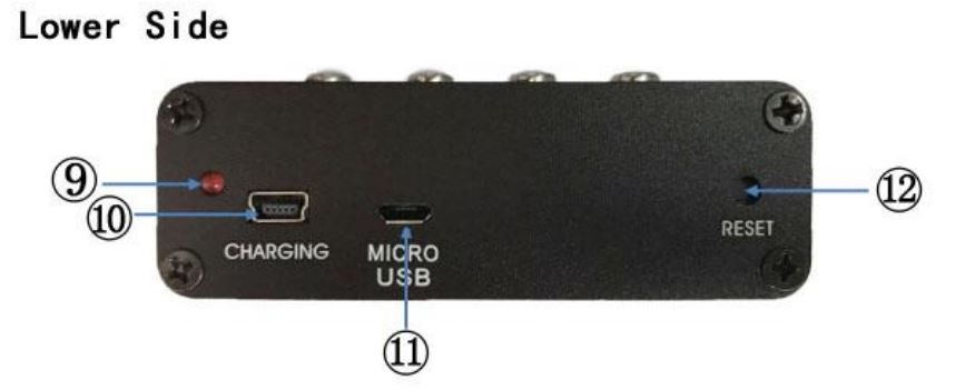
Body Description
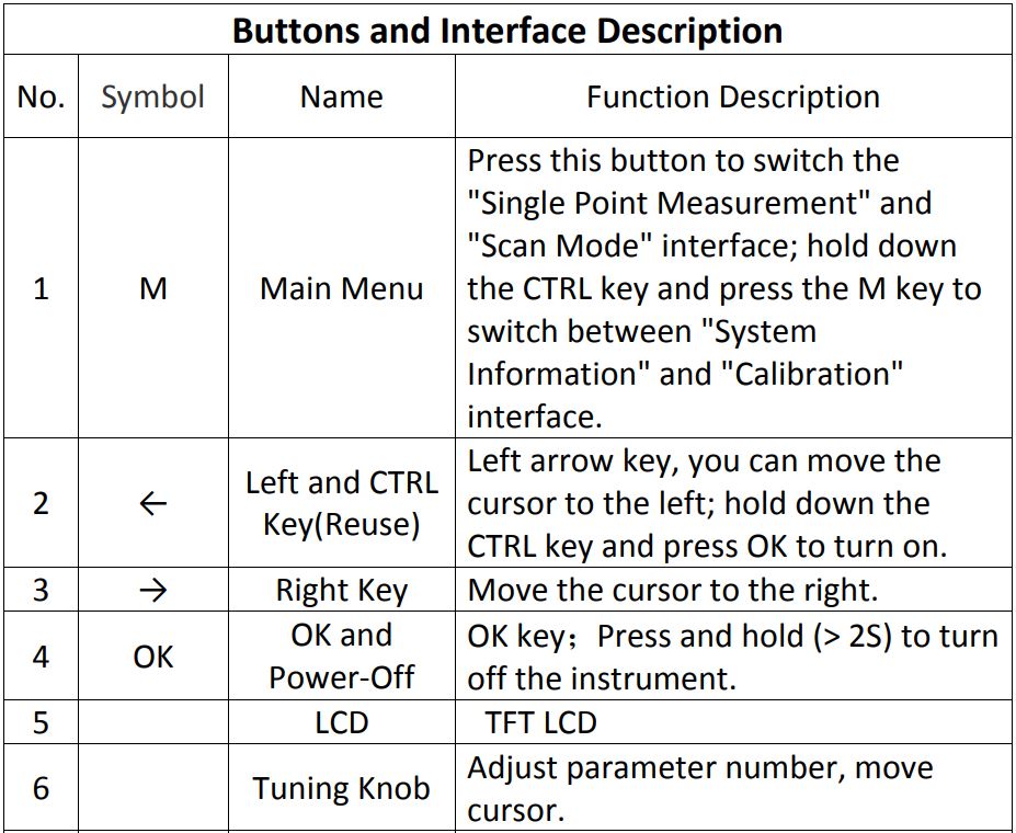
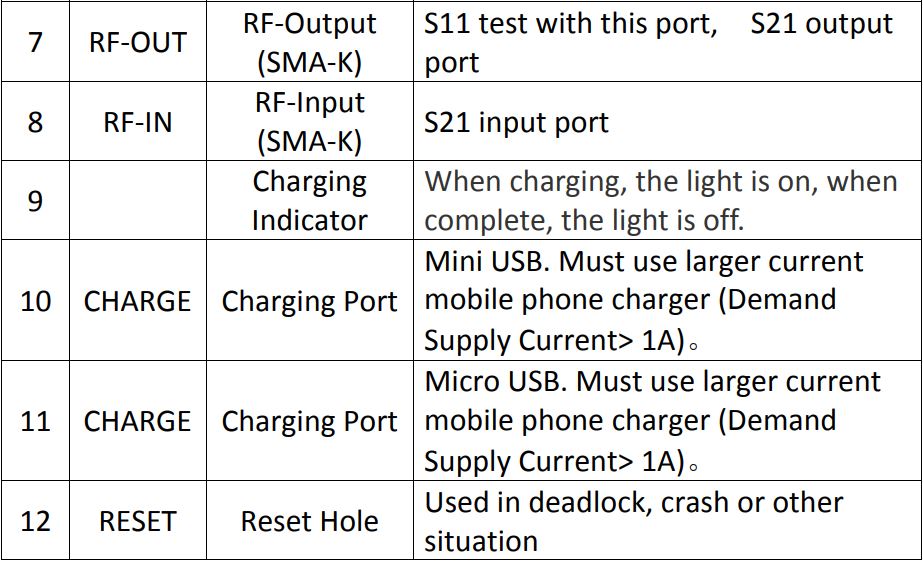
Function Description
There are four basic operational interfaces including Single Point Measurement, Scan Function, Power meter Measurement System Information and Calibration. The default interface after power-on is Single Point Measurement.
1. Single Point Measurement
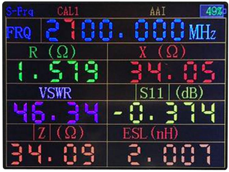
This interface is used for measuring the fixed frequency point.Only frequency parameters can be adjusted in this interface. Press Right or Left key to select the digit you need to adjust, once selected, the digit will turn red, and the digit can be modified by turning the knob. After adjusting the frequency, the measuring result will automatically update.Note: How to adjust values in other place of this product is the same as above.Press OK button under Single Point Measurement mode, you can switch impedance and S-parameter measurements and capacitance and inductance measurements.
2. Scan Function
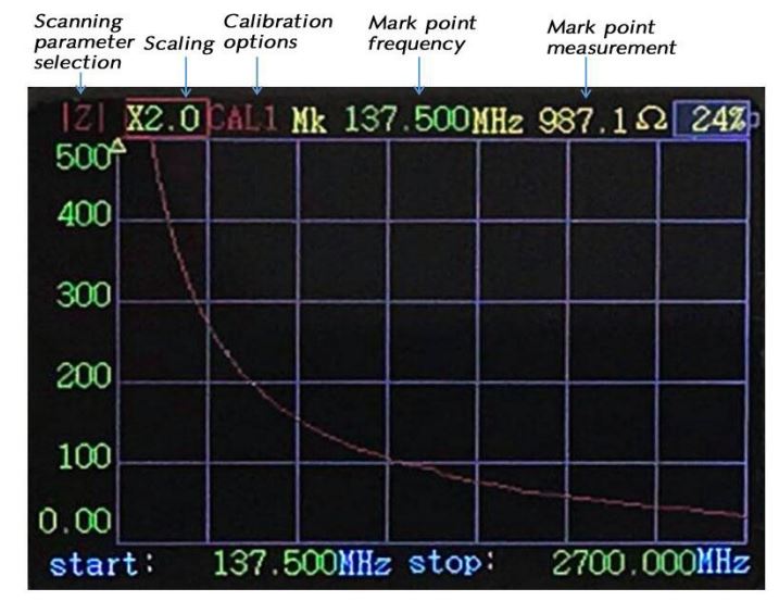
Press M key under Single Point Measurement mode, it will switch to the Scan Function interface.Five type parameters of Scan Function can be modified.Scan Parameters Types There are five scanning parameters including S11, VSWR,| Z|, R, X,Scaling: Scaling shows the Y-axis, and can be adjusted based on the measured valueMark Points Frequency: Scan mark points frequency of the graphicStart Frequency: Start frequency of the scanEnding Frequency: Ending frequency of the scan
Selecting Mode and Adjusting Mode are two different modes as adjusting the parameter, you can press OK key to switch between them. Under Selecting Mode, press Right/Left key or turn the Knob to select the parameter you need to adjust, once selected, the parameter will turn red (The original color of Start Frequency , Ending Frequency and Mark Points Frequency turn to red indicates the parameter is selected) or there will show a red box (Scan Parameters Types or Scaling). After press OK key, it will switch to Adjusting Mode, the red box of the selected parameter (Scan Parameters Types or Scaling) will turn to yellow; one of the digit of parameter (Start Frequency, Ending Frequency and Mark Points Frequency) will turn red. The method of adjusting parameter here is as same as that in Single Point Measurement: Select digit by pressing Right/Left key, modify the value by turning the knob(Knob button can be pressed as well, and the function of which is the same as OK key, when selecting parameter, you can press knob button directly)When using, please pay attention to adjusting the scaling in terms of different measuring values, it won’t show the accurate result if the scaling is inappropriate.The measured value of the Mark Point in the Scan Function is different from the value in the Single Point Measurement. In fact, the measured frequency of the Mark Point is not exactly the accurate frequency at this point, but the closest value of the scanning frequency. For example, scan the frequency from 1000MHz to 1280MHz, Mark Point Frequency is set to 1200.45MHz, the actual measuring value is 1200MHz which is the closest to 1200.45MHz. If this frequency is just a sensitive point, there will be a big difference. However, there are two ways to find out the accurate value: One is subject to Single Point Measurement, the other is to minimize the scan bandwidth.
3. Power measuring
![]() Ensure that the power of input the power meter is not more than 10dBm
Ensure that the power of input the power meter is not more than 10dBm
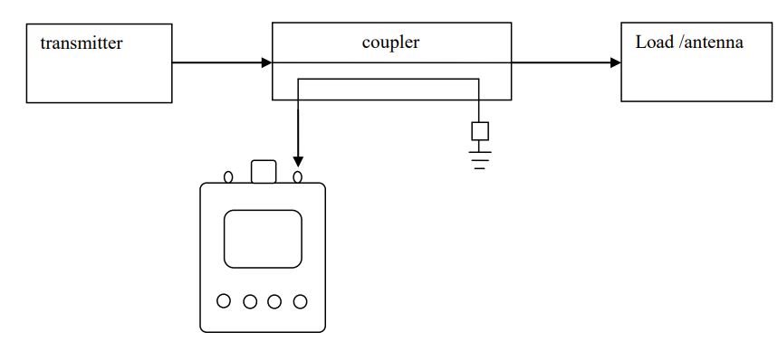
The Power Meter can only measure directly small power <10dBmthat is<10mWWhen Power is more than 10mW it needs to be used with the attenuator or coupler to ensure that the power of entering the Power Meter is not more than 10mW.The following is a diagram of the power measurement using a coupler
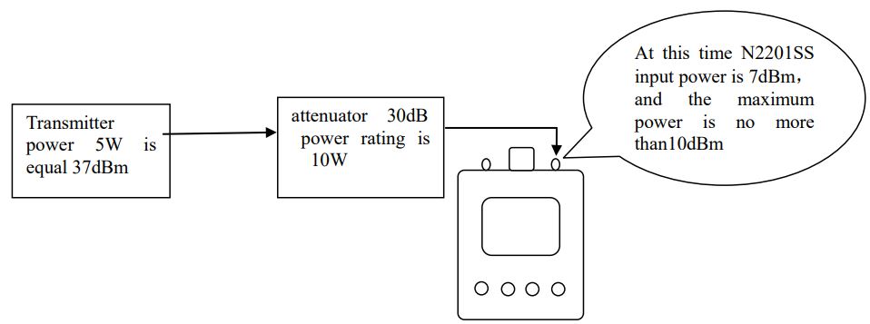
The following is a diagram of the power measurement using the attenuator
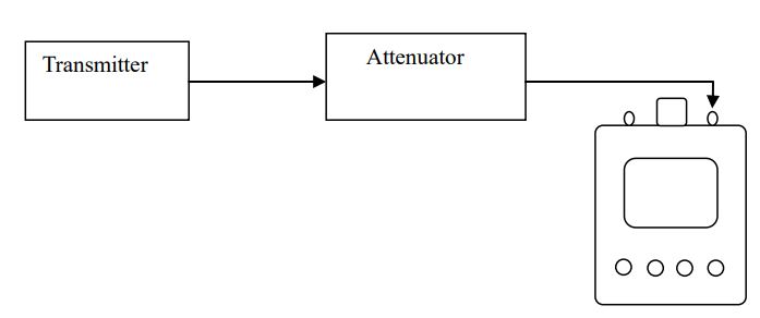
For example, to measure the power of a 5W transmitter, 5W=37dBm, in order to make the input power within the measurement range, Transmitter output needs to enter a power meter through at least 30dB attenuator or coupler. In addition, when the attenuator is used, the power and heat dissipation of the attenuator must be confirmed. At least 10W or more power attenuators are used for 5W signals.
As shown in the following figure
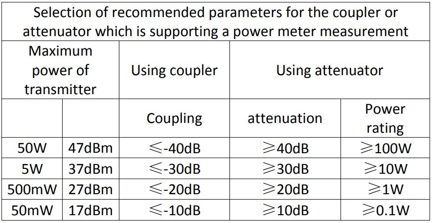
When measuring power, the attenuator or coupler can be selected from the following table
Note: when using the power measurement function, the measured Signal is connected to the SMA port on the right side. The result of the measured value of the power meter is true rms. The interface for power measurement is as follows:
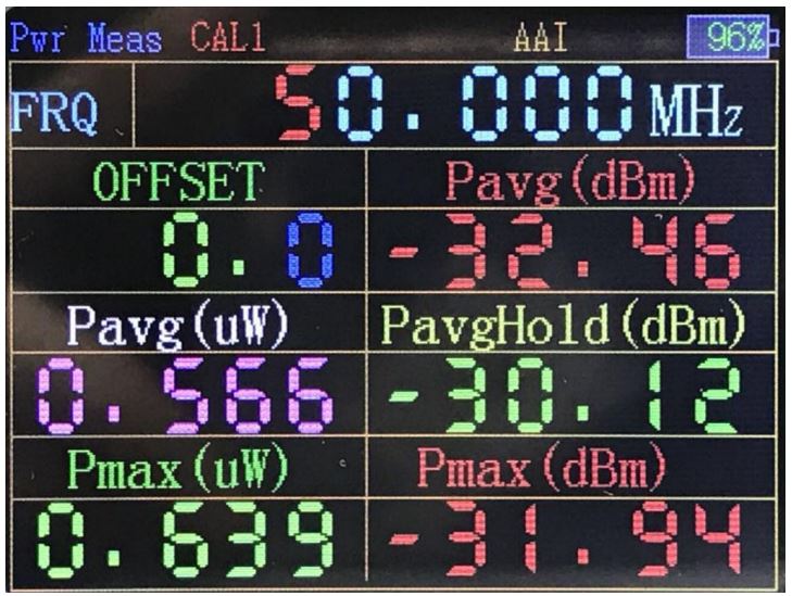
Change the measurement frequency and offset by OK keyThe results of different frequency measurements are different, so it needs set to the specified frequency.
Different frequency measurement results will have differences, so it is basically set to the specified frequency. “offset” is used when correcting errors or converting external attenuators or amplifiers. For example, the signal enters the instrument through a 30dB attenuator. The offset is set to 30dB. If a 30dB amplifier enters the instrument, the offset is set to -30dB.This parameter can also be set to compensate if errors are found in the measurement of the instrument itself.
“Average power (dBm)” is the dBm readings of the average after measuring 200 times. “Average power” is the reading when the reading is converted to MW. “Average power” is the reading when the reading is converted to W.
The power hold: it is keeping display measured the average power value, so it is easy to capture the pulse power signal.
Maximum power (dBm) “is to take the largest value of all measured values ( dBm) reading. “Maximum power (mW)” is the readings converted to mW. Click the OK key to reset the maximum value.
4. System Information
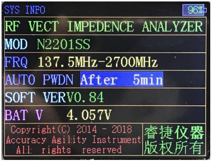
In Single Frequency mode or Scan Function interface, hold down the CTRL key (left), then press the M key, you can switch to the System Information interface.System information is mainly about the product, among which, automatic Power-Off parameter can be modified by turning the knob or pressing the Left/Right key. After modification it will come into effect immediately. Press OK key to save the parameter status.
5. Correction and Calibration
![]() Special Announcement: Before illustrating how to do thecalibration, you have to know that if you don’t have calibrating kit in hand, you must not do it, because the device has been calibrated to SMA port during production , Just use it directly.
Special Announcement: Before illustrating how to do thecalibration, you have to know that if you don’t have calibrating kit in hand, you must not do it, because the device has been calibrated to SMA port during production , Just use it directly.
In what circumstances need to be calibrated:
- If you need to do a precise measurement, please use calibration kit.
- The measured object is not directly connected to the product port, but after a period of cable, and you need to measure the resistance, reactance or other parameters of the measured object.
Special Attention:Red “CAL 0” marked on the product means using the system calibration parameters that is the calibrated port is just at the RF port of the product. “CAL 1” means using the user calibration data.If using adapter, in the case of low frequency, there is no need to do calibration.
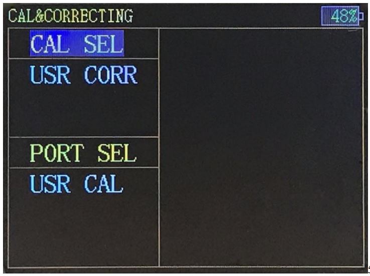
First, there is necessary to explain the distinction between correction and calibration. For those who have used the vector network must know that accurate measuring of the RF impedance of the DUT requires the calibration of the test cable, but they may not know clearly about correction.Calibration means after connecting the test cable with the device, use calibration kit to calibrate the cable and then keep the calibrating results (i.e.. Calibration meters) ,which if used to correct the measurement results as using the test cable to test the measured object, the measurement result is corrected, and vice versa. In other words, correction means whether or not use calibration parameters to correct the measurement result when testing the measured object.Hold down the CTRL key and press the M key at System Information Interface, you will switch to the Correction and Calibration interface.Correction Option located in the upper left side of the interface, and there are two options for now, one is “System Correction”, the other is “User Correction “. When selecting “System Correction”, the measurement standard is at the SMA port of the product.Calibration Option located in the lower left side of the interface. Press the left/right key to switch between Correction and Calibration, and turn the knob to select a specific item. After selecting the Calibration, press “OK” to start.Note: The calibration is irreversible, because once the calibration is starting the previous calibration data has been cleared and completing the whole calibration process is necessary.The calibration of this product is based on SOL which is short circuit (SHORT), open circuit (OPEN), and load (LOAD).
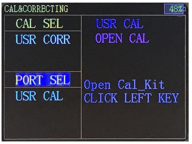
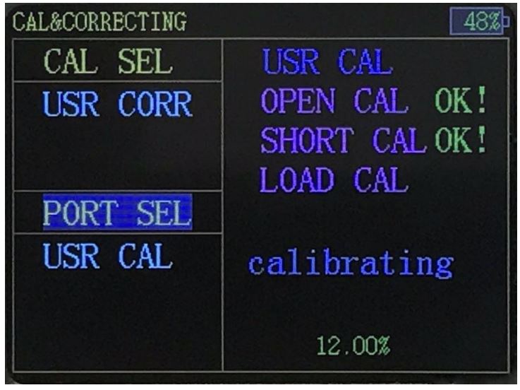
Calibration Process:Select Highlight when the “Port Calibration” item is selected, and then press “OK” key to start.After entering calibration, there is a preparation process and then it will show a prompt message “OPEN CAL”. Please connect the OPEN CAL and press the left button to start calibration.
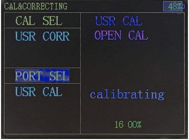
 The calibration process takes times
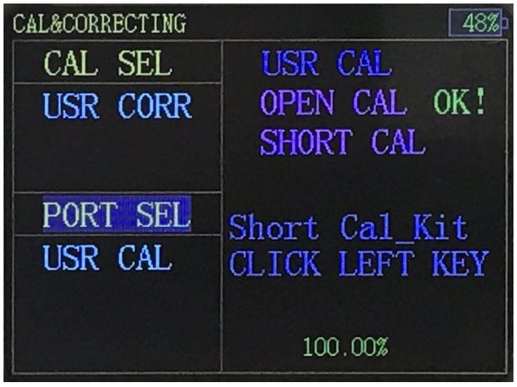
Followed by short-circuit calibrationThere is a preparation process and then it will show a prompt message “SHORT CAL”, Please connect the SHORT CAL and press the left button to start calibration.
Followed by standard load calibrationThere is a preparation process and then it will show a prompt message “LOAD CAL”, Please connect the LOAD CAL and press the left button to start calibration.
All calibration is done
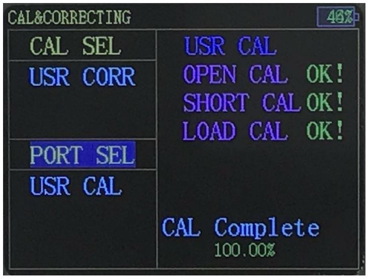
Note: For user convenience, the Correction Option is automatically changed to User Correction during every calibration. At the same time, in order to ensure the integrity of the calibration, automatic power-off function is invalid and the device will keep power-on.
Security Requirements
1. Charge
This device is not equipped with charger, please use mobile phone or tablet charger with current 1A or more to charge. As the power consumption of the device is large, so as the battery capacity is large, the charge current is designed to be limited within 400mA, and after completely discharged, it will take about 5 hours to fully charge. If the charge is in the boot state, the overall current consumption is about 750mA, so in order to charge it right, please use the charger with current output capacity more than 1A. Please charge in time to avoid battery damaging, and do not use computer USB which current is insufficient to support the device and it may cause computer work abnormal. In addition, the power indication of the product is indicative and the error will be more obvious especially in charging. Error within 15% is normal please beware that is not battery damage or product broke down.
2. Storage
There is lithium polymer battery within the device, so please store it after full charge and power off. We kindly recommend that if long-term unused, you may need to charge every other year to keep the battery far from damage.We use USB plug for charging port but not USB communication interface. Connect it to computer USB will bring interference signal, affect normal work.
3. Transport
Shockproof and drop packaging are necessary in transport. Within batteries, we kindly recommend land or water transportation.
Cautions
- In order to ensure the accuracy of the measurement and calibration, please preheat the product for at least 5 minutes, especially when calibrating, preheating will make it more accurate.
- Battery-powered, the internal noise of product is minimal. It is recommended that measure in case of battery-powered is better. When connecting charger, if the charger quality is not good, there will be some noise.
- Do not use computer USB to charge, because the product power consumption exceeds USB power supply restrictions, besides, USB port signal will seriously interfere product’s working state, and result in inaccurate measurement.
- Please try using high-quality RF cables and connectors
- Over length test cable will cause inaccurate measurement, so it is recommended that do not use over length test cable.
- Low-quality or damaged test cable and RF connector will significantly affect the accuracy of the measurement results, so the cable and the connector must be ensured to be intact during the test.
- Before measuring and calibrating, make sure there is no strong wireless signal around, for fear of interfering with the measurement results.
- If you do not understand the impedance measurement itself, you can refer to the vector network analyzer instructions and tutorials. This product is equivalent to single-port vector network analysis.
- When the battery is less electricity, please charge in time.
- RF interface is SMA-K, because the strength of copper is lower than other metals, please try to protect it carefully, avoid falling, bumping or damaging.
- The RF port of the product could not be poured into high power, the power limit is 0dBm. From initial calculation, if there is a 5W radio launch signal within 6 meters, and the product is also connected to the antenna, the product is likely to be burned As the use of Walkie talkie are more casual, so this situation need to be carefully noticed.
- In the case of strong interference, unconventional operation, and unknown software bug, there may be a crash situation, after the crash it may be drained on the battery until it runs out. In this situation, please reset the product directly to avoid battery damage. If the battery is exhausted, the battery is extremely low, charging current will be very large, the power supply current charger will be in short-circuit protection, but please continue to charge until the battery can be charged.
After-sales Service
After the product is sold, the product cannot work normally as its own problem within one year .AAI offers free maintenance or replacement service. AAI provides lifelong technical support as well.
Contact us
AAI commit to provide lifelong technical support for our product. Should you have any questions or inquires during the use of the product or this manual, please feel free to contact us:TEL: 15010971271QQ: 493299523E-mail: [email protected]SINA BLOG: http://blog.sina.com.cn/u/5635362932
References
[xyz-ips snippet=”download-snippet”]