ABUS Nexello 3I 3O Hybrid Module User Manual

IntroductionDear customer, dear customer, we are pleased that you have decided to use our product and thank you for your trust! You have made a good choice. This hybrid module (hereinafter referred to as “device”) has been developed and manufactured with the greatest care. Please read this operating manual in its entirety and observe all operating and safety instructions, as this ensures the best possible handling of the device. This document is to be considered as assembly and maintenance instructions.
Hereby ABUS Security-Center declares that the enclosed product complies with the following guidelines concerning the product:RED Directive 2014/53/EU, EMC Directive 2014/30/EU, Low Voltage Directive 2014/35/EU, RoHS Directive 2011/65/EU. The full text of the EU Declaration of Conformity is available at the following Internet address
www.abus.com/product/PLHA10100It can also be obtained from the following address:ABUS Security Center GmbH & Co KG,Left Kreuzweg5, 86444 Affing, GERMANY
If you have any questions or suggestions, please contact our customer service:
Mail: ABUS Support, Linker Kreuzweg5, 86444 Affing, GermanyE-mail: [email protected]Phone: +49 8207 959 90 0Opening hours hotline: Mon-Thu: 08 – 17 hrs.; Fri: 08 – 14 hrs.
All company names and product designations contained herein are trademarks of their respective owners. All rights reserved.
![]() DisclaimerThis operating manual has been prepared with the utmost care. Should you nevertheless notice any omissions or inaccuracies, please notify us in writing at the address given above. Your rights are limited to the repair or replacement of this product in the condition it was delivered. ABUS Security Center assumes no liability for any special, incidental or consequential damages, including but not limited to loss of revenue, loss of profits, restrictions on use of the software, loss or recovery of data, cost of replacement equipment, downtime, property damage and claims by third parties, as a result of, and without limitation, the use of the software. contractual, statutory or damage compensation claims arising from the warranty, irrespective of other limited warranty provisions or those implied by law, or in the event that the limited warranty does not apply, the scope of liability of ABUS Security Center is limited to the purchase price of the product. The contents of this manual are subject to change without prior notice. © ABUS Security-Center GmbH & Co KG, 09/2019
DisclaimerThis operating manual has been prepared with the utmost care. Should you nevertheless notice any omissions or inaccuracies, please notify us in writing at the address given above. Your rights are limited to the repair or replacement of this product in the condition it was delivered. ABUS Security Center assumes no liability for any special, incidental or consequential damages, including but not limited to loss of revenue, loss of profits, restrictions on use of the software, loss or recovery of data, cost of replacement equipment, downtime, property damage and claims by third parties, as a result of, and without limitation, the use of the software. contractual, statutory or damage compensation claims arising from the warranty, irrespective of other limited warranty provisions or those implied by law, or in the event that the limited warranty does not apply, the scope of liability of ABUS Security Center is limited to the purchase price of the product. The contents of this manual are subject to change without prior notice. © ABUS Security-Center GmbH & Co KG, 09/2019
Important Safety InstructionsAppropriate useUse the device exclusively for the purpose for which it was built and designed! Any other use is considered improper! The product is designed exclusively for indoor wall mounting.Damage caused by not following these safety instructions invalidates the warranty. We assume no liability for consequential damage!UnpackingWhile unpacking the device, handle it with extreme care. Packaging and packaging aids are recyclable and should always be sent for recycling. If the original packaging is damaged, first check the device.If the unit is damaged, return it with the packaging and inform the delivery service.
![]() Please make sure that the packaging contains the DSK (Device Specific Key) card. This card shows the DSK of your ABUS Z-Wave device. Please store it in a safe place. Every S2 (Security 2) certified Z-Wave controller requires the DSK to include (teach-in) the device.
Please make sure that the packaging contains the DSK (Device Specific Key) card. This card shows the DSK of your ABUS Z-Wave device. Please store it in a safe place. Every S2 (Security 2) certified Z-Wave controller requires the DSK to include (teach-in) the device.
Installation site Operating environmentDo not place any heavy objects on the unit. The unit is only designed for operation in rooms with the appropriate temperature or humidity (e.g. bathrooms) or excessive dust. For exact specifications, check the technical data of the individual units. Ensure that there is always sufficient ventilation, that no direct heat sources act on the device, that no direct sunlight or strong artificial light falls on devices for indoor use, that the device is not in the immediate vicinity of magnetic fields (e.g. loudspeakers), that no open fire sources (e.g. Do not stand on or next to the device, avoid contact with splashing or dripping water on devices for indoor use and aggressive liquids, do not operate the device near water, in particular, never submerge the device (do not place objects filled with liquids, e.g. vases or drinks on or next to the device), do not allow foreign objects to enter the device, do not expose the device to strong temperature fluctuations, as air humidity can condense and lead to electrical short circuits, do not expose the device to excessive shocks and vibrations.
ChildrenDo not allow electrical equipment to get into the hands of children! Never allow children to use electrical appliances without supervision. Children are not always able to recognize possible dangers correctly. Small parts can be life-threatening if swallowed. Also keep the packaging films away from children. There is a danger of suffocation! This device should not be handled by children. Springy parts can jump out if used improperly and cause injury (e.g. eyes) to children.
Notes on handling batteries
- Make sure that batteries are not in the hands of children. Children could put batteries in their mouths and swallow them. This can cause serious damage to health. In this case, consult a doctor immediately!
- Normal batteries must not be charged, heated or thrown into an open fire (danger of explosion!)
- Do not expose the battery to a heat source or direct sunlight and do not store it in a place with a very high temperature.
- The battery must not come into contact with water.
- The battery must not be disassembled, punctured or damaged.
- The battery contacts must not be short-circuited.
- Replace weakening batteries in good time.
- Always replace all batteries at the same time and use batteries of the same type. Ideally, use batteries of the same manufacturer as those from the original scope of delivery, as the device has been intensively tested with these batteries and thus ensures optimal function.
- Leaking or damaged batteries can cause burns if they come into contact with the skin. In this case use suitable protective gloves. Clean the battery compartment with a dry cloth.
Cleaning
- Dusty equipment must be cleaned. Dust deposits in the air slots can be sucked off or blown out. If necessary, the dust can be removed with a brush.
- The surface can be cleaned with a cloth slightly moistened with soapy water. Use only suitable microfiber cloths for high-gloss surfaces.
- Make sure that no water gets inside the device!
- Do not put the appliance in the dishwasher!
- Do not use any sharp, pointed, abrasive, caustic cleaning agents or hard brushes!
- Do not use chemicals!
- Do not clean the device with easily flammable liquids!
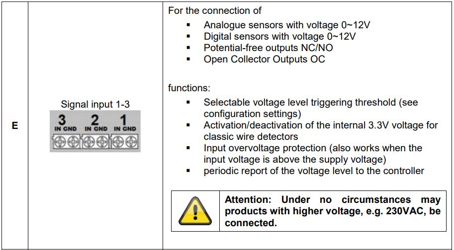
Installation/Wiring![]() The maximum voltage of the devices to be connected is 12 volts for the inputs and 24 volts for the outputs. Attention: Under no circumstances may products with higher voltage, such as 230VAC, be connected.
The maximum voltage of the devices to be connected is 12 volts for the inputs and 24 volts for the outputs. Attention: Under no circumstances may products with higher voltage, such as 230VAC, be connected.
Notes on the disposal of the device![]() Attention: The EU Directive 2012/19/EU regulates the proper return, treatment and recycling of used electronic equipment. This symbol means that, in the interest of environmental protection, the device must be disposed of at the end of its service life in accordance with the applicable legal regulations and separately from household or commercial waste. The old device can be disposed of at the appropriate official collection points in your country. Observe local regulations when disposing of the materials. For further details about the take-back (also for non-EU countries), please contact your local administration. Separate collection and recycling helps to conserve natural resources and ensures that all regulations for the protection of health and the environment are observed when recycling the product.
Attention: The EU Directive 2012/19/EU regulates the proper return, treatment and recycling of used electronic equipment. This symbol means that, in the interest of environmental protection, the device must be disposed of at the end of its service life in accordance with the applicable legal regulations and separately from household or commercial waste. The old device can be disposed of at the appropriate official collection points in your country. Observe local regulations when disposing of the materials. For further details about the take-back (also for non-EU countries), please contact your local administration. Separate collection and recycling helps to conserve natural resources and ensures that all regulations for the protection of health and the environment are observed when recycling the product.
1. Product launch
1.1. Scope of delivery
- Nexello 3I/3O Hybrid Module
- Mounting material: screws and dowels
- Quick guide & safety instructions
- DSK card
1.2. Device features

1.3. Operating principle
The PLHA10100 was developed for use in alarm and home automation systems that use the Z-Wave wireless standard. The device has the following functions:
- Integration of wired sensors and actuators into the Z-Wave wireless protocol
- Three signal inputs
- Three relay outputs
- Emergency power supply and sabotage protection
1.4. Performance features
The device..:
- … is Z-Wave Plus compatible & certified
- …supports the Z-Wave S2 standard (Security 2)
1.5. Use in systems of different manufacturers
Communication is via the Z-Wave EU frequency (868.4 MHz). You can integrate the device into any Z-Wave network with a certified Z-Wave controller, regardless of the manufacturer. All non-battery powered nodes in the network act as amplifiers to amplify the wireless communication of the network.
1.6. DSK code
The DSK code (Device-Specific-Key) is the device-specific key of your device and is required for secure teach-in (inclusion) via S2 on the Z-Wave controller. The first 5 digits of the DSK Code can be found under the QR Code on the back of the product. Please enter them in the inclusion process when prompted. Alternatively, you can transfer the entire DSK code that you find on the enclosed DSK card to the Z-Wave controller via QR Code Scan. Please keep the DSK card in a safe place!
Hint: We recommend secure S2 inclusion (must be supported by the Z-Wave controller) Please enter the 5 digits of the DSK code (bottom of the device) or the entire DSK code (QR code) when prompted.
2. Functional overview
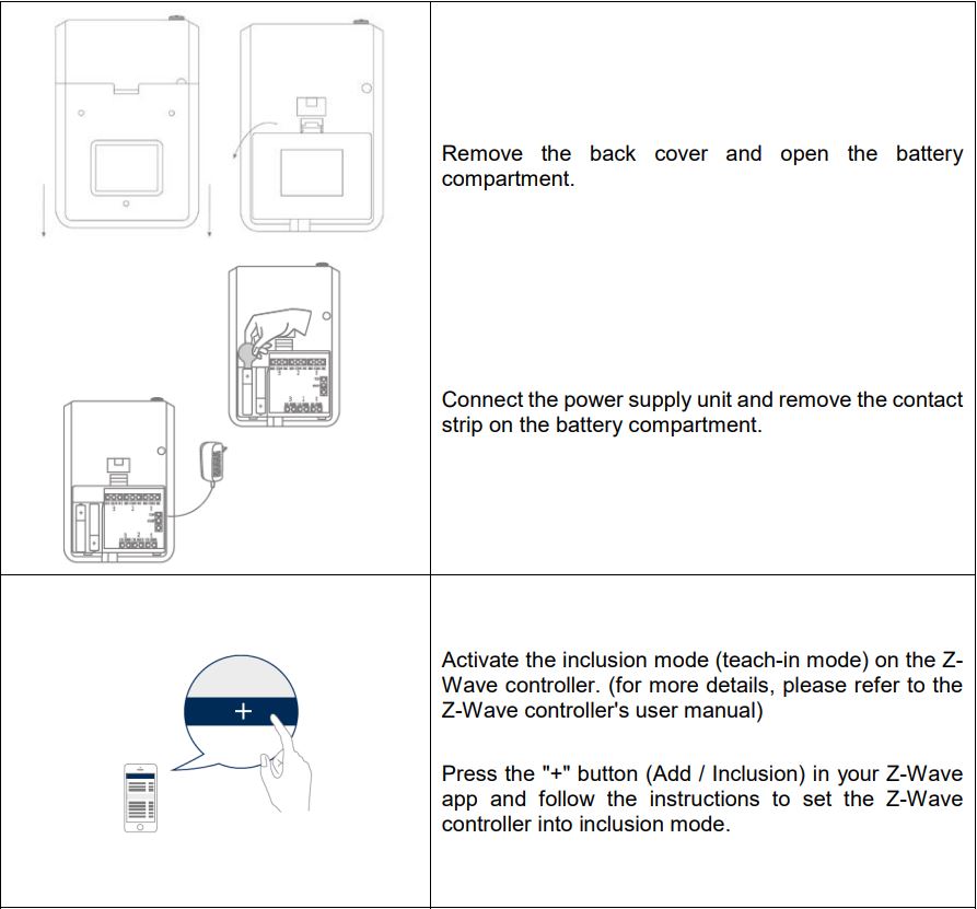
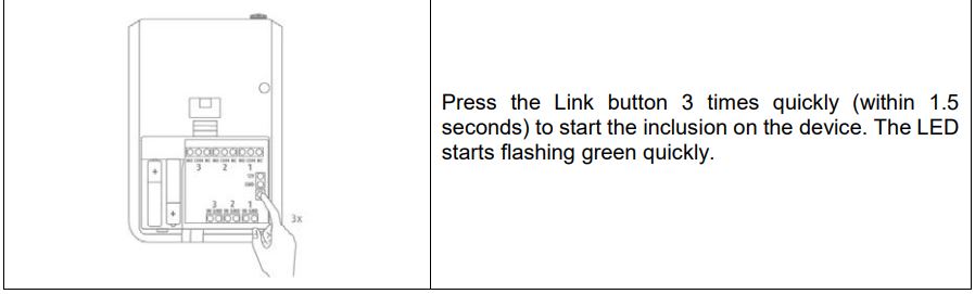
2.1. Inclusion / Teach-in device
This product supports Smart Start:Smart Start-enabled products can be added to a Z-Wave network by scanning the Z-Wave QR code present on the product with a controller that provides Smart Start integration. No further action is required, and the Smart Start product will be automatically added near the network within 10 minutes of power-up.
2.2. Planning, assembly and installation
- The device uses low power radio signals to communicate with the Z-Wave controller. For best results, please note the following:
- The device has a radio range of up to 40 m.
- Due to its design, the device is only suitable for surface mounting indoors.
Example installation:

Please observe the safety instructions:
 The maximum voltage of the devices to be connected is 12 volts for the inputs and 24 volts for the outputs.
- Attention: Under no circumstances may products with higher voltage, such as 230VAC, be connected.
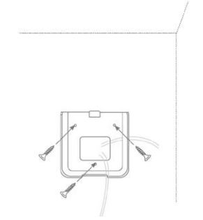
Screw the bracket to the wall. Variant 1: Ideally, use a flush-mounted box as storage space for the cables. The holder has a corresponding opening and the battery compartment has a predetermined breaking point, which you can open carefully with a cutter knife, for example. This allows the cables to be inserted into the product from behind. Variant 2:

Alternatively, the cables can also be surface-mounted and inserted from below. 1 2
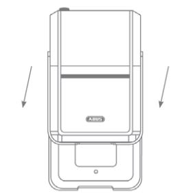
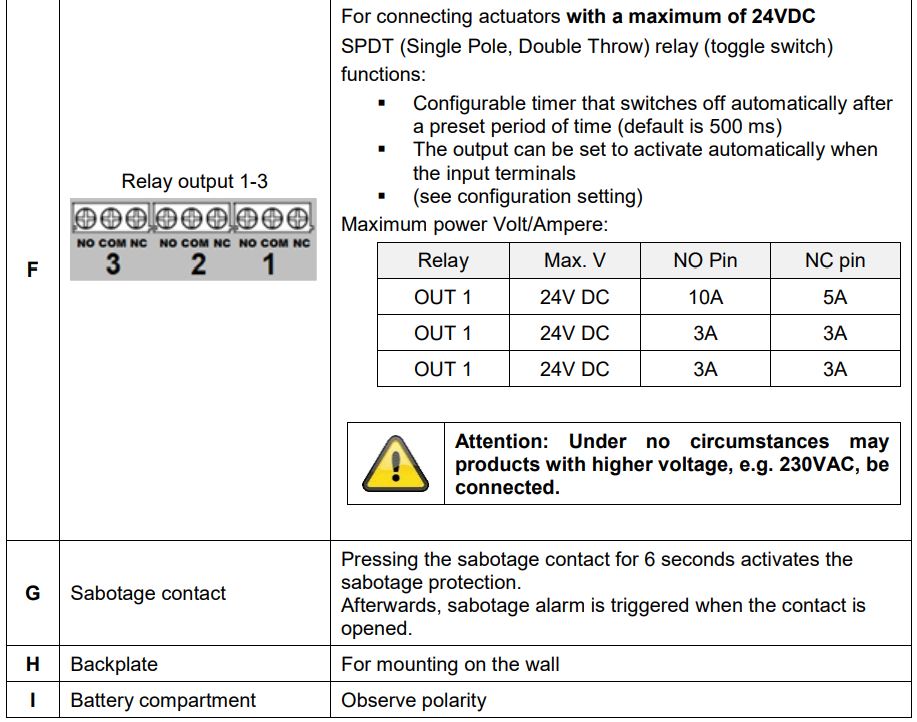
Wire the devices to be connected in accordance with the instructions in Chapter 1.2. and the safety instructions. Use the integrated train protection. Leave enough clearance for the cables during wiring to still be able to remove the device from the wall. Then place the device on the wall bracket, the tamper protection is activated automatically after 6 seconds.
2.3. Exclusion / teach-in device
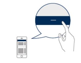
Activate the exclusion mode (learn mode) on the Z-Wave controller. (for more details, please refer to the Z-Wave controller’s user manual)Or press the “-” button (Remove / Exclusion) in your Z-Wave app and follow the instructions to set the Z-Wave controller to Exclusion mode.

Press the Link button 3 times quickly (within 1.5 seconds) to start the exclusion on the device.
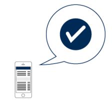
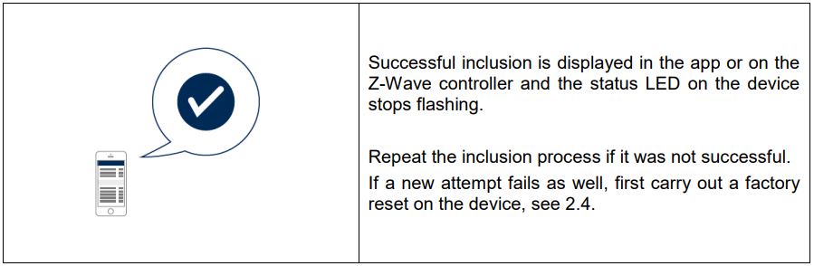
The successful exclusion is displayed in the app or on the Z-Wave controller
2.4. Reset to factory settings
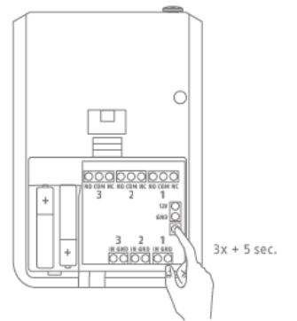
Press the Link button 3 times quickly (within 1.5 seconds). Press quickly (within 1 second) a fourth time and press and hold the Link button for at least 5 seconds. The device is now reset to factory settings.
Hint:This procedure should only be used if the primary network controller is not capable of acting. If the device is set to factory default, the status is set to “not included” and the association settings and possible configurations are reset to default.
3. Advanced Z-Wave Parameters
3.1. Association Groups
Z-Wave devices can control other devices directly. This direct control is called association in Z-Wave. The device ID of the device to be controlled must be stored in the controlling devices. This is done in so-called association groups. An association group is always linked to an event in the controlling device (keystroke or triggering of a sensor). When this event occurs, a control command – usually a BASIC SET – is sent to all devices stored in an association group.
The device supports the following association groups:
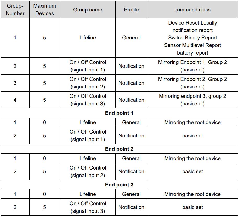
Group 1 (the Z-Wave controller)
- The Lifeline Association is automatically established between the Z-Wave controller and the device at inclusion and defines what information is exchanged between the Z-Wave controller and the device.
Group 2, 3 and 4 (direct association with up to 5 terminals)
- When a signal input (IN 1-3) is triggered, the unit first sends a BASIC Set ON. When the preset timer expires, it sends a BASIC Set OFF.
Multi Channel Root map (Association Group Information)
Sensor Multilevel Command Class — End point 1Switch Binary Command Class — End point 4Basic Command Class — End point 4
3.2. Wake Up Time
The device is an Always On Slave and therefore does not require a Wake Up function. The device can be controlled by the Z-Wave controller at any time.
3.3. Reports
notification report
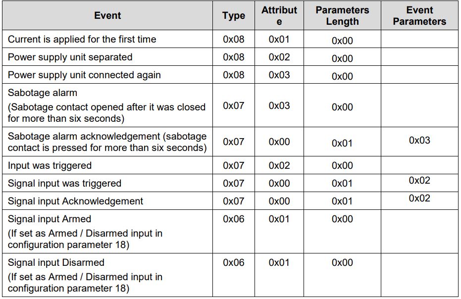
battery reportBattery message for the backup battery

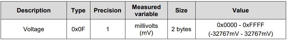
Sensor Multilevel reportReport about voltage in millivolts at the 3 signal inputs
Switch Binary reportSends report when relay outputs 1-3 are switched on or off.

(There is a delay of 2 seconds for the automatic shutdown after the shutdown is completed. )
Device Reset Locally ReportA “Device Reset Locally” report is sent when the device is reset to factory settings.
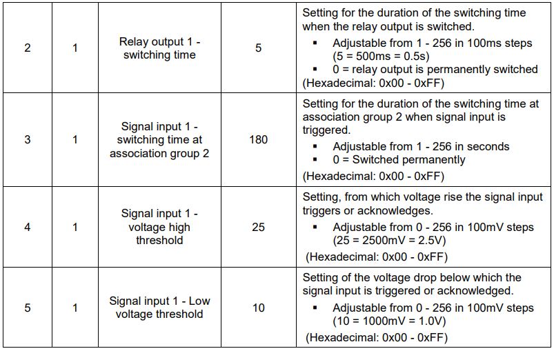
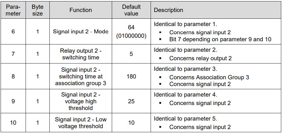
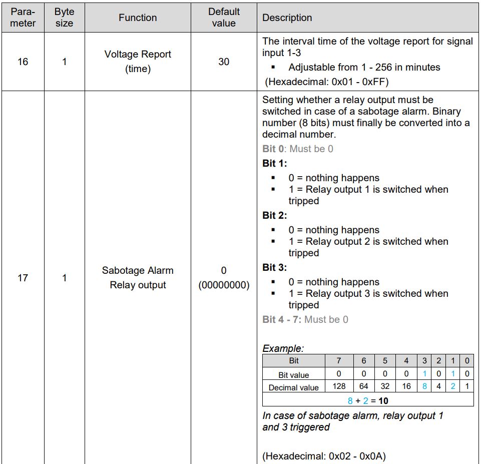
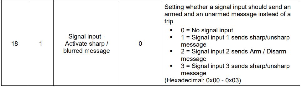
3.4. Overview Configuration Parameters
Z-Wave products can be used directly after inclusion in the network. However, configuration settings can be used to adapt the behavior of the device even better to the requirements of the application and to activate additional functions.
For signal input 1 and relay output 1

For signal input 3 and relay output 3
For signal input 3 and relay output 3

General settings
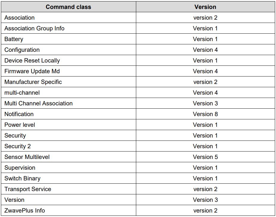
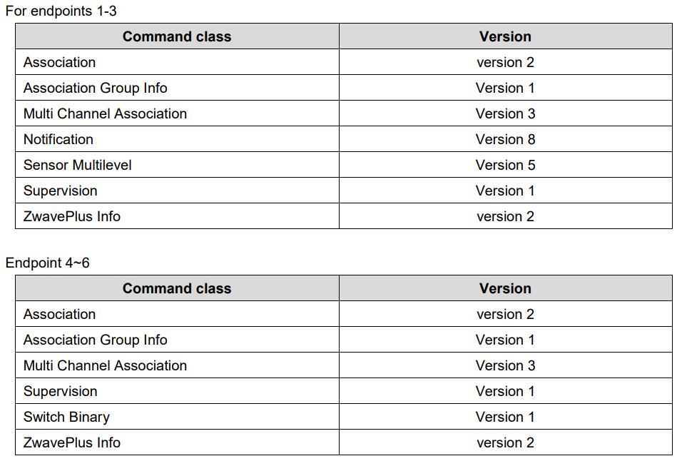
3.5. Supported command classes
3.6. Supported security levels
- Security S2 Authenticated
- Security S2 Unauthenticated
- Security S0 Authenticated
3.7. Description of the endpoints

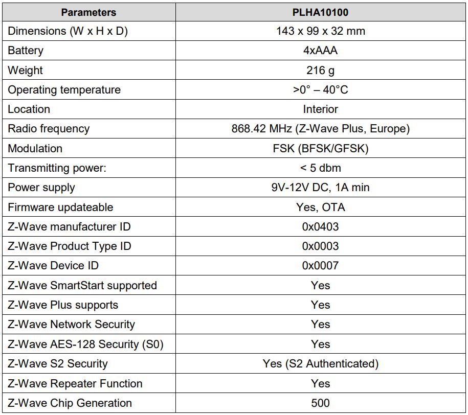
4. Technical data
References
[xyz-ips snippet=”download-snippet”]