
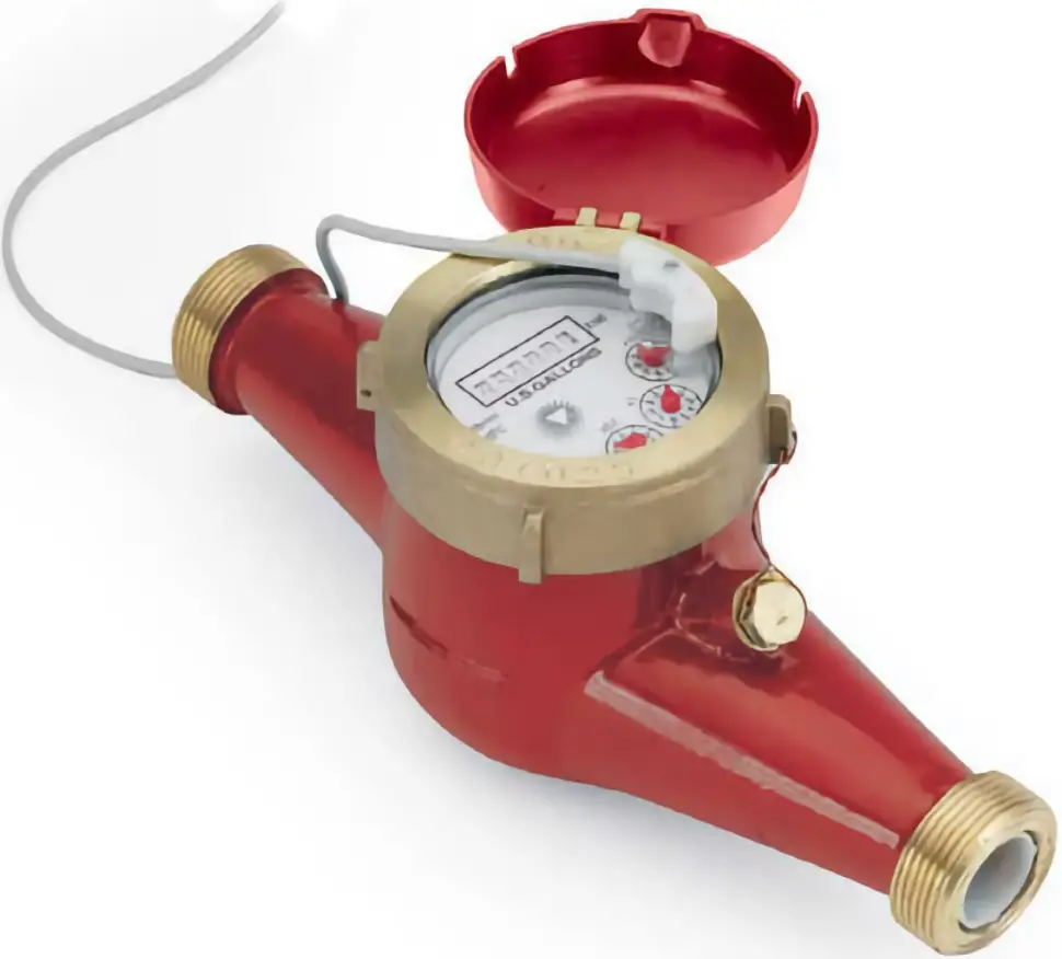
AccentPDIR ACS-H-075-R Hot Water Meters with Contact Output
Main Technical Data
|
Nominal Diameter |
DN | 075 – 3/4 | 10 – 1” | 150 – 1 ½” | 200 – 2” | |
| Maximum Flow Rate | US gpm | Qmax | 22 | 30.8 | 88 |
132 |
|
Nominal Flow Rate |
US gpm | Qn | 11 | 15.4 | 44 | 66 |
| Transition Flow Rate | US gpm | Qt | 0.88 | 1.23 | 3.52 |
5.3 |
|
Minimum Flow Rate |
US gpm | Qmin | 0.22 | 0.31 | 0.88 | 1.32 |
| Minimum Reading | US Gallon | 0.01 | 0.01 | 0.1 |
0.1 |
|
|
Minimum Graduation |
US Gallon | 0.005 | 0.005 | 0.05 |
0.05 |
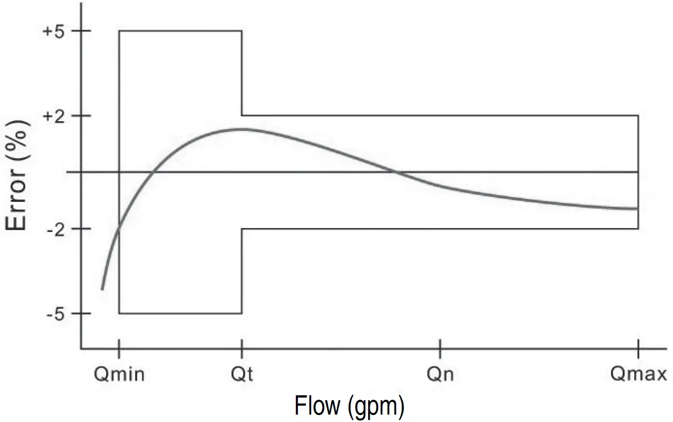
Maximum Permissible Error
In the lower zone from Qmin inclusive up to but excluding Qt is ±5%.In the upper zone from Qt inclusive up to and including Qmax is ±2%.
Accuracy Curve
Specifications
| Temperature | 194°F (90°C) max | |
| Pressure | 150 psi operating | |
| Materials | Body | Cast bronze |
| Internals | Engineered thermoplastic | |
| Magnet | Alnico | |
| Accuracy | +/- 1.5% of reading | |
| Sensor | Reed switch | |
| Maximum Current | 20 mA | |
| Maximum Voltage | 24 Vdc or Vac | |
| Cable Length | 12′(4m) std (2000′ max run) |
General Information
ACS Series meters use the internationally-acceptedmulti-jet principle. A gear train drives the register totalizer dials. For pulse output, one of the pointers is replaced by a magnet arm, which is detected by a reed switch sensor attached to the outside of the lens. The reed switch provides dry contact closure and does not require power.
Pulse Output
Reed switch sensors respond to a magnet that rotates on the face of the meter under the lens. The sensor turns on and off once each time the magnet passes under it. Sensors are designed for electronic control loads, and should not be used to switch power loads or line voltages. See maximum current and voltage ratings, under specifications.
Inlet Strainer
Clean the strainer yearly, or as required, depending on water condition. Pull out the strainer or back-flush the meter to loosen trapped particulates.
Calibration
New meters are factory tested to meet AWWA C-708Multi-Jet Meter accuracy specification.
Suggested Meter Installation
- Thoroughly flush the service line upstream of the meter to remove dirt and debris.
- Set the meter inline. Water meters are recommended to be installed horizontally with the register facing upwards.
- Make sure the water flow follows the arrow cast on the meter body.
- Slowly open any upstream valves to prevent damage to the meter.
Connection Diagrams
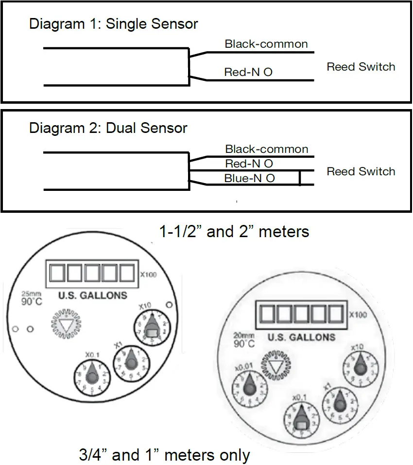
Changing Pulse Rates
The pulse rate is determined by the dial on which the magnet pointer is located. To move the magnet pointer, remove meter top and lens, taking care not to lose the sealing ring. With fingers, lift the magnet pointer off its shaft and remove the plain pointer from the target dial. Reverse their positions and press them firmly into place. Securely seat the sealing ring and then replace the lens, matching the tab on the lens to the notch on the meter so as to align the sensor with the magnetic pointer dial. Thread the meter top on and tighten.
Warranty
ACS water meters are warranted to perform to AWWA new meter accuracy standards, and to be free from defects in materials and workmanship for a period of 12 months from date of shipment. If a meter does not perform as warranted, AccentPDIR will repair it free of charge subject to the terms of this warranty.AccentPDIR liability under this performance warranty is expressly limited to the repair or replacement of the meter upon the customer’s returning the complete meter prepaid to:
AccentPDIRRepair Department2564 Industry LaneNorristown, PA 19403
This performance guarantee shall not be applicable to meters which have been damaged by aggressive water conditions, foreign matter in media, mis-application, willful misconduct, negligence, vandalism, act of God, improper installation, frost/freeze damage or using the meter outside of it’s specific operating parameters (especially temperature and flow ranges).In no event shall AccentPDIR be liable for incidental or consequential damages of any kind, including but not limited to loss of profits or revenue, loss of use, cost of capital, cost of substitute equipment, facilities or services, downtime costs, delays and claims of customers of the customer or other third parties.
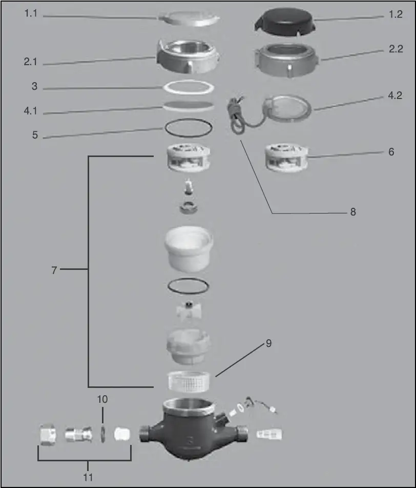
Internal Parts Replacement
All the internal parts of the meter lift out as a unit, after the top has been unscrewed. The lens can then be removed and the internal assembly lifted out. If necessary, turn the meter upside down and tap one end lightly on a countertop to loosen the internals. The assembly can be separated by hand.
![]()
References
[xyz-ips snippet=”download-snippet”]