ACCURITE Professional Wireless
Weather Station User Manual

Thank You for purchasing this ACURITE® Weather Station. Please read this manual in it’s entirety to fully enjoy the benefits and features of this product. Please keep this manual for future reference.
NOTE: A clear film is applied to the LCD at the factory that must be removed prior to using this product. Locate the clear tab and simply peel to remove.
SECTION 1 · OVERVIEW OF FEATURES
About The Menu
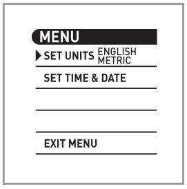
This weather station features a menu that allows you to access basic and advanced features. Press the “MENU” button to enter into MENU. Use the UP and DOWN arrow buttons to scroll through the options. Press the “OK” button to enter into a selected option in the menu. The display will prompt you for further action. It is recommended that you explore sections 4 and 5 to learn more about the menu options.
SECTION 2 · SETUP
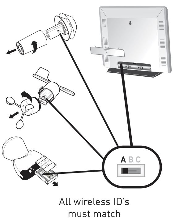
A/B/C Wireless SelectionTo allow for more than one weather station and wireless sensor network to be used in close proximity, the main unit and all 3 wireless sensors have a small switch labeled “A B C” near or in the battery compartments. These switches are all factory preset into the same position (either A, B, or C). This switch selects one of 3 wireless modes to use, and all 4 switches in all 4 components MUST be set in matching positions (either A, B, or C) for wireless communication to take place successfully.
Install Batteries
Batteries must be installed into all three of the wireless sensors BEFORE installing batteries into the main display unit. Use only fresh or new batteries in all cases, and install correctly according to the polarity ( – & + ) symbols marked on the batteries and in the battery compartments. We suggest using lithium batteries for better cold weather performance. Do not mix old and new batteries.
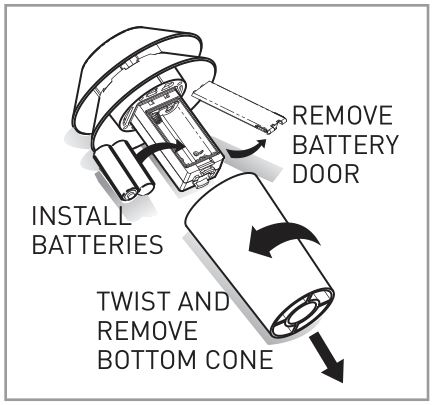
Wireless Temperature & Humidity Sensor INSTALL BATTERIES:
1. Twist and remove larger bottom cone section.2. Remove the battery door and set aside.3. Install 2 “AA” batteries into the battery compartment.4. Replace the battery door and replace and twist the bottom cone section.
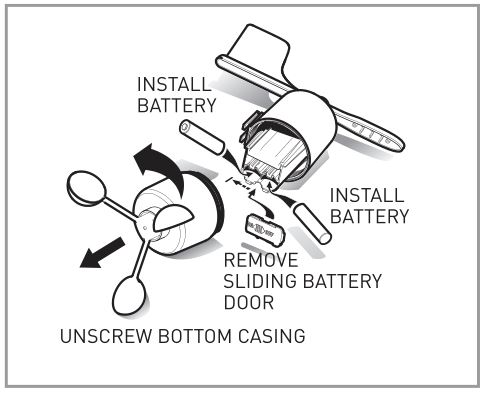
Wireless Wind Sensor INSTALL BATTERIES:
1. Unscrew and remove bottom case section.2. Remove the battery door and set aside.3. Install 2 “AA” batteries into the battery compartment.4. Replace the battery door and replace and rotate the bottom cone section until it is securely tightened.
Wireless Rain Collector INSTALL BATTERIES:
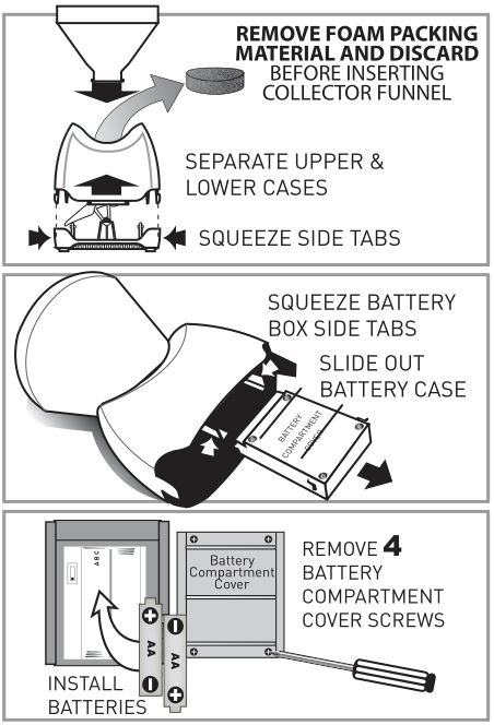
1. Squeeze side tabs and separate upper and lower cases.2. Squeeze battery box side tabs and slide out the battery box.3. Install 2 “AA” batteries into the battery compartment by removing 4 screws.4. Slide the battery box back into the case, aligning the slide rails and tabs correctly. The battery compartment cover should be facing outwards.
Main Unit INSTALL BATTERIES:1. Remove the bottom display stand by pulling firmly.2. Remove the battery door and set aside.3. Install 3 “AA” batteries into the battery compartment.4. Replace the battery door and replace and rotate the bottom cone section until it is securely tightened.
AND/OR
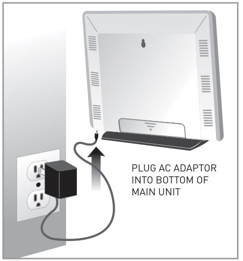
PLUG IN AC POWER ADAPTOR1. Plug AC adaptor into the bottom of the main unit.2. Plug AC adaptor into a 110v AC wall outlet.
NOTE: Main unit will run on AC power adaptor until unplugged or a power outage occurs. If you also have “AA” batteries installed, the unit will continue to operate when unplugged or during a power outage.
Main Unit Basic Setup
After batteries are installed in all 3 wireless sensors and the main unit is powered up (with batteries and/or AC adaptor), the main unit will automatically prompt you to set your unit preference and the initial time and date. After the atomic clock signal is received, the time and date will be maintained automatically. If you choose not set any preferences initially, the main unit will use the defaults and begin searching for the atomic clock signal to set itself. This may take up to 24 hours and may not occur at all depending on your geographical location and your physical surroundings. See “troubleshooting” for atomic clock tips.
SET UNITS (ºF/ºC):1. Press the “OK” button to enter into unit selection.2. Press the UP or DOWN button to select either “ENGLISH” (ºF, mph, inches) or “METRIC” (ºC, kph, mm). Press “OK” again to confirm your selection.
SET TIME & DATE:
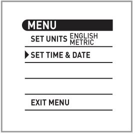
- Press the “OK” button to enter into time & date setting mode.
- SET TIMEZONE- Press the UP and DOWN buttons to select your timezone, or cycle through all of the timezones and into GMT (greenwich mean time) world time zone setting. Press the “OK” button to confirm your setting and move on.
- SET DAYLIGHT SAVING TIME (DST)”DST” will appear on the lower display. Press the UP and DOWN buttons to select “ON” or “OFF” for DST. Press the “OK” button to confirm your setting and move on.
- SET CLOCK- Press the UP and DOWN buttons to adjust the HOUR (note the AM and PM indicators) and then press the “OK” button to move on to setting the MINUTES. Press the UP and DOWN buttons again to adjust the MINUTES. Press the “OK” button to confirm your setting and move on.
- SET THE YEAR- Press the “UP” button to adjust the YEAR. Press the “OK” button to confirm your setting and move on.
- SET THE MONTH- Press the UP and DOWN buttons to adjust the MONTH. Press the “OK” button to confirm your setting and move on.
- SET DATE- Press the UP and DOWN buttons to adjust the DATE. Press the “OK” button to confirm your setting and move on.
Your initial time and date setting is complete. You may now exit the menu and continue with normal weather station operation.
The main unit will start to search for the 3 wireless sensors, and will also search for the atomic clock signal. When the main unit picks up the atomic clock signal, the time and date will automatically be maintained with split second accuracy. See section 6 in the back of this manual for more information about the atomic clock.
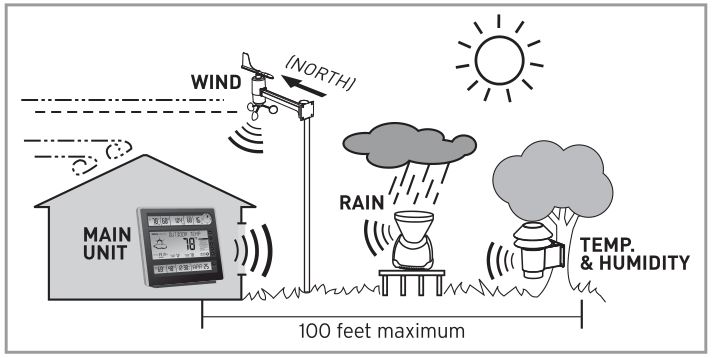
SECTION 3 · PLACEMENT
Now that setup is complete, you must choose a location to place the 3 wireless sensors and the main unit. The wireless sensors MUST be placed LESS THAN 100 feet away from the main unit.
This wireless weather station uses radio frequency for communication, which is susceptible to interference from other electronic devices and large metallic items or thick walls. Always place both units at least 3 feet away from appliances ( TV, microwave, radios, etc. ) or objects ( large metal surfaces, thick stone walls, etc. ) that may interfere with the wireless communication.
Placement of Main Unit
 Place the main unit in a dry area free of dirt and dust. To help ensure an accurate indoor temperature measurement, be sure to place the main unit out of direct sunlight, and away from any heat sources or vents in your home.
There are 2 placement options for the main unit. You may hang the main unit on a wall using the integrated hang hole on the back. Alternatively, you may place the main unit on a table top or other flat surface utilizing the removable Main Unit display stand.
Placement of Sensors
 The wireless sensors MUST BE PLACED OUTDOORS to observe outdoor weather conditions and relay them to the main unit display. The wireless sensors must be placed less than 100 feet from the main unit.
Wireless Temperature & Humidity Sensor PLACEMENT
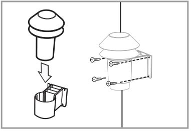
1. Attach the temperature & humidity sensor to the mounting bracket by simply sliding into the bracket.2. Attach to a solid vertical surface out of direct sunlight for maximum performance. Attach the mounting bracket utilizing the included screws and wall anchors (if applicable). Depending on the mounting surface, other steps may need to take place to ensure the sensor is mounted successfully.
Alternatively, the wireless temperature sensor may be mounted onto a PVC pole. See “Alternative Mounting Option” later in this section.
Wireless Wind Sensor PLACEMENT

1. Attach the wind sensor to the mounting bracket by simply sliding into the bracket.
2. The sensor must be mounted with the bracket pointing NORTH as indicated on the bracket and on the top surface of the wind sensor itself. The wireless wind sensor should be mounted high above all potential wind obstructions for maximum performance, keeping in mind it must remain within the 100 ft. wireless range of the main display unit.
Attach to a solid surface utilizing the included screws and wall anchors (if applicable). Depending on the mounting surface, other steps may need to take place to ensure the sensor is mounted successfully.
Alternatively, the wireless wind sensor may be mounted onto a PVC pole. See “Alternative Mounting Option” later in this section.
Wireless Rain Collector PLACEMENT
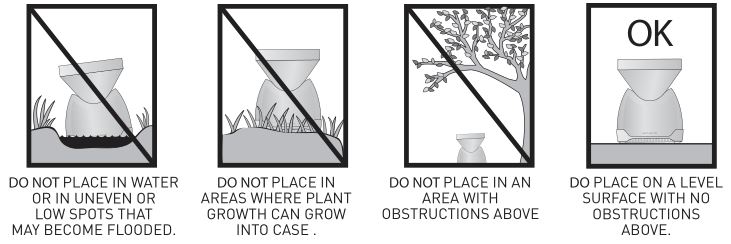
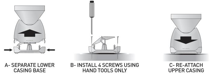
1. The wireless rain collector MUST be placed on a flat, level surface to allow for proper rain measurement. Make certain the rain collector is not placed in a low spot that may become flooded or in an are where there are obstructions above it such as trees or other structures that may block the rain from being collected properly.
It is strongly recommended that the rain collector be mounted to a solid, flat surface such as a deck railing for best results. Depending on the mounting surface, other steps may need to take place to ensure the sensor is mounted successfully.
2. To mount the rain collector, first separate the lower casing base from the upper casing. Next locate the four holes within the lower casing base. Then, using only hand tools (power tools may slip during use, possibly damaging sensitive rain collector components), secure the lower casing base to the chosen surface using the appropriate hardware.
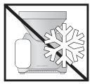 The Wireless Rain Collector is designed to collect and record liquid rainfall only, it will not detect or record snowfall levels. It is recommended that the rain collector be brought indoors if you live in an area that has extreme cold weather, ice and snow during the winter months.
Alternative Mounting Option
WIRELESS TEMPERATURE/HUMIDITY & WIND SENSORS

Both sensors are designed to mount onto a pole structure (not included). We recommend using plastic pipe to reduce the likelihood of lightening strikes metal poles would be subject to.
Use a 3cm (outer diameter) PVC or plastic pipe to fashion a mast to bring sensors high above obstructions. Mount the temperature & humidity sensor directly and the wind sensor bracket arm. Check the main unit display to make sure you have a good wireless connection before permanently mounting the sensors and the pole/mast.
SECTION 4 · OPERATION

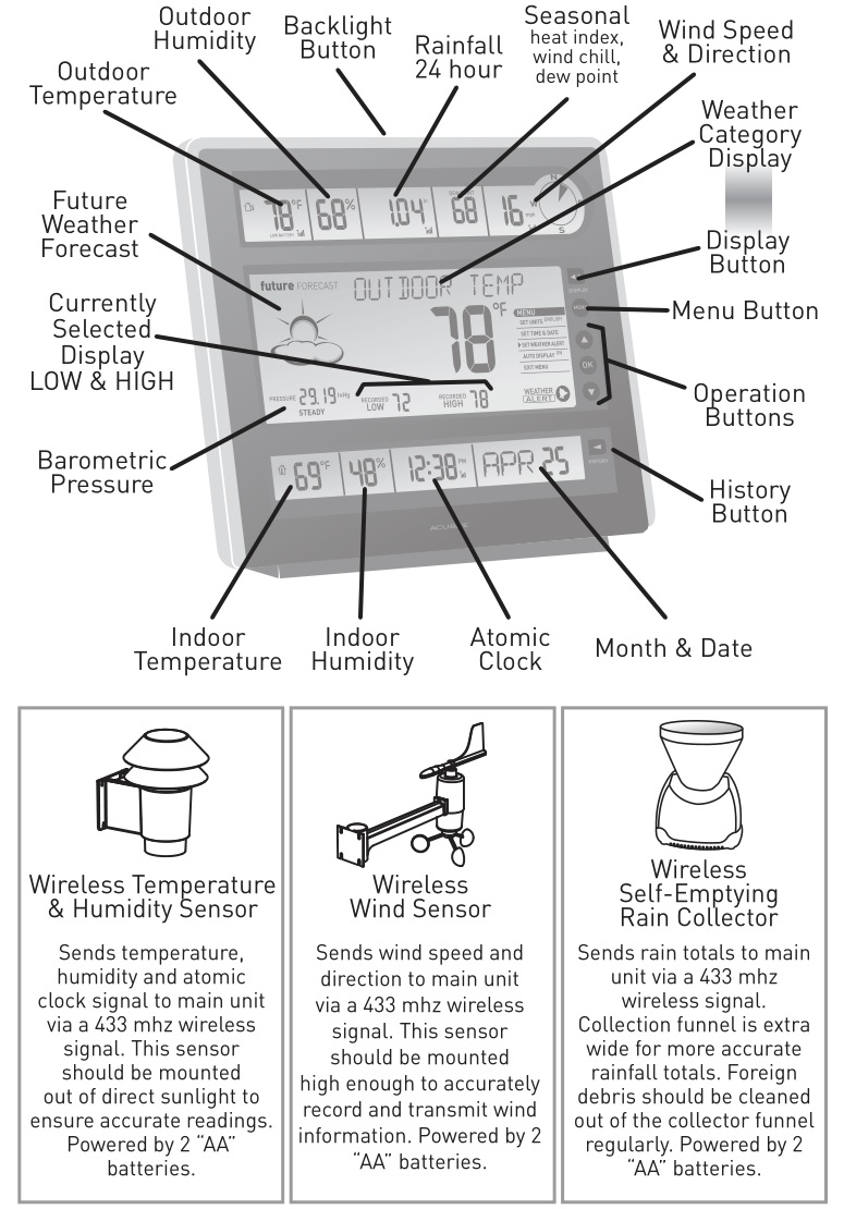
A. WEATHER CATEGORY DISPLAYThe “DISPLAY” button cycles through weather information available and shows it in the large display for easy viewing. The following weather information categories are available to display in this area:
OUTDOOR TEMPERATURE, OUTDOOR HUMIDITY, RAINFALL, WIND SPEED, BAROMETRIC PRESSURE, INDOOR TEMPERATURE, INDOOR HUMIDITY
Note that the recorded low and high are shown below the currently displayed weather category. While each weather category is selected and displayed in the large display area, there is more information displayed and other options that can be set.
B. HISTORY: CURRENTLY SELECTED WEATHERAlso available to you is the option to go back through 7 days of history for the currently displayed weather category. Simply press the “HISTORY” button repeatedly to go back 1 day per button press, up to seven days. Exit out of history mode by pressing the “HISTORY” button an eighth time or allow the display to exit automatically after 15 seconds of inactivity. To view the history of another weather category, press the “DISPLAY” button to change the weather category. Then press the “HISTORY” button to view the history of the currently displayed weather category.
C. WEATHER FORECAST: ICONSThis feature gives you the predicted weather forecast for the next 12 to 24 hours based on an advanced algorithm that includes barometric pressure system and temperature tracking. This weather station will provide the most accurate forecast that a single station weather instrument can provide.
D. WEATHER FORECAST: 14 DAY LEARNING MODEThis weather station has a patent pending fourteen day learning mode calibration process. During this learning mode the weather station will make altitude calculations that may affect the accuracy of the forecast. Once the 14 day learning mode process is complete, the learning mode icon will disappear and the weather forecast should be ready for superior operation. You can track the progress of the learning mode by viewing the progress bar located just above the future forecast weather icon display area.
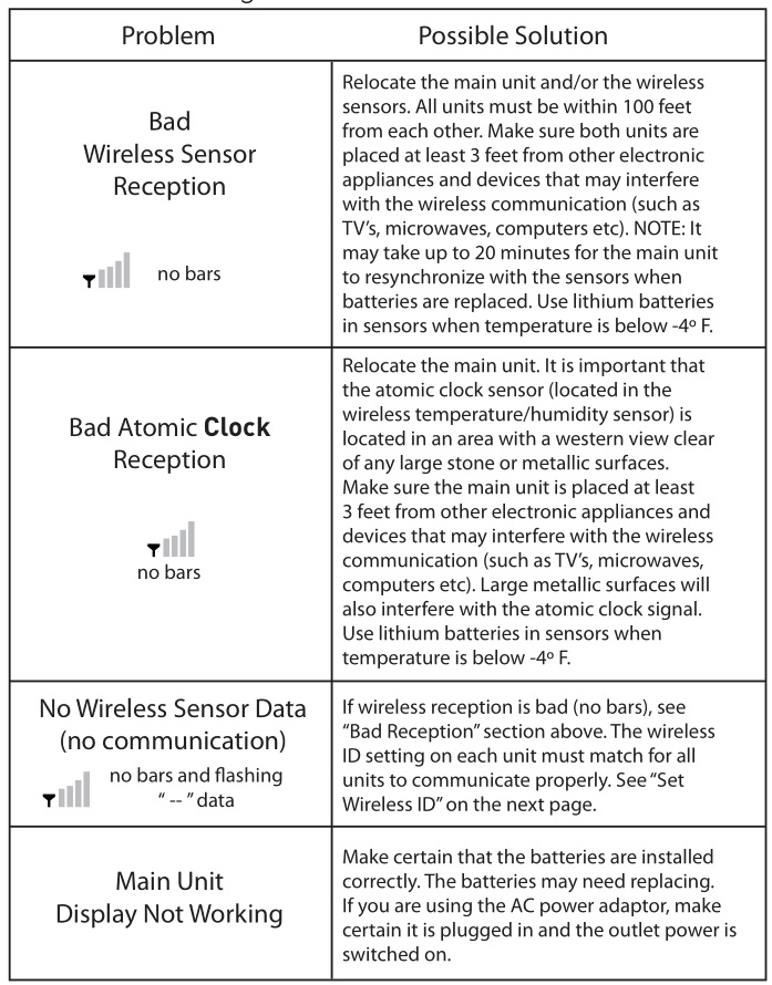
E. WIRELESS SIGNAL: RECEPTION ICONSThe main unit has signal reception icons in the outdoor sensor display areas and near the atomic clock display. If there are a low number of “bars” present, you may experience no temperature display ( “–” ) or inaccuracy. See the troubleshooting section for more tips on wireless signal reception for the sensors and for the atomic clock signal.
SECTION 5 · ADVANCED FEATURES
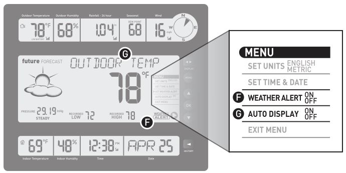
F. ADVANCED FEATURES: WEATHER ALERTAvailable to you is the option to set LOW and HIGH alerts for some of the displayed weather categories. You may set and turn the alert ON or OFF separately for each of the displayed weather categories. For example, lets say you have set the alert to be ON for outdoor temperature. If the current outdoor temperature falls BELOW the LOW alert value or raises ABOVE the HIGH alert value, you will be notified with an audible alarm and a “WEATHER ALERT” icon on the display. Press any button to silence the audio alarm. The “Weather Alert” icon will continue to be present as long as conditions remain at alert levels or until the “Weather Alert” is turned off for that weather category.
WEATHER ALERT ON/SET: To set a weather alert for a weather category, first select the desired weather category using the “DISPLAY” button. Press the “MENU” button and use the DOWN button to scroll down to “WEATHER ALERT” selection. Press the “OK” button. Press the UP or DOWN buttons to select “ON.”
SET WEATHER ALERT LOW: You will then be prompted to SET a LOW alert value. If the reading for the currently displayed weather category falls below the set value, the WEATHER ALERT icon will display and the weather station will sound an audio alarm. Press the UP or DOWN buttons to adjust the weather alert LOW setting. Press the “OK” button to confirm your setting and move on to setting the HIGH alert value.
SET WEATHER ALERT HIGH: Now you will be prompted to SET a HIGH alert value. If the reading for the currently displayed weather category rises above the set value, the WEATHER ALERT icon will display and the weather station will sound an audio alarm. Press the UP or DOWN buttons to adjust the weather alert HIGH setting. Press the “OK” button to confirm your setting and exit WEATHER ALERT set mode and return to menu.
WEATHER ALERT OFF: To turn OFF weather alerts for a weather category, select WEATHER ALERT in menu and then select “OFF” when in the category you wish to deactivate weather alerts in.
ABOUT THE MENUThis weather station features a menu that allows you to access basic and advanced features. Press the “MENU” button to enter into MENU. Use the UP and DOWN arrow buttons to scroll through the options. Press the “OK” button to enter into a selected option in the menu. The display will prompt you for further action.
After you are finished adjusting or setting options, you will be right back in the menu in most cases. If there is no activity for a period of time, you will automatically exit out of the menu and back into normal weather station operation. Alternatively you may just scroll down to “EXIT MENU” and push the “OK” button to exit.
G. ADVANCED FEATURES: AUTO DISPLAYAlso available to you is the option to have the weather station automatically display the weather category or categories that are currently out of normal weather range.
This feature uses an internal memory of normal weather ranges for temperature, rain, wind and seasonal values (wind chill / dew point / heat index). If any of the weather categories current readings fall below or raise above the factory set extremes, the auto display will take over. The currently displayed weather category will then automatically switch to the affected weather category. This will only happen if the “WEATHER ALERT” feature is turned ON.
NOTE: It is important that all of the sensors be placed in a manner that will allow for the most accurate weather condition data to be transmitted to the main unit. For example, it will be problematic if the WIRELESS TEMPERATURE & HUMIDITY sensor is near an external heat source, or is absorbing too much direct or reflected sunlight at certain times of the day. This will cause artificially high extreme temperatures, which will cause the outdoor temperature category to automatically display.
AUTO DISPLAY ON: To turn the auto display feature on, press the “MENU” button and use the DOWN button to scroll down to “AUTO DISPLAY” selection. Press the “OK” button. Press the UP or DOWN buttons to select “ON.”
AUTO DISPLAY OFF: To turn the auto display feature off, press the “MENU” button and use the DOWN button to scroll down to “AUTO DISPLAY” selection. Press the “OK” button. Press the UP or DOWN buttons to select “OFF.”
SECTION 6 · TROUBLESHOOTING and INFORMATION
Troubleshooting
Operating Range of Batteries
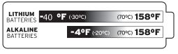 Extended periods of cold temperatures ( below -4ºF / -20ºC ) can cause alkaline batteries to function improperly. This will cause the outdoor wireless sensor to stop transmitting temperature readings. Use lithium batteries in these low temperature conditions to ensure continued operation for wireless sensors placed outdoors.
Set Wireless ID
This wireless weather station uses long range 433mhz radio frequency for communication.
In the event that you have reception problems due to interference, both the main unit and the 3 wireless sensors have a selectable wireless ID. The ID switches are located within the battery compartments of the main unit and the 3 wireless sensors.
You may choose A, B or C; but both the main units and the wireless sensors IDs must match for successful synchronization.
About the Atomic Clock
A clock is considered atomic if it has an accuracy of one second in a million years. Consumer clocks are considered atomic if they attain this accuracy by receiving a signal from an atomic clock. In North America, the National Institute of Standards and Technologies operates an atomic clock in Colorado which transmits the time codes via the radio station WWVB. The signal is transmitted in a very low frequency (60,000 Hz). The Acurite clock you have purchased includes a built-in receiver which picks up the signal from the WWVB station. NOTE: Due to solar radiation in the atmosphere, the atomic clock signal is weak during the day. Most synchronization with the WWVB atomic clock signal happens at night when there is less interference.
Measurement Ranges
TemperatureMain Unit Temperature: 32ºF to 122ºF / 0ºC to 50ºCWireless Sensors:temperature sensor: -40ºF to 158ºF / -40ºC to 70ºChumidity sensor: 16% RH to 99% RHwind sensor: up to 99 mph / 159 Kph (depending on conditions)rainfall collector sensor: 0 to 99.99 inches / 2539 mm
Specifications
Power RequirementsMain Unit: 3 x “AA” alkaline or lithium batteries or AC power AdaptorWireless Sensors:temperature & humidity sensor: 2 x “AA” alkaline or lithium (recommended) batterieswind sensor: 2 x “AA” alkaline or lithium (recommended) batteriesrainfall collector sensor: 2 x “AA” alkaline or lithium (recommended) batteries
Wireless CommunicationRadio Frequency: 433 mhzTransmission Intervals: every 16 seconds
Atomic ClockFrequency: WWVB 60KhzSynchronizes Daily
SAFETY:DAMAGECAUSEDBY FAILURETO COMPLYWITH THIS INSTRUCTIONMANUAL WILL INVALIDATEANY MANUFACTURERGUARANTEE.THE MANUFACTURER AND SUPPLIERWILL NOT BE HELD LIABLE FORDAMAGESDUETO FAILURETO COMPLYWITH THIS INSTRUCTIONMANUAL OR FROMDATAINACCURACIES THAT MAY OCCURWITH THIS PRODUCT.
IN CASEOF HARM OR DAMAGETO A PERSONOR PROPERTYCAUSEDBY IMPROPERHANDLINGOR FAILURETO COMPLYWITH THIS INSTRUCTION MANUAL, THE MANUFACTURERAND SUPPLIERCANNOT BE HELD LIABLE.
- Inserting batteries in an incorrect polarity will cause damage to this weather station and remote sensors. · Do not dispose of new or used batteries in a fire as they may explode or could release dangerous chemicals.
- Please participate in the preservation of the environment by properly disposing of all discarded batteries in designated disposal receptors.
- Do not subject the main unit or remote sensors to excessive force, shock, dust, temperature or humidity, as these conditions may shorten the life of the main unit and/or remote sensors.
- To operate main unit and remote sensors, use only recommended battery types.
- Altering the main unit or remote sensors in any way is strictly prohibited.
- Do not leave discharged batteries in the device as these may corrode and/or release chemicals that may damage this product.
- This product is not to be used for medical, commercial or public purposes.
- This product is not a toy and should be kept out of reach of children.
ALWAYS USE PROPER TOOLS AND MOUNT/PLACE SENSORS IN AREAS THAT WILL BE SAFE TO YOURSELF AND OTHERS. SEEK PROFESSIONAL ASSISTANCE IN MOUNTING/PLACING THE WIRELESS SENSORS AND FOLLOW YOUR LOCAL LAWS AND REGULATIONS WHEN CHOOSING A MOUNTING/PLACEMENT LOCATION FOR THE WIRELESS SENSORS
 PLEASE DISPOSE OF OLD OR DEFECTIVE BATTERIES IN AN ENVIRONMENTALLY SAFE WAY AND IN ACCORDANCE WITH YOUR LOCAL LAWS AND REGULATIONS. BATTERY SAFETY: Follow the polarity (+/-) diagram in the battery compartment. Promptly remove dead batteries from the device. Dispose of used batteries properly. Only batteries of the same or equivalent type as recommended are to be used. DO NOT incinerate used batteries. DO NOT dispose of batteries in fire, as batteries may explode or leak. DO NOT mix old and new batteries or types of batteries (alkaline/standard). DO NOT use rechargeable batteries. DO NOT recharge non-rechargeable batteries. DO NOT short-circuit the supply terminals.
 Log on to http://www.chaneyinstrument.com/product_reg.htm
Please DO NOT return product to the retail store. For technical assistance and product return information, please call Customer Care: 877-221-1252 Mon. – Fri. 8:00 A.M. to 4:45 P.M. (CST)www.chaneyinstrument.com
LIMITED ONE YEAR WARRANTY
Chaney Instrument Company warrants that all products it manufactures to be of good material and workmanship and to be free of defects if properly installed and operated for a period of one year from date of purchase. REMEDY FOR BREACH OF THIS WARRANTY IS EXPRESSLY LIMITED TO REPAIR OR REPLACEMENT OF DEFECTIVE ITEMS. Any product which, under normal use and service, is proven to breach the warranty contained herein within ONE YEAR from date of sale will, upon examination by Chaney, and at its sole option, be repaired or replaced by Chaney. In all cases, transportation costs and charges for returned goods shall be paid for by the purchaser. Chaney hereby disclaims all responsibility for such transportation costs and charges. This warranty will not be breached, and Chaney will give no credit for products it manufactures which shall have received normal wear and tear, been damaged, tampered, abused, improperly installed, damaged in shipping, or repaired or altered by others than authorized representatives of Chaney.
THE ABOVE-DESCRIBED WARRANTY IS EXPRESSLY IN LIEU OF ALL OTHER WARRANTIES, EXPRESS OR IMPLIED, AND ALL OTHER WARRANTIES ARE HEREBY EXPRESSLY DISCLAIMED, INCLUDING WITHOUT LIMITATION THE IMPLIED WARRANTY OF MERCHANTABILITY AND THE IMPLIED WARRANTY OF FITNESS FOR A PARTICULAR PURPOSE. CHANEY EXPRESSLY DISCLAIMS ALL LIABILITY FOR SPECIAL, CONSEQUENTIAL OR INCIDENTAL DAMAGES, WHETHER ARISING IN TORT OR BY CONTRACT FROM ANY BREACH OF THIS WARRANTY. SOME STATES DO NOT ALLOW THE EXCLUSION OR LIMITATION OF INCIDENTAL OR CONSEQUENTIAL DAMAGES, SO THE ABOVE LIMITATION OR EXCLUSION MAY NOT APPLY TO YOU. CHANEY FURTHER DISCLAIMS ALL LIABILITY FROM PERSONAL INJURY RELATING TO ITS PRODUCTS TO THE EXTENT PERMITTED BY LAW. BY ACCEPTANCE OF ANY OF CHANEY’S EQUIPMENT OR PRODUCTS, THE PURCHASER ASSUMES ALL LIABILITY FOR THE CONSEQUENCES ARISING FROM THEIR USE OR MISUSE. NO PERSON, FIRM OR CORPORATION IS AUTHORIZED TO ASSUME FOR CHANEY ANY OTHER LIABILITY IN CONNECTION WITH THE SALE OF ITS PRODUCTS. FURTHERMORE, NO PERSON, FIRM OR CORPORATION IS AUTHORIZED TO MODIFY OR WAIVE THE TERMS OF THIS PARAGRAPH, AND THE PRECEDING PARAGRAPH, UNLESS DONE IN WRITING AND SIGNED BY A DULY AUTHORIZED AGENT OF CHANEY. THIS WARRANTY GIVES YOU SPECIFIC LEGAL RIGHTS, AND YOU MAY ALSO HAVE OTHER RIGHTS WHICH VARY FROM STATE TO STATE.
For in-warranty repair, please contact:Customer Care DepartmentChaney Instrument Company965 Wells Street Lake Geneva, WI 53147
Chaney Customer Care 877-221-1252 Mon-Fri 8:00 a.m. to 4:45 p.m. CSTwww.chaneyinstrument.com
![]() This device complies with part 15 of the FCC rules. Operation is subject to the following two conditions:1- This device may NOT cause harmful interference, and2- This device must accept any interference received, including interference that may cause undesired operation.
This device complies with part 15 of the FCC rules. Operation is subject to the following two conditions:1- This device may NOT cause harmful interference, and2- This device must accept any interference received, including interference that may cause undesired operation.
NOTE: This equipment has been tested and found to comply with the limits for a Class B digital device, pursuant to Part 15 of the FCC rules. These limits are designed to provide reasonable protection against harmful interference in a residential installation. This equipment generates, uses and can radiate radio frequency energy and, if not installed and used in accordance with the instructions, may cause harmful interference to radio communications. However, There is no guarantee that interference will not occur in a particular installation. If this equipment does cause harmful interference to radio or television reception, which can be determined by turning the equipment off and on, the user is encouraged to try to correct the interference by one or more of the following measures:
- Reorient or relocate the receiving antenna.
- Increase the separation between the equipment and the receiver.
- Connect the equipment into an outlet on a circuit different from that to which the receiver is connected.
- Consult the dealer or an experienced radio/TV technician for help.
NOTE: The manufacturer is not responsible for any radio or TV interference caused by unauthorized modifications to this equipment. Such modifications could void the user authority to operate the equipment.
Patent numbers: 5,978,738; 6,076,044; 6,597,990
References
[xyz-ips snippet=”download-snippet”]