Model: DC-360Instruction Manual
Attention:This appliance is not intended for use by persons (including children) with reduced physical, sensory or mental capabilities or lack of experience and knowledge unless they have been given supervision or instruction concerning use of the appliance by a person responsible for their safety. Children should be supervised to ensure that they do not play with the appliance.
SAFETY PRECAUTION:
IMPORTANT: PLEASE READ BEFORE INSTALLATION
- The installation work must be carried out by a qualified wiring installer.
- Turn off the Electrical Main Switch at the circuit breaker fuse box.
- Using power supply 220 – 240V ~ / 50Hz.
- When mounting the fan, to ensure the safety cable is looped across the ceiling mounting ‘J’ hook.
- The ceiling fan & wall fan must be mounted so that the blades are more than 2.3 meters above the floor.
- Do not insert any objects in the path of the blades.
- When all electrical connections are done, store all wires neatly.
- Make sure all screws and connections are tightly screwed and secured.
- The supply wires live and neutral must be connected to a double pole switch having a contact of at least 3mm in all poles.
WARNINGTO REDUCE THE RISK OF PERSONAL INJURY, DO NOT BEND THE BLADES BRACKETS DURING ASSEMBLY OR AFTER INSTALLATION.DO NOT INSERT ANY OBJECTS IN THE PATH OF THE BLADES.TO REDUCE THE RISK OF SHOCK, THIS FAN MUST BE INSTALLED WITH AN ISOLATION WALL CONTROL / SWITCH.
FAN STRUCTURE DRAWING (Hugger / Flush Mount):
FAN STRUCTURE DRAWING (Wall Mount):
METHOD OF INSTALLATION – HUGGER / FLUSH MOUNT
INSTALLATION OF HANGER BRACKET:
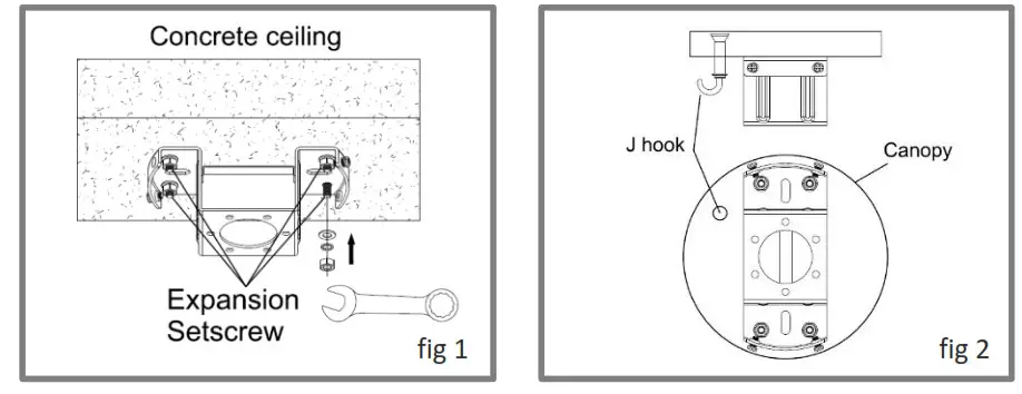
- To use Four Expansion Setscrew to install the hanger bracket firmly (fig 1).
- Install the ‘J’ hook onto the concrete ceiling and fasten firmly. Note the place of ‘J’ hook as (fig 2).
INSTALLATION OF CANOPY:
- Remove the two setscrews, three screws, and reinforced pieces as (fig 3).
- Install the canopy to the main body with the three screws and reinforced piece as (fig 4).
- Keep the two setscrews that will not be used.
INSTALLATION OF CANOPY:
- Remove the two setscrews, three screws and reinforced piece as (fig 3).
- Install the canopy to the main body with the three screws and reinforced piece as (fig 4).
- Keep the two setscrews that will not be used.
PRE-FIX THE FAN:
- Remove the Two screws from the hanger bracket (fig 5). It will be used on step ‘INSTALLATION OF FAN’.
- Attach the safety wire cord to the expansion ‘J’ hook for safety purposes. Tighten the nuts firmly (fig 5).
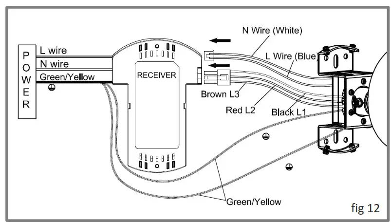
WIRING OF FANS:
- Total three groups of wires from the top of the main body:• White, Blue wires with small connector – for Synchronous Motor• Black(L1), Red (L2), Brown (L3) wires with big connector – for fan• Green/yellow – ground wire

- Plug the connector from the main body into the remote control receiver: big connector to big socket & small connector to small socket.
- Connect remote control receiver wires to AC wires: White to Neutral, Black to Live, Green/Yellow to Ground.
- The earth wire is longer than the safety cord by 60mm and more. When the failure of the suspension system occurs, the current-carrying conductor taut before the earthling conductor and the body of the fan assembly is still effectively earthed.
INSTALLATION OF FAN:
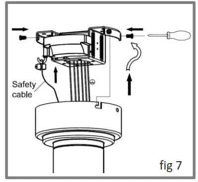
- Unscrew the two screws from the hanger bracket out by ½ (fig 7).
- Align and insert the canopy ‘L’ shape groove to the hanger bracket screws, twist until it is held tight.
- Fix back the two screws which were removed earlier during step ‘PRE-FIX THE FAN’ to the hanger bracket hole and tighten all the four screws firmly (fig 7).
METHOD OF INSTALLATION – WALL MOUNT
INSTALLATION OF HANGER BRACKET:
- Use four Expansion Setscrew to install the hanger bracket to the wall firmly (fig 8).Note: The hanger bracket must be vertical to the floor.
INSTALLATION OF DOWNROD:
- Remove the ‘R’ pin, nut, and cross pin from the downrod.
- Install the canopy and decorative cover through the downrod then thread the wires through the downrod, insert the downrod into the coupler as (fig 9).
- Install back the cross pin, nut and secure with the ‘R’ pin. The ‘R’ pin must be properly installed to prevent the cross pin from working loose. Tighten the two setscrews on the coupler (fig 10).
HANGING OF FAN:
- Remove the ‘R’ pin, nut and cross pin from the coupler on the hanger bracket.
- Thread the wires through the coupler and insert the downrod into the coupler (fig 11).
- Install back the cross pin, nut and secure with the ‘R’ pin. The ‘R’ pin must be properly installed to prevent the cross pin from working loose. Tighten the screws on the coupler through the downrod. Tighten the two setscrews on the coupler (fig 11).
WIRING OF FAN:
- Connect the motor wires, receiver wires and AC wires, follow step ‘WIRING OF FAN’ on page 7.
INSTALLATION OF CANOPY:
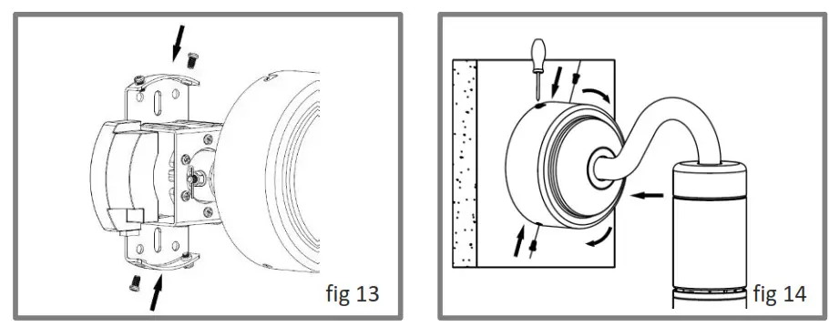
- Remove the two screws from the hanger bracket and unscrew the other two screws from the hanger bracket out by ½. (fig 13)
- Align and insert the canopy ‘L’ shape groove onto the hanger bracket screws, twist until its held tight.
- Install back the two screws which were removed on step (1) to the hanger bracket hole and tighten all four screws firmly. (fig 14)
INSTALLATION OF FAN BLADES:
- Remove the nut from the motor.
- Insert the fan blades and nut to the motor shaft pin. Tighten the nut firmly (fig 15).
- Install and tighten the blade cap.
REMOTE CONTROL MANUAL (Wiring Diagram):
- This manual is to use for the controller of the fan.
- Disconnect power supply before wiring.
- Install the Receiver inside the canopy of the fan to ensure proper protection.
Adopt RF wireless digit emission technique, biunique controlled, the coincident code rate is less than one-millionth.Receiver can be controlled by any angle of the Emitter in prescriptive space and unrestricted by direction.
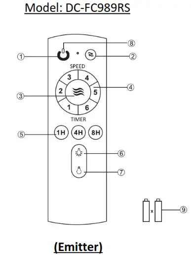
- Fan OFF Button
- 360° Revolve Angle Control (double press to change direction)
- Natural Wind
- Fan Speed
- Timer
- Light ON Button(not applicable for this model)
- Light OFF Button
- LED Indicated Light
- 1.5V Battery x 2pcs
IMPORTANT:
- Insert two size AAA alkaline batteries by matching + and – on the batteries to the diagram inside the battery compartment of the remote control.
- Steps to pair the Emitter and Receiver:i. Turn ‘ON’ the supply power.ii. Within 30 seconds, press and hold the Emitter button ‘ ‘ for 5 seconds until hearing a long ‘beep’ sound.iii. Pairing successfully (learning mode is not acceptable after turning ‘ON’ the supply power for more than 30 seconds).
- When the Emitter cannot control the Receiver, check to surround for any existence of similar remote control products. Some interference might occur when similar radio waves are transmitted.
- Replace the batteries when found low in voltage as it will affect the sensitivity of the Emitter.
- Always remove the batteries from the Emitter when leaving unused for a long period of time.
MAINTENANCE TIPS:
- Because of the fan’s natural movement, some connections may be loose.To check the support connections, brackets and blades attachments 2 times a year. Make sure they are all secured (It is not necessary to dismantle the entire fan from the ceiling).
- Clean your fan periodically to help maintain its appearance over the years. Do not use water when cleaning, use only a soft brush or lint-free cloth to avoid scratching the finish. The plating is coated with a lacquer to minimize the ratio of discoloration or tarnishing which would damage the motor or the wood or possibly cause an electric shock.
- You can apply a light coat of furniture varnishing to the wood for additional protection and enhance its beauty. Surface scratched marks can be touch-up with a light coat of shoe polish.
- There is no need to oil your fan. The motor is created with lubricated sealed ball bearings.
- User are advised to contact the fan supplier to conduct a regular examination of the fan suspension system at least once in every two years.
WARNINGMAKE SURE THE POWER IS SWITCHED OFF AT THE ELECTRICAL PANEL BOX BEFORE YOU ATTEMPT TO ANY REPAIRS (REFER TO THIS SECTION), MAKING ELECTRICAL CONNECTIONS.
TROUBLESHOOTING:
PLEASE CHECK THE FOLLOWING BEFORE LODGING A SERVICE REPORT
| PROBLEM | REASON | SOLUTION |
| Fan not moving | 1) Main cables not connected.2) Check the line wires. | 1) Check mains & subcircuit breakers or fuse.2) Check the line wires connections to the fan & switch housing. |
| Fan noisy | 1) Housing screw loose.2) Wire nut connections rattle against each other.3) Canopy touches the ceiling. | 1) Tighten all screws.2) Separate & store neatly all the wire nut connections.3) Check & ensure the canopy is not touching or too close to the ceiling. |
| Remote control Not working | 1) Remote & receiver pairing out.2) Battery not installed.3) Battery weak | 1) Pairing required – follow page 12, clause 2.2) Install the remote control battery.3) Change new battery. |
NOTES:DRAWING SHOWING THE ASSEMBLY OF WIRES THROUGH FAN MOTOR SHAFT FOR DECORATIVE CEILING FAN
 report this ad
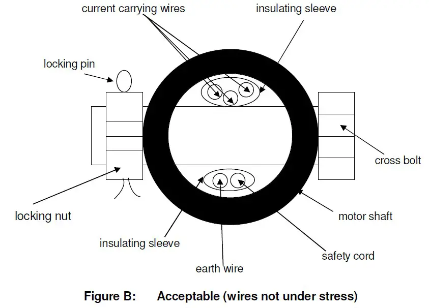
[xyz-ips snippet=”download-snippet”]