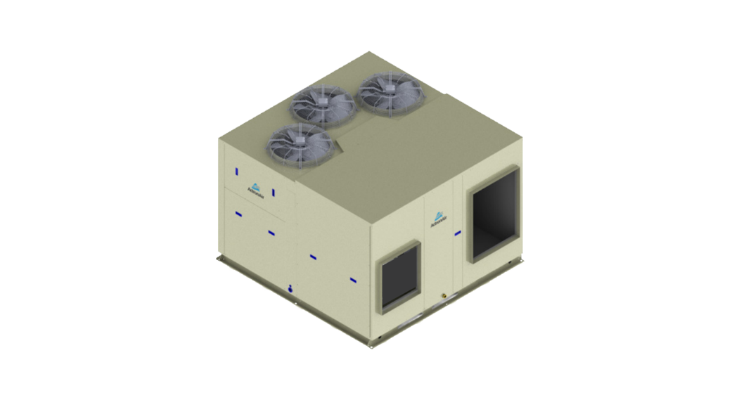
PKY500T Tri-Capacity Commercial Package Unit
Package Tri-CapacityInstallation and Commissioning GuideModel NumbersPKY500T PKY620T PKY700T IMPORTANT NOTE:Please read this manual carefully before installing or operating your air conditioning unit.That’s better. That’s Actron.
Installation and Commissioning Guide
Package Tri-Capacity
TABLE OF CONTENTS
01. INTRODUCTION ………………………………………………………………………………………………………………4
01.01. Product Inspections
4
01.02. Codes, Regulations and Standards
4
02. GENERAL INFORMATION…………………………………………………………………………………………………..4
03. SAFETY PRECAUTION ……………………………………………………………………………………………………….6
04. INSTALLATION INFORMATION ………………………………………………………………………………………….. 7
05. UNIT MOUNTING AND LOCATION………………………………………………………………………………………8
06. COMPONENTS OVERVIEW…………………………………………………………………………………………………9
07. UNIT DIMENSIONS…………………………………………………………………………………………………………. 10
07.01. PKY500T
10
07.02. PKY620T
11
07.03. PKY700T
12
07.04. Base Mounting Details
13
07.05. Service Access Areas and Airflow Clearances
14
08. UNIT LIFTING PROCEDURES………………………………………………………………………………………………15
08.01. Crane Lifting Method
15
08.02. Fork Lift Method
16
09. CONDENSATE AND SAFETY TRAY DRAINAGE INSTRUCTIONS…………………………………………………17
09.01. Suggested Minimum Slope to Ensure Correct Drainage
17
09.02. Suggested Drain Trap Details
18
10. BANKING OF UNITS …………………………………………………………………………………………………………19
10.01. End-To-End Configuration
19
10.02. Cluster Configuration
19
10.03. Side-By-Side Configuration
20
10.04. End-To-End Configuration
20
10.05. Standard Model
21
10.06. Standard Model with Optional 3-Phase Protection Relay
21
10.07. Standard Model with Optional 3-Phase Soft Starters
22
10.08. With Optional EC Outdoor Fans
23
10.09. With Optional EC Outdoor Fans and 3-Phase Protection Relay
23
10.10. With Optional EC Outdoor Fans and 3-Phase Soft Starters
24
11. UNIT PREPARATION……………………………………………………………………………………………………….. 25
11.01. Supply and Return Angle Plate Installation
25
11.02. Supply and Return Angle Plate Assembly/Installation
26
11.03. Electrical Mains and Isolator Installation
27
11.04. Compressor Shipping Blocks Removal
28
11.05. Air Filter Installation
29
12. ELECTRICAL………………………………………………………………………………………………………………….. 30
12.01. Package Electrical Connection
30
12.02. Maximum Cable Lengths
31
12.03. BMS Control Wiring Procedures
32
12.04. Return Air – Outside Air – Spill Air Control Wiring Procedures
33
12.05. Demand Response Management
34
13. CONTROL MENU …………………………………………………………………………………………………………….35
13.01. Menu Navigation
35
13.02. Service Password
35
2
Installation and Commissioning Guide 500-700 Tri-Capacity Package
Doc. No.0525-097 Ver. 4 220217
Installation and Commissioning Guide
Package Tri-Capacity
14. MENU TREE ………………………………………………………………………………………………………………….. 36
14.01. Main/Status Menu
36
14.02. Service Menu
37
14.03. Manufacturer Menu
39
15. EXTERNAL INPUT OPERATION ………………………………………………………………………………………….40
15.01. Unit ON/OFF Configuration
40
15.02. Indoor Fan External Control
40
15.03. Compressor Configuration
42
16. INTERNAL SENSOR OPERATION……………………………………………………………………………………….. 45
16.01. Unit Control Configuration
45
16.02. Unit ON/OFF Configuration
45
16.03. Indoor Fan Configuration
48
17. SETTING UP BMS (REMOTE DEMAND) OPTIONAL ………………………………………………………………. 49
18. SETTING ECONOMY CYCLE OPERATION…………………………………………………………………………….49
18.01. Setting Economy Cycle Type
49
19. ROOM AIR TEMPERATURE SENSOR INSTALLATION ………………………………………………………………51
20. ROOM AIR TEMPERATURE SETUP IN CONTROL INTERFACE ………………………………………………….. 52
20.01. Averaging Four Room Air Temperature Sensors (Optional)
52
20.02. Setting up the Room Air Temperature
53
20.03. Room Temperature Sensor Adjustment Instructions
53
21. AFTER HOURS LOGIC WITH TIMECLOCK (SCHEDULER) …………………………………………………………53
21.01. After Hours wiring to the unit
53
21.02. Operational Logic
54
22. ENABLE / DISABLE AIR FILTER ALARM ………………………………………………………………………………. 54
23. EXTERNAL INPUT WIRING DIAGRAMS…………………………………………………………………………………55
23.01. 24VAC Relay Output Compressors and Indoor Fans
55
23.02. 0-10 Analogue Output Compressor and 24VAC Relay Output Indoor Fans
56
23.03. 24VAC Relay Output Compressor and 0-10 Analogue Output Indoor Fans
57
23.04. Wiring Diagram 0-10 Analogue Output Compressors and Indoor Fans
58
24. FAN PERFORMANCE DATA AND CURVE …………………………………………………………………………….. 59
25. REFRIGERANT CHARGING……………………………………………………………………………………………….. 62
25.01. Charging Method 1: Subcooling and Superheat
62
25.02. Charging Method 2: Cooling Charging Curve
66
25.03. Thermal Expansion Valve (TXV) Adjustment
67
26. FAULT DISPLAY CODES……………………………………………………………………………………………………. 68
26.01. Control Fault Code Displays
68
26.02. Soft Starter Display Codes
69
27. MAINTENANCE …………………………………………………………………………………………………………….. 70
28. MAINTENANCE FREQUENCY CHECKLIST …………………………………………………………………………… 72
29. SENSOR DETAIL …………………………………………………………………………………………………………….. 74
30. START-UP AND COMMISSIONING REPORT…………………………………………………………………………..75
Installation and Commissioning Guide 500-700 Tri-Capacity Package
3
Doc. No.0525-097 Ver. 4 220217
Installation and Commissioning Guide
Package Tri-Capacity
01. INTRODUCTION01.01. Product InspectionsCheck your air conditioning unit and all items against the invoice upon receiving your shipment. Inspect the unit, components and accessories for any sign of damage. If there is any damage to the unit, contact ActronAir Customer Care Department immediately on: 1300 522 722 to obtain a Return Material Authorisation (RMA).Check the unit nameplate to verify the model, serial number, electrical rated specifications are correct.01.02. Codes, Regulations and StandardsThe installer and/or contractor assumes responsibility to ensure that unit installation complies with the relevant council, state / federal codes, regulations and building code standards. All electrical wiring must be in accordance with current electrical authority regulations and all wiring connections to be as per electrical diagram provided with the unit.02. GENERAL INFORMATIONThe ActronAir Ducted air conditioning units are designed for applications where superior performance, high efficiency, reliability, supply air quality and quiet operation are the prime priorities. The units are built with the latest technology, EC indoor fans, low-noise outdoor fans and an intelligent electronic control.For optimum efficiency, your air conditioning unit will deliver just the right amount of cooling or heating capacity you demand. Even in extreme conditions, the unit will still supply the required demand at peak performance.Energy Efficient Refrigeration Circuits The ActronAir Ducted system is designed with a variable capacity refrigeration circuit that delivers only the amount of cooling or heating actually required to maintain your desired comfort at the most optimum efficiency.The refrigeration circuit consists of:· High efficiency scroll compressors · Hydrophilic coated condenser coil designed for optimum performance and efficiency with corrugated fins and riffledtubing · Hydrophilic coated evaporator coil designed for optimum performance and efficiency with lanced fins and riffledtubing · Thermal expansion valve (TXV), to maintain efficiency at different operating conditionsEvaporator Section The evaporator section has EC fans which deliver just the right amount of airflow, depending on requirements. The fans provide superior performance for your comfort at optimum efficiency:· Highly efficient variable speed EC motor that uses less energy than the traditional AC motor. · Capable of high external static pressure application (up to 500 Pa). · Easy indoor fan commissioning via control interface. · Low noise operation.Condenser Section · Scroll compressor · Efficient axial fans with direct drive AC motor · Low noise operation
4
Installation and Commissioning Guide 500-700 Tri-Capacity Package
Doc. No.0525-097 Ver. 4 220217
Installation and Commissioning Guide
Package Tri-Capacity
Electrical Section The electrical section consists of:· EMC filters · Switchgears · 3 Phase motor protection · 7 Segment Display menu and fault code · Adjustable indoor airflow pot · Optional soft start, BMS card, ActronAir Group ControlDurable Design and Construction ActronAir is an Australian manufacturer with proven high quality air conditioning products. Known for their durability and reliable performance, these products are designed and built to withstand the extreme weather conditions.The heavy gauge galvanised steel cabinet, with powder coated Hydrophilic coated finish, resists the toughest conditions. The louvered outdoor coil guard protects the condenser coil from any potential damage brought by hail, stones and other solid objects that may be projected to the unit.Hydrophilic coated condenser coil fins provide protection to your heat exchangers and enhanced heat transfer with increased performance efficiency.System Flexibility ActronAir units are the first choice for office, schools and other air conditioning facilities applications, both for new construction or retrofitting projects.Sustainability and Environmentally Friendly The air conditioning system is supplied with zero ozone depleting R-410A refrigerant, which has no phase out or replacement concern.With cooling and heating performance capacity that are among the best in the market, the ActronAir units are the solution for the reduction of energy consumption, CO2 emission, high fuel dependency and high network grid demand.Refrigerant Handling and Accountability ActronAir strongly urges that all service technicians make every effort possible to reduce the emission of refrigerants to the atmosphere. Everyone must act in a responsible manner to conserve refrigerants in accordance to the industry code of practice.
Installation and Commissioning Guide 500-700 Tri-Capacity Package
5
Doc. No.0525-097 Ver. 4 220217
Installation and Commissioning Guide
Package Tri-Capacity
03. SAFETY PRECAUTION· Only licensed HVAC technicians* should install and service this air conditioning equipment. Improper service or alteration by an unqualified technician could result in significant and major damage to the product or property which may render your warranty null and void. Such unqualified service could also lead to severe physical injury or death. Follow all safety instructions in this literature and all warning labels that are attached to the equipment.· Prevailing WH&S regulations must be observed and will take precedence to the safety instructions contained on this manual. Safe work practices and environment must be the paramount importance in the performance of all the service procedures.· Ensure that unit installation complies with relevant council regulations and building code standards. · All electrical wiring must be in accordance with current electrical authority regulations and all wiring connections to beas per electrical diagram provided. · Secure the fans against accidental contact. Beware of pinch point and sharp edges which can cause cutting injury. · Always wear appropriate PPE, remove any dangling jewellery and protect long hair by wearing a cap. · Make sure that safety guards and panel covers are always firmly secured and not damaged. · This appliance is not intended for use by young children or infirm persons unless they have been adequately supervisedby a responsible person to ensure that they can use the appliance safely. Young children should be supervised to ensure that they do not play with the appliance. · Installer must incorporate a means of electrical disconnection (isolator) in the sub mains fixed wiring in accordance with the latest edition of the AS/NZS 3000 (also known as Australian Wiring Rules). · Secure the power cords and control cables that goes in/out the unit. Use the cable ties provided in the control box. · This unit is fitted with Indoor EC Motors with high power capacitors, which can have dangerous voltages at terminals for up to 5 minutes after main power has been isolated. Wait at least 5 minutes after power isolation and test for high voltage before performing service work. · EC Plug Fan fitted to this unit has dual power supplies, i.e. 400V/3Ph/50Hz motor power supply plus 10VDC control power supply. Care must be taken to ensure both are safely isolated to prevent personal injury and damage to the equipment. · This unit is designed for use with R-410A refrigerant only.*Qualifications required will be appropriate Electrical, Refrigeration and Refrigerant Handling License and Training, dependent on local State/ Territory regulations.DANGERHazardous Voltage – Risk of Electrocution. TURN-OFF the power from main isolator before proceeding with any service work of the unit. Observe proper LOCK-OUT/ TAG-OUT (LOTO) procedures for electrical appliances in order to prevent accidental switching-on of the power supply.WARNINGEC Motors are fitted with high power capacitors and can have dangerous residual voltages at motor terminals after power has been isolated. Wait at least 5 minutes after power isolation and test for any residual voltage before beginning service work.CAUTIONBeware of Rotating Fans! Ensure that indoor and outdoor fans are isolated and have come to a complete stand still before servicing the equipment. Beware of pinch point and sharp edges which can cause cutting injury. Secure the fans against accidental contact. Always wear appropriate PPE and remove any dangling jewellery and protect long hair by wearing a cap. Ensure that no loose clothing can be caught / entangled in moving parts.VISUAL INSPECTION and WORK ASSESSMENTWork areas and conditions must first be assessed and evaluated for any potential hazardous conditions. It is also important to be familiar with the unit parts and components before proceeding with any service task.
6
Installation and Commissioning Guide 500-700 Tri-Capacity Package
Doc. No.0525-097 Ver. 4 220217
Installation and Commissioning Guide
Package Tri-Capacity
04.INSTALLATION INFORMATIONAll service technicians handling refrigerant must be licensed to handle refrigerant gases.Recover and Recycle Refrigerants Never release refrigerant to the atmosphere! It is an offence in Australia to do so. Always recover, recycle and reuse refrigerants. When removing from the system, properly contain and identify refrigerants in its dedicated container for proper disposal and/or storage. Always consider the recycle or reclaim requirements of the refrigerant before beginning the recovery procedures. Obtain a chemical analysis of the refrigerant if necessary. Refer recovered refrigerant and acceptable refrigerant quality to existing standards and regulations.Refrigerant Handling and Safety Consult the refrigerant manufacturer’s Material Safety Data Sheet (MSDS) for information on proper handling and to fully understand health, safety, storage and disposal requirements. Use the approved containment vessels and refer to appropriate safety standards. Comply with all applicable transportation standards when shipping refrigerant containers.Service Equipment and Recovery Procedures Always use refrigerant reclaiming equipment in order to minimise refrigerant emissions. Use equipment and methods which will pull the lowest possible system vacuum while recovering and condensing refrigerant. Equipment capable of pulling a vacuum of less than 500 microns is required.Do not open the system to the atmosphere for service work until refrigerant is fully removed and/or recovered. Perform refrigeration system evacuation, prior to charging, in accordance with AIRAH / IRHACE Refrigerant handling code of practice.Let the unit stand for 1 hour and with the vacuum not rising above 500 microns. A rise above 500 microns indicates a leak from the system and a leak test is required to locate and repair any leak.CAUTION A leak test is always required on any repaired section of the refrigeration system.Charge refrigerant into the system only after the equipment does not leak or contain moisture. Ensure that R-410A is only charged in liquid form. Take into consideration the correct amount of refrigerant charge specified for the system to ensure efficient unit operations. When charging is complete, reclaim refrigerant from charging lines into an approved refrigerant container. Seal all used refrigerant containers with approved closure devices to prevent unused refrigerant from escaping to the atmosphere. Take extra care to maintain all service equipment directly supporting refrigerant service work such as gauges, hoses, vacuum pumps and recycling equipment.
Installation and Commissioning Guide 500-700 Tri-Capacity Package
7
Doc. No.0525-097 Ver. 4 220217
Installation and Commissioning Guide
Package Tri-Capacity
INSTALLATION PREPARATION (Pre-Installation considerations)The following items must be considered before beginning the unit installation:· Verify the unit capacities and ratings with the unit nameplate · Make certain the floor or foundation is level, solid and have sufficient structural strength to support the unit andaccessories weight. · Allow minimum recommended clearances for periodic maintenance and service access. · Allow sufficient space above the unit for the outdoor air discharge. Condenser air inlet, located on the coil side of theunit, requires sufficient airflow clearance for the optimum unit performance. · Note the conditioned supply air and return air location. Ensure sufficient spaces are allocated for these purposes. · Refer connection and location of condensate drain in the unit drawing and dimensions section of this manual. · Wiring connections must be in accordance with the wiring diagram provided with the unit. · Make sure all wirings are in accordance with local electricity authority regulations and standards. · Do not install the unit close to an area where there is a danger of fire due to volatile, explosive, flammable and/orhazardous materials. · Ensure that spaces around the unit are free from any obstructions for optimum unit performance. · Installer to ensure correct size/type that main circuit breaker and cable is installed in unit sub-mains to protect thesub-mains and unit wiring. · Installer to ensure correctly rated residual current device (RCD) is installed as per with the latest edition of theAS/NZS 3000 (also known as Australian Wiring Rules). · Secure the power cords and control cables that goes in/out the unit. Use the cable ties provided in the control box.05. UNIT MOUNTING AND LOCATION1. The units must be installed in accordance with relevant authority regulations. 2. Install the unit on a level and strong foundation. 3. Install anti-vibration rubber or isolation mounts (installer to supply) under all of the unit’s feet to help reduce noiseand minimize vibration transfer through the foundation. Ensure that all anti-vibration rubbers are rated to provide stable support without impairing the unit’s structural integrity. 4. Diameter or width of anti-vibration rubber’s must be at least equal to the width of the actual feet to prevent deformation overtime. 5. Level the unit to ensure good condensate drainage away from the unit. 6. Ample service access areas and minimum space allowance for airflow must be provided. 7. Avoid installing the unit in such a place where there is danger of fire due to leakage of inflammable fluid. 8. Ensure that the spaces around the unit are free from any obstructions for optimum unit performance.
8
Installation and Commissioning Guide 500-700 Tri-Capacity Package
Doc. No.0525-097 Ver. 4 220217
Installation and Commissioning Guide06. COMPONENTS OVERVIEW
Package Tri-Capacity
EVAPORATOR TOP PANELCONDENSER TOP PANELHIGH EFFICIENCY LOW NOISE AXIAL FANCONDENSER HEAT EXCHANGER 1
ACCESS PANEL CORNER
CONDENSER HEAT EXCHANGER 2CONDENSATE DRAINLOUVRE COIL GUARDTHERMAL EXPANSIONVALVE
SCROLL COMPRESSORS
FILTER RAIL EVAPORATOR HEAT EXCHANGERPLUG FAN ACCESS PANELACCESS PANEL ELECTRICALELECTRICAL PANEL ELECTRICAL ACCESS ACCESS PANEL COMPRESSOR
Installation and Commissioning Guide 500-700 Tri-Capacity Package
9
Doc. No.0525-097 Ver. 4 220217
Installation and Commissioning Guide
Package Tri-Capacity
PLUG FAN INDOOR COILOUTDOOR COIL
07. UNIT DIMENSIONS
07.01. PKY500T
2365 O/A
A
B
C
OUTDOOR COIL
OUTDOOR COIL
2305 O/AYY
INDOOR COIL PLUG FAN
DIMENSION (H x W x D) = 1465 x 2305 x 2365 SUPPLY DUCT (H x W) = 650 x 580 RETURN DUCT (H x W) = 900 x 700
THIRD ANGLE PROJECTION
555
605
OUTDOOR COIL 405
670 OUTDOOR COIL
CONDENSATE DRAIN 25.4 (1″) BSP SOCKET
375
OUTDOOR COIL
D
E
XX
100
F
TOP VIEW
2250
100
580
790
700
80
195 335
1265 1465 O/A
900
1390
650
100Unit Air Handing Configuration(LH/RH) LeftHanding RightHanding
ELECTRICAL ACCESS 2335SIDE VIEW
295
405
Unit Weight A
Corner Weights (kg)
B
C
D
E
853 127 171 52 169 254
853 118 189 97 175 207
LIFTING POINT 4 x Ø 20mm
150
CONDENSATE DRAIN 25.4 (1″) BSP
FEMALE THREAD
2290
FRONT VIEW
Centre Of Gravity Position
F
XX
YY
80
1115
1060
67
NOTES:1. Do not scale drawing. All dimensions are in mm unless specified. Refer to corresponding unit dimensional drawing for mounting hole details.2. LH/RH refers to Left Hand or Right Hand location of supply air. 3. Ensure that Service Access Areas and Spaces for Airflow Clearances are met. This is based on the condition that the spaces around theunits are free from any obstructions and a walkway passage of 1000 mm between the units or between the unit and the outside perimeter is available. 4. Minimum service access areas and spaces for airflow clearances are responsibilities of the installer, ActronAir will not be held liable for any extra charges incurred due to lack of access and space for airflow. 5. Under all circumstances, condenser air must not recirculate back onto condenser coil. Keep all clearance free of any obstructions. 6. MTG C-C DIST = Mounting Centre to Centre Distance. 7. Use M12 bolt for feet mounting. 8. Diagrams are left handing. 9. For reverse handling, service clearances for plug fan and airflow clearance for hood will be reversed. If the optional hood is not installed, 500mm clearance is required for service access. Airflow configuration shown is LH for illustration purposes only.
10
Installation and Commissioning Guide 500-700 Tri-Capacity Package
Doc. No.0525-097 Ver. 4 220217
Installation and Commissioning Guide
Package Tri-Capacity
PLUG FAN INDOOR COILOUTDOOR COIL
07.02. PKY620T
2365 O/A
A
B
C
OUTDOOR COIL
OUTDOOR COIL
2305 O/AYY
INDOOR COIL PLUG FAN
DIMENSION (H x W x D) = 1695 x 2305 x 2365 SUPPLY DUCT (H x W) = 650 x 580 RETURN DUCT (H x W) = 900 x 700
THIRD ANGLE PROJECTION
490
670
OUTDOOR COIL 445
330
670 OUTDOOR COIL
CONDENSATE DRAIN 25.4 (1″) BSP SOCKET
OUTDOOR COIL
D
E
XX
125
F
120
580
770
700
100
TOP VIEW
2250
100
80
315 425
1470 1695 O/A
900
1600
650
385
525
100
ELECTRICAL ACCESS 2335
Unit Air Handing Configuration(LH/RH) LeftHanding RightHanding
SIDE VIEWUnit Weight A937 139 937 130
Corner Weights (kg) BCDE 188 57 186 279 207 106 192 228
LIFTING POINT 4 x Ø 20mm
150
CONDENSATE DRAIN
25.4 (1″)
BSP FEMALE THREAD
2290
FRONT VIEW
Centre Of Gravity Position
F
XX
YY
88
1115
1060
74
NOTES:1. Do not scale drawing. All dimensions are in mm unless specified. Refer to corresponding unit dimensional drawing for mounting hole details.2. LH/RH refers to Left Hand or Right Hand location of supply air. 3. Ensure that Service Access Areas and Spaces for Airflow Clearances are met. This is based on the condition that the spaces around theunits are free from any obstructions and a walkway passage of 1000 mm between the units or between the unit and the outside perimeter is available. 4. Minimum service access areas and spaces for airflow clearances are responsibilities of the installer, ActronAir will not be held liable for any extra charges incurred due to lack of access and space for airflow. 5. Under all circumstances, condenser air must not recirculate back onto condenser coil. Keep all clearance free of any obstructions. 6. MTG C-C DIST = Mounting Centre to Centre Distance. 7. Use M12 bolt for feet mounting. 8. Diagrams are left handing. 9. For reverse handling, service clearances for plug fan and airflow clearance for hood will be reversed. If the optional hood is not installed, 500mm clearance is required for service access. Airflow configuration shown is LH for illustration purposes only.
Installation and Commissioning Guide 500-700 Tri-Capacity Package
11
Doc. No.0525-097 Ver. 4 220217
Installation and Commissioning Guide
Package Tri-Capacity
PLUG FAN INDOOR COILOUTDOOR COIL
07.03. PKY700T
2365 O/A
A
B
C
OUTDOOR COIL
OUTDOOR COIL
2305 O/AYY
INDOOR COIL PLUG FAN
DIMENSION (H x W x D) = 1695 x 2305 x 2365 SUPPLY DUCT (H x W) = 650 x 580 RETURN DUCT (H x W) = 900 x 700
THIRD ANGLE PROJECTION
490
670
OUTDOOR COIL 445
670 OUTDOOR COIL
CONDENSATE DRAIN 25.4 (1″) BSP SOCKET
330
OUTDOOR COIL
D
E
XX
125
F
120
580
770
700
100
TOP VIEW 2250
100
80
315 425
1470 1695 O/A
900
1600
650
385
525
100
ELECTRICAL ACCESS 2335
Unit Air Handing Configuration(LH/RH) LeftHanding RightHanding
SIDE VIEW
Unit Weight A
Corner Weights (kg) BCDE
964 143 194 59 191 287
964 134 213 110 197 234
LIFTING POINT 4 x Ø 20mm
150
CONDENSATE DRAIN
25.4 (1″)
BSP FEMALE THREAD
2290
FRONT VIEW
Centre Of Gravity Position
F
XX
YY
90
1115
1060
76
NOTES:1. Do not scale drawing. All dimensions are in mm unless specified. Refer to corresponding unit dimensional drawing for mounting hole details.2. LH/RH refers to Left Hand or Right Hand location of supply air. 3. Ensure that Service Access Areas and Spaces for Airflow Clearances are met. This is based on the condition that the spaces around theunits are free from any obstructions and a walkway passage of 1000 mm between the units or between the unit and the outside perimeter is available. 4. Minimum service access areas and spaces for airflow clearances are responsibilities of the installer, ActronAir will not be held liable for any extra charges incurred due to lack of access and space for airflow. 5. Under all circumstances, condenser air must not recirculate back onto condenser coil. Keep all clearance free of any obstructions. 6. MTG C-C DIST = Mounting Centre to Centre Distance. 7. Use M12 bolt for feet mounting. 8. Diagrams are left handing. 9. For reverse handling, service clearances for plug fan and airflow clearance for hood will be reversed. If the optional hood is not installed, 500mm clearance is required for service access. Airflow configuration shown is LH for illustration purposes only.
12
Installation and Commissioning Guide 500-700 Tri-Capacity Package
Doc. No.0525-097 Ver. 4 220217
Installation and Commissioning Guide
07.04. Base Mounting DetailsPKY500T/PKY620T/PKY700T375
770 MTG C-C DISTANCE
Package Tri-Capacity
770
MTG C-C
DISTANCE
375
64
1167 MTG C-C DISTANCE
1107
32
2334 O/A
1167 MTG C-C DISTANCE
1066
64
32
64
1341
788
64
2289 O/A
*Diagram shown above is the base view from the bottom of the unit.
Installation and Commissioning Guide 500-700 Tri-Capacity Package
13
Doc. No.0525-097 Ver. 4 220217
Installation and Commissioning Guide
Package Tri-Capacity
07.05. Service Access Areas and Airflow Clearances
500 mm AIRFLOW ALLOWANCE
1000 mm SERVICE CLEARANCE (COMPRESSORand ELECTRICALS)
OUTDOOR COIL
OUTDOOR COIL
* For reverse handing, service clearance for plug fan and airflow clearance for hood will be reversed. ** If the optional hood is not installed, 500mm clearance is required for service access.KEEP ALL CLEARANCES FREE OF ANY OBSTRUCTIONS
OUTDOOR COIL500 mm AIRFLOW ALLOWANCE
1000 mm* SERVICE CLEARANCE (PLUG FAN)
556 mm 300 mm* AIRFLOWALLOWANCE
INDOOR COIL
300 mm OUTSIDE AIR SECTION SERVICE CLEARANCE
DUCTWORK
1000 mm FILTER ACCESS
OPTIONAL HOOD**800 mm
DUCTWORK
HEIGHT CLEARANCE = 1500
NOTES:1. Do not scale drawing. All dimensions are in mm unless specified. Refer to corresponding unit dimensional drawing for mounting hole details.2. LH/RH refers to Left Hand or Right Hand location of supply air. 3. Ensure that Service Access Areas and Spaces for Airflow Clearances are met. This is based on the condition that the spaces around theunits are free from any obstructions and a walkway passage of 1000 mm between the units or between the unit and the outside perimeter is available. 4. Minimum service access areas and spaces for airflow clearances are responsibilities of the installer, ActronAir will not be held liable for any extra charges incurred due to lack of access and space for airflow. 5. Under all circumstances, condenser air must not recirculate back onto condenser coil. Keep all clearance free of any obstructions. 6. MTG C-C DIST = Mounting Centre to Centre Distance. 7. Use M12 bolt for feet mounting. 8. Diagrams are left handing. 9. For reverse handling, service clearances for plug fan and airflow clearance for hood will be reversed. If the optional hood is not installed, 500mm clearance is required for service access. Airflow configuration shown is LH for illustration purposes only.
14
Installation and Commissioning Guide 500-700 Tri-Capacity Package
Doc. No.0525-097 Ver. 4 220217
Installation and Commissioning Guide08.UNIT LIFTING PROCEDURES08.01. Crane Lifting Method NOTECrane lifting is recommended over fork lift method.
Package Tri-Capacity
LIFTING POINTLifting Point Is Located At Each Corner Of The Unit (4 Total). Size: Ø20 mmCAUTION WH&S regulations must be observed and will take precedent during lifting process.Equipment required for crane lifting: · 4 x shackles · 2 x nylon slings · Spreader barNOTE Refer to catalogue for unit weight before selecting shackles.Procedure: 1. Remove all screws and washers that secure the unit to the timber pallet. 2. Use 4 x Bow or Dee shackles to connect the lifting holes. 3. Slip nylon slings through all shackles. 4. Ensure slings are protected by rubber pads or similar, if slings are draped across unit edges and corners. This willprevent the unit from being damaged during lifting. 5. SPREADER BAR must be used when lifting the unit.
Installation and Commissioning Guide 500-700 Tri-Capacity Package
15
Doc. No.0525-097 Ver. 4 220217
Installation and Commissioning Guide
Package Tri-Capacity
08.02. Fork Lift MethodProcedure: 1. To move the unit around with the pallet, it is required to insert the fork through the pallet (not the unit feet). 2. Only fork the unit through compressor end (see illustration for location of compressor end).
NOTES· Ensure that the screws and washers are only removed when it is required to disassemble the unit from the pallet.· The length of the fork lift tines need to be at least 1365 mm in length in order to carry the unit. · Before lifting the unit, ensure the tines go past the center line of the unit.
LIFTING THROUGH PALLET PACKAGE UNIT
LIFTING THE UNIT FROM THE PALLET
PALLET
OPTION 1
COMPRESSOR ENDOPTION 2
INSERT FORK LIFT TINES HERE (COMPRESSOR END)
534 TYP
540 410
410
540
90
PALLET HOLE DIMENSIONS
90
ALL DIMENSIONS ARE IN MM.
UNIT HOLE DIMENSIONS
16
Installation and Commissioning Guide 500-700 Tri-Capacity Package
Doc. No.0525-097 Ver. 4 220217
Installation and Commissioning Guide
Package Tri-Capacity
09. CONDENSATE AND SAFETY TRAY DRAINAGE INSTRUCTIONS09.01. Suggested Minimum Slope to Ensure Correct Drainage
CONDENSATE DRAIN CONNECTION Ø 1″ BSP SOCKET
OUTDOOR COIL
TOP VIEW
OUTDOOR COIL
CONDENSER DRAIN MUST BE RUN SEPARATELY FROM THE EVAPORATOR DRAIN
INDOOR COIL
PLUG FAN
RETURN AIRCONDENSATE DRAIN CONNECTION Ø 1″ BSP FEMALE THREAD
SUPPLY AIR
EVAPORATOR DRAIN MUST BE RUN SEPARATELY FROM THE CONDENSER DRAIN
OUTDOOR COIL
FRONT VIEW
ENSURE DRAIN PIPE SLOPES DOWN FROM THE UNIT AT A MIN. OF 10 MM PER METERSIDE VIEW
ENSURE DRAIN PIPE SLOPES
“A”
DOWN FROM THE UNIT AT
A MINIMUM OF 10 MM PER
METER
SEAL WITH SILICONE SEALANT
Installation and Commissioning Guide 500-700 Tri-Capacity Package
17
Doc. No.0525-097 Ver. 4 220217
Installation and Commissioning Guide09.02. Suggested Drain Trap Details
Package Tri-Capacity
EVAPORATOR CONDENSATE TRAYCONDENSATE DRAIN CONNECTION
THE TOP OF THE TRAP MUST BE 125 MM BELOW THE TOP OF THE EVAPORATOR DRAIN CONNECTIONCLAMP BANDS
THE TOP OF THE VENT MUST BE 50 MM HIGHER THAN THE TOP OF THE EVAPORATOR CONDENSATE TRAY
50 MM
250 MM OR HIGH ENOUGH TO MAINTAIN POSITIVE AIR SEAL
CLEAR PLASTIC INSPECTION TUBE4 X PVC ELBOW
125 MM
TRAP
INSTALL A T-PIECE AS AN AIR VENT FOR LONG DRAIN RUNS
DETAIL A
ENSURE DRAIN PIPE SLOPES DOWN FROM THE UNIT AT A MINIMUM OF 10 MM PER METER
NOTES· Parts for the Condensate Trap are not supplied with the unit. · Refer to Unit Dimensions page of the Technical Selection Catalogue for specifications of drain connectors.
18
Installation and Commissioning Guide 500-700 Tri-Capacity Package
Doc. No.0525-097 Ver. 4 220217
Installation and Commissioning Guide
Package Tri-Capacity
10. BANKING OF UNITSNOTES· The suggested Clearance and Airflow Allowances (given above) are the minimum and based on the condition that the spaces around the units are free from any obstructions and walkway passage of 1000 mm between the units or between the unit and the outside perimeter is available.· Minimum service access areas and spaces for airflow are responsibilities of the installer, ActronAir will not be held responsible for any extra charges incurred due to lack of access and space for airflow.· Do not scale drawing.
500 mm AIRFLOW ALLOWANCEOUTDOOR COIL INDOOR COILOUTDOOR COIL INDOOR COILINDOOR COIL OUTDOOR COIL500 mm AIRFLOW ALLOWANCE
10.01. End-To-End Configuration
DUCT WORK
UNIT 11000 mm FILTER DUCT ACCESS WORK
UNIT 1
PLUG
FAN
OUTDOOR COIL500 mm AIRFLOW ALLOWANCE
UNIT 1 1000 mm SERVICE CLEARANCE (PLUG FAN)+ UNIT 1 1000 mm SERVICE CLEARANCE (COMP. and ELEC.)+ UNIT 2 AIRFLOW ALLOWANCE
DUCT WORK
UNIT 21000 mm FILTER DUCT ACCESS WORK
UNIT 2
PLUG
FAN
OUTDOOR COIL500 mm AIRFLOW ALLOWANCE
KEEP ALL CLEARANCES FREE OF ANY OBSTRUCTIONS
UNIT 2 and 3 1000 mm SERVICECLEARANCE (PLUG FAN)+ (COMP. andELEC.)
500 mm AIRFLOW ALLOWANCEOUTDOOR COIL
PLUG FAN
UNIT 3
DUCT UNIT 3 WORK 1000 mmFILTERACCESS
DUCT WORK
HEIGHT CLEARANCE FOR ALL THE UNITS = 1500mm
DUCT WORK
UNIT 3 1000 mmFILTER ACCESS
DUCT WORK
UNIT 1 1000 mmFILTER ACCESS
10.02.
DUCT WORK
Cluster Configuration
UNIT 1 1000 mm SERVICE CLEARANCE (PLUG FAN)
UNIT 1 1000 mm SERVICE CLEARANCE (COMP. and ELEC.)
PLUG FANINDOOR COILUNIT 1OUTDOOR COIL500 mm AIRFLOW ALLOWANCE
OUTDOOR COIL
UNIT 2 1000 mm SERVICE CLEARANCE (COMP. andELEC.) +(PLUG FAN) +UNIT 1 AIRFLOW ALLOWANCE
KEEP ALL CLEARANCES FREE OF ANY OBSTRUCTIONS
500 mm AIRFLOW ALLOWANCEOUTDOOR COIL
500 mm AIRFLOW ALLOWANCEOUTDOOR COILUNIT 3
INDOOR COIL OUTDOOR COILUNIT 2 and UNIT 3 500 mmAIRFLOW ALLOWANCEOUTDOOR COIL
PLUG
FAN
UNIT 2
INDOOR COILPLUG FAN
DUCT WORK
DUCT UNIT 2 WORK 1000 mmFILTER ACCESS
DUCT WORK
UNIT 3 1000 mm SERVICE CLEARANCE (COMP. and ELEC.)
UNIT 3 1000 mm SERVICE CLEARANCE (PLUG FAN)
HEIGHT CLEARANCE FOR ALL THE UNITS = 1500 mm
Installation and Commissioning Guide 500-700 Tri-Capacity Package
19
Doc. No.0525-097 Ver. 4 220217
Installation and Commissioning Guide
Package Tri-Capacity
UNIT 1 1000 mmFILTER ACCESS
DUCT UNIT 3 WORK 1000 mmFILTER ACCESS
10.03. Side-By-Side Configuration
UNIT 1
UNIT 1
1000 mm
1000 mm
SERVICE
SERVICE
CLEARANCE CLEARANCE
(PLUG FAN) (COMP. and ELEC.)
DUCT WORK
DUCT WORK
PLUG FANINDOOR COILUNIT 1OUTDOOR COIL500 mm AIRFLOW ALLOWANCE KEEP ALL CLEARANCES FREE OF ANY OBSTRUCTIONS
OUTDOOR COIL500 mm AIRFLOW ALLOWANCE DUCT WORK
UNIT 2 1000 mmFILTER ACCESS
10.04. End-To-End Configuration(With Optional Hood) ***
500 mm AIRFLOW ALLOWANCEDUCT WORK
UNIT 2
UNIT 2
1000 mm
1000 mm
SERVICE
SERVICE
CLEARANCE CLEARANCE
(PLUG FAN) (COMP. and ELEC.)
PLUG FAN
500 mm AIRFLOW ALLOWANCE
OUTDOOR COIL
UNIT 3
DUCT WORK
OUTDOOR COILUNIT 2 and UNIT 3 500 mmAIRFLOW ALLOWANCEOUTDOOR COIL
OUTDOOR COIL
INDOOR COIL
UNIT 2INDOOR COIL500 mm AIRFLOW ALLOWANCE
PLUG FAN
UNIT 3 1000 mm SERVICE CLEARANCE (COMP. and ELEC.)
UNIT 3 1000 mm SERVICE CLEARANCE (PLUG FAN)
HEIGHT CLEARANCE FOR ALL THE UNITS = 1500mm
KEEP ALL CLEARANCES FREE OF ANY OBSTRUCTIONS
1100 mm
=
UNIT 2
+
SERVICE CLEARANCE
OPTIONAL HOOD **
300 mm * SPACE CLEARANCE556 mm
500 mm AIRFLOW ALLOWANCEOUTDOOR COIL
800 mm OPTIONALHOODOUTSIDE AIR ACCESS
DUCT WORK
UNIT 1 1000 mmFILTER ACCESS
DUCT WORK
UNIT 1
PLUG
FAN
OUTDOOR COIL
OUTDOOR COIL500 mm AIRFLOW ALLOWANCE
300 mm * SPACE CLEARANCE
800 mm OPTIONALHOODOUTSIDE AIR ACCESS UNIT 1 1000 mm SERVICE CLEARANCE (PLUG FAN* COMP. and ELEC.) + UNIT 2 AIRFLOW ALLOWANCE)
556 mm
OUTDOOR COIL
DUCT WORK
UNIT 2 1000 mmFILTER ACCESS
DUCT WORK
UNIT 2
PLUG
FAN
OUTDOOR COIL
INDOOR COIL500 mm AIRFLOW ALLOWANCE
UNIT 2 SPACE CLEARANCEUNIT 2 1000 mm SERVICE CLEARANCE (COMP. andELEC.) +(PLUG FAN*)
HEIGHT CLEARANCE FOR ALL THE UNITS = 1500 mm*For Reverse Handing, Plug Fan service clearance and Optional Hood space clearance will be reversed. ** Remove Optional Hood when service is required for the Plug Fan of the opposite unit. *** Configuration shown is a sample only of the many possibilities of unit banking configurations withOptional Hood application. Provide a 300 mm Space Clearance for the Optional Hood as shown.
PARTS LAYOUT
20
Installation and Commissioning Guide 500-700 Tri-Capacity Package
Doc. No.0525-097 Ver. 4 220217
Installation and Commissioning Guide
Package Tri-Capacity
10.05. Standard Model
CONDENSER FAN SPEED CONTROLCAPACITORS
CONDENSER FAN CONTROL CONTACTORS ISOLATORS
CONTROL
MAIN ELECTRICAL
TRANSFORMER CONTROL GEARS
MAIN TERMINAL BLOCK
230V GPO
10.06.
CM100 CONTROL
CONTROL
CP05
RELAYS CONTROL INTERFACE
Standard Model with Optional 3-Phase Protection Relay
AUXILIARY TERMINAL STRIPS
RESIDUAL CURRENT CIRCUIT BREAKER ANDOVERLOAD
CONDENSER FAN SPEED CONTROLCAPACITORS
CONDENSER FAN CONTACTORS CONTROL ISOLATORS
CONTROL TRANSFORMER
MAIN ELECTRICAL CONTROL GEARS
MAIN TERMINAL BLOCK
230V GPO
CM100 CONTROL
CONTROL
RELAYS
CP05
CONTROL INTERFACE
OPTIONAL 3 PHASE SEQUENCE PROTECTION RELAYW – OPTION
AUXILIARY
RESIDUAL CURRENT
TERMINAL STRIPS CIRCUIT BREAKER AND
OVERLOAD
Installation and Commissioning Guide 500-700 Tri-Capacity Package
21
Doc. No.0525-097 Ver. 4 220217
Installation and Commissioning Guide
Package Tri-Capacity
10.07. Standard Model with Optional 3-Phase Soft Starters
PKY500TCONDENSER FAN SPEED CONTROLCAPACITORS
CONDENSER FANCONTACTORS
CONTROL ISOLATORS
CONTROLLER TRANSFORMER
MAIN ELECTRICAL MAIN TERMINAL
CONTROL GEARS
BLOCK
230V GPO
CM100 CONTROL
CONTROL RELAYS
CP05 CONTROL INTERFACE
PKY620T and PKY700T
CONDENSER FAN SPEED CONTROLCAPACITORS
CONDENSER FAN CONTACTORS CONTROL ISOLATORS
OPTIONAL 3 PHASE SOFT STARTER(Z – OPTION)
AUXILIARY TERMINALSTRIPS
MAIN ELECTRICAL CONTROL CONTROL GEARS TRANSFORMER
RESIDUAL CURRENT CIRCUIT BREAKER ANDOVERLOADMAIN TERMINAL BLOCK
230V GPO
CM100 CONTROL CONTROL RELAYS
CP05 CONTROL INTERFACE
OPTIONAL 3-PHASE SOFT STARTERZ – OPTION
AUXILIARY
RESIDUAL CURRENT
TERMINAL STRIPS CIRCUIT BREAKER AND
OVERLOAD
22
Installation and Commissioning Guide 500-700 Tri-Capacity Package
Doc. No.0525-097 Ver. 4 220217
Installation and Commissioning Guide
Package Tri-Capacity
10.08. With Optional EC Outdoor FansCONDENSER FAN CONTACTORS
CONTROL ISOLATORS
CONTROL TRANSFORMER
MAIN ELECTRICAL CONTROL GEARS
MAIN TERMINAL BLOCK
230V GPO
CM100 CONTROL
CONTROL RELAYS
CP05 CONTROL INTERFACE
AUXILIARY TERMINAL STRIPS
RESIDUAL CURRENT CIRCUIT BREAKER ANDOVERLOAD
10.09. With Optional EC Outdoor Fans and 3-Phase Protection Relay
CONDENSER FAN CONTACTORS
CONTROL ISOLATORS
CONTROL TRANSFORMER
MAIN ELECTRICAL CONTROL GEARS
MAIN TERMINAL BLOCK
230V GPO
CM100 CONTROL
CONTROL RELAYS
CP05 CONTROL INTERFACE
OPTIONAL 3 PHASE SEQUENCE PROTECTION RELAYW – OPTION
AUXILIARY
RESIDUAL CURRENT
TERMINAL STRIPS CIRCUIT BREAKER AND
OVERLOAD
Installation and Commissioning Guide 500-700 Tri-Capacity Package
23
Doc. No.0525-097 Ver. 4 220217
Installation and Commissioning Guide
Package Tri-Capacity
10.10. With Optional EC Outdoor Fans and 3-Phase Soft Starters
PKY500T
CONDENSER FAN CONTACTORS
CONTROL ISOLATORS
CONTROL TRANSFORMER
MAIN ELECTRICAL CONTROL GEARS
MAIN TERMINAL BLOCK
230V GPO
CM100 CONTROL
CONTROL RELAYS CP05 CONTROL INTERFACE
PKY620T and PKY700TCONDENSER FAN CONTACTORS
CONTROL ISOLATORS
OPTIONAL 3 PHASESOFT STARTER Z – OPTION
AUXILIARY TERMINAL STRIPS
RESIDUAL CURRENT CIRCUIT BREAKER ANDOVERLOAD
CONTROL TRANSFORMER
MAIN ELECTRICAL CONTROL GEARS
MAIN TERMINAL BLOCK
230V GPO
CM100 CONTROL
CONTROL RELAYS CP05 CONTROL INTERFACE
OPTIONAL 3 PHASESOFT STARTER Z – OPTION
AUXILIARY TERMINAL STRIPS
RESIDUAL CURRENT CIRCUIT BREAKER ANDOVERLOAD
24
Installation and Commissioning Guide 500-700 Tri-Capacity Package
Doc. No.0525-097 Ver. 4 220217
Installation and Commissioning Guide11. UNIT PREPARATION11.01. Supply and Return Angle Plate Installation Supply Angle Assembly
Package Tri-CapacityReturn Angle Assembly
1. Assemble supply angle short plate and supply angle longplate using the provided rivet as shown above.Materials: · supply angle short plate x 2 pieces. · supply angle long plate x 2 pieces. · rivet x 8 pieces.2. Attach the supply angle assembly onto supply air openingusing provided screws as shown below.Material: · stainless steel screw 12G x 5/8 x 14 pieces.
3. Assemble return angle short plate and return angle longplate using the provided rivet as shown above.Materials: · return angle short plate x 2 pieces. · return angle long plate x 2 pieces. · rivet x 8 pieces.4. Attach the return angle assembly onto supply air openingusing provided screws as shown below.Material: · stainless steel screw 12G x 5/8 x 18 pieces.
NOTE Supply Air/Return Air angle with optional Left Hand or Right Hand side configuration are not factory fitted. These are to be field assembled and fitted by the installer.S/A
R/A
SUPPLY ANGLE ASSEMBLY
RETURN ANGLE ASSEMBLY
NOTES· All screws, rivets and supply return plates are supplied with the unit. · All items are packed and located inside return air plenum (either beside indoor plug fan or on the filter rail). · This assembly instruction is also applicable to the following unit options:(a) supply air side, (b) supply air front, (c) return air side and (d) return air front. · Tools required (not supplied): rivet gun and Phillips screw driver.
Installation and Commissioning Guide 500-700 Tri-Capacity Package
25
Doc. No.0525-097 Ver. 4 220217
Installation and Commissioning Guide
Package Tri-Capacity
11.02. Supply and Return Angle Plate Assembly/Installation
RIVETS
SA/RA – ANGLE SHORT PLATESA/RA – ANGLE LONG PLATE
1. Assemble supply air and return air angle plates using the provided rivet as shown in illustration on left. Materials: 2 Pieces – Supply Angle Short Plate 2 Pieces – Supply Angle Long Plate 2 Pieces – Return Angle Short Plate 2 Pieces – Return Angle Long Plate 24 Pieces – Rivets 32 Pieces – 10G x 1/2 Philip Pan Head Screws 1 Roll – PVC Closed Cell Tape2. Attach the supply angle assembly onto supply air opening by following detail – A procedures below.3. Follow step 2 to attach the return angle assembly.
Unit Assembly
LINE-UP MOUNTING HOLES OF
1
SA AND RA ASSEMBLIES WITH
BASE SA AND RA MOUNTING
HOLES
Supply Angle AssemblyReturn Angle Assembly
2
SCREW-IN SA AND RA
ASSEMBLIES UNTO BASE
DETAIL A Supply Air/Return Air AssemblyInstallation Details.
NOTES
· All bolts, rivets and supply and return plates are
supplied with the unit.
· All items are packed and located inside return air
plenum (either beside indoor plug fan or on the filter
rail)
· Apply PVC closed cell tape (supplied) to adjoining
contact edges before fastening bolts to ensure tight
air seal.
· Tools required (not supplied): rivet gun and socket
A
wrench.
NOTEBottom Supply Air/Return Air angle options are not factory fitted. These are to be field assembled and fitted by the installer.
26
Installation and Commissioning Guide 500-700 Tri-Capacity Package
Doc. No.0525-097 Ver. 4 220217
Installation and Commissioning Guide11.03. Electrical Mains and Isolator Installation
Package Tri-Capacity
B AB
Removal Order: A Pull-Out B Pull-Down to removeElectrical Panel1. Remove Electrical Panel · Remove mounting screws (4 pieces). · Remove Access Panel – Electrical as shown in the aboveillustration
2. Remove Electrical Panel – Compressor · Remove mounting screws (4 pieces). · Remove Electrical Panel – Compressor as shown in theabove illustration.
Secure the cables firmly using the cables ties and clamp provided in thepanels3. Connect electrical and control wirings · Route electrical mains cable, indoor cable connections andwall control wires as shown above. · Refer to electrical section for electrical and controlconnections.
Earth Line 1 Line 2 Line 3Neutral
Main Terminal Block E L1 L2 L3 NMAIN LINE
Installation and Commissioning Guide 500-700 Tri-Capacity Package
27
Doc. No.0525-097 Ver. 4 220217
Installation and Commissioning Guide11.04. Compressor Shipping Blocks Removal
Package Tri-Capacity
B AB
Remove First the Access Panel – Electrical
Large Compressor
Small CompressorLoosen Bolts (4-pieces/Comp.)
Remove the Access Panel – Compressor1. Remove Access Panel – Compressor · Remove the Access Panel – Compressor by following theAccess Panels removal procedure from previous page.
Shipping Blocks2. Loosen the Bolts – Compressor Mounting · Loosen the bolts that hold the compressors down onto theunit (4 pieces each).
Shipping Blocks
Push back the Compressor
Pull away the Shipping Blocks
Large Compressor
Small CompressorTighten Bolts (4-pieces/Comp.)
Shipping Blocks
3. Remove the Shipping Blocks · Push the Compressor back, taking care not to exert too muchforce that may cause damage to the pipes. · Remove the Shipping Blocks by pulling them away. · Repeat the same procedure for the 2nd compressor.
4. Tighten back the Bolts · Firmly tighten the bolts to secure back the compressors ontothe unit. Recommended torque is 131 Nm. It is critically important for the grommet not to be compressed. · Check to make sure that there are no damage to the piping systems.
28
Installation and Commissioning Guide 500-700 Tri-Capacity Package
Doc. No.0525-097 Ver. 4 220217
Installation and Commissioning Guide11.05. Air Filter Installation
Package Tri-Capacity
Air Filters
Access Panel -Air Filter
Mounting Screws
1. Remove Access Panel – Air Filter · Remove mounting screws (2 pieces). · Remove Access Panel – Air Filter as shown in the aboveillustration
Filter Rails2. Install Air Filters · Install Air Filters (6 pieces required) by sliding the filters oneat a time in the provided Filter Rails. · See notes and specifications below.NOTES · Air Filters are not supplied with the unit. · Adequate Air Filters must be supplied and fitted by theInstalling Contractor.
Access Panel -Air Filter
Mounting Screws
3. Replace Access Panel – Air Filter · Replace Access Panel – Air Filter as shown above. · Replace mounting screws, clean and tidy up the airconditioning unit.
AIR FILTER SPECIFICATIONSw
Models
Qty
PKY500T
6
4 PKY620T-700T2
Air Filter Sizes (H x W x T – mm)404 X 621 X 100508 x 621 x 100408 x 621 x 100
Installation and Commissioning Guide 500-700 Tri-Capacity Package
29
Doc. No.0525-097 Ver. 4 220217
Installation and Commissioning Guide
Package Tri-Capacity
12. ELECTRICALNOTES · All electrical work must be carried out by a qualified technician. · Make sure all wiring is in accordance with local wiring rules. · Wiring connections should be made in accordance with the provided wiring diagram. · The unit wiring diagram is located in the Access Panel – Electrical.
12.01. Package Electrical ConnectionLOW VOLTAGE MAINS WIRING (415VAC)EXTRA LOW VOLTAGE DATA CONTROL WIRING (24VAC)
A
CIRCUIT BREAKER
(Field Supplied by Installer)
B
SUB-MAIN TO UNIT
(Field Supplied by Installer)
6 Core (3 Pair) Twisted Pair 7/0.20 (AWG24)Shielded Data Cable (Installer to Provide)or 6 Core Flat 7/0.12 (AWG28) Telephone Cable (Installer to Provide)
WALL CONTROL (Optional)
PACKAGE UNIT
POWER CIRCUIT BREAKER SIZE and CABLE SIZE
Model
Circuit Breaker SizeA
Cable Size * MAIN (4 Core +E)B
PKY500T PKY620T PKY700T
Amps
mm2
50.0
10.0
63.0
16.0
80.0
25.0
* Suggested Minimum Cable Size should be used as a guide only, refer to AS/NZS 3000 “Australian / New Zealand Wiring Rules” for more details.
WIRING DIAGRAM MATRIX
Model
Wiring Diagram
PKY500T
0515-8206
PKY620T
0515-8606
PKY700T
0515-8606
30
Installation and Commissioning Guide 500-700 Tri-Capacity Package
Doc. No.0525-097 Ver. 4 220217
Installation and Commissioning Guide
Package Tri-Capacity
12.02. Maximum Cable Lengths
(OPTIONAL DUAL CONTROL) CONTROL INTERFACE ActronAir CP05/CP10 (Purchased Separately)
Prg Esc
2 CP05 – or – CP10
2
(OPTIONAL REMOTE RE-LOCATION) ActronAir CP05CONTROL INTERFACE** (Factory Supplied)
6 Core (3 Pair) Twisted Pair 7/0.20 (AWG24) Shielded Data Cable(Installer to Provide) or6 Core Flat 7/0.12 (AWG28) Telephone Cable(Installer to Provide)
4
ActronAir LM-RS-2 ActronAir 2060-036
ROOM AIR SENSOR
ROOM AIR SENSOR*
(Optional)
(Factory Supplied)
3
3
– or –
NTC Sensor (Factory Supplied)
Cable Run 1 to 2 1 to 3 1 to 4 1 to 5
1 PACKAGE UNIT
6 Core (3 Pair) Twisted Pair7/0.20 (AWG24) Shielded Data Cable (Installer to Provide)or 6 Core Flat 7/0.12 (AWG28) Telephone Cable (Installer to Provide)5THIRD PARTY CONTROL INPUT TERMINALS
Description Outdoor CM100 to Optional ActronAir CP05/CP10 Control Interface (Dual Control) Outdoor CM100 to Return Air Sensor (NTC Sensor Input Cable Size 0.5mm2 / 1.0mm2) Outdoor CM100 to ActronAir CP05 (Remotely re-located Factory Supplied Control Interface) Outdoor CM100 to Third Party Control
Suggested Maximum Cable Length 50m/200m*** 50m/100m 50m /200m*** Refer to Third Party Control Supplier
NOTES· Diagram shown above is for general representation only. Refer to individual unit wiring diagram for complete wiring connection details.· Long cable runs beside supply mains or TV antenna cables should be avoided where possible. · Room Air Sensor needs to be installed by the installer specific to site requirements. · Suggested Maximum Cable Length: 50m when using Flat Telephone Cable/200m when using 6 Core (3 Pair)Twisted Pair ShieldedData cable. · For compliance with EMC requirements, connect screen wire to Terminal 22 on the Outdoor Panel.* Room Air Sensor is factory supplied with 6m cable as standard. Sensor may need adjustment for longer cable lengths. ** Do not extend the factory supplied data cable when re-locating the Control Interface. Replace the cable with a single length ofeither of the data cables specified above. *** Suggested Maximum Cable Length: 50m when using Flat Telephone Cable/200 m when using 6 Core (3 Pair)Twisted Pair ShieldedData cable.
Installation and Commissioning Guide 500-700 Tri-Capacity Package
31
Doc. No.0525-097 Ver. 4 220217
Installation and Commissioning Guide
Package Tri-Capacity
12.03. BMS Control Wiring ProceduresCONNECT BMS CABLE INTO BMS KIT
OPTIONAL BMS KIT (TO BE PURCHASED SEPARATELY)
J9 FBus 1 J11BMS2
J10
J12 1
J13
Tx/Rx GND J14pLAN
J15 BMS Card
J1
input 24V +10% -15% 50-60Hz / 28-36V
max power: 28W/20W
J2
J3
U6 U7 +Vdc +5VR GND U8 U9 U10 +Vdc +5VR GND
NO1 NC1 NC1 Out2C2 Out3C2
Out4 C2Out5 C2 C2V-IN
J16
J17 J18 J19 J20 J21 J22 J23 J24
C11 NO11 NO12 NO13
NO9 C9NC9 NO10C10 NC10
J27
J28
J25
Tx/Rx GND J29FBus2
J26
J8 2
U12
GND
U11
Y5
DI7H DI7 DI7C DI8 DI8H
J4
J5
J6
J7
GND Y4
Y1
Y2
NO6 C6
Y3
GND D11D9 D12D10 D13DI9C D14
NO7 C7
NO8 C8
GND
Vout G G0
U1 U2 U3 GND 46 U5 +Vdc +5VR GND
NOTE ActronAir Control Interface can be left connected or can be disconnected from the control board.
BMS PART NUMBERS
BMS Connection Type
Kit Part Number *
Order Form**
MODBUS 485 BACNET 485 BACNET TCP/IP
ICMOD-485 ICBAC-485 ICBAC-TCP-IP
Not required Document 1829 Document 1828
* To be purchased separately.
** It is necessary to complete and return the Order Form Document for BACNET cards (will be provided by Customer Care during ordering). The BACNET BMS cards are pre-programmed by ActronAir before being sent out.
DANGERHazardous Voltage ! · Always make sure that all power supply, including remote controls, are disconnected before performing maintenance.Observe proper LOCK-OUT / TAG-OUT (LOTO) procedures to ensure that power cannot be inadvertently energised. Failure to disconnect power before maintenance procedures can result in serious injury or death. · Follow all electrical safety precautions when exposed to live electrical components. · Only qualified technicians are allowed to work on electrical circuits. · All electrical wiring must be in accordance with the relevant electrical authority rules and regulations.
CAUTIONSTATIC SENSITIVE ELECTRONIC DEVICES ! · DO NOT handle electronic devices unless you are wearing an Anti-Static Wrist Strap that is connected to a GOOD EARTH.Failure to protect the electronic devices from static electricity may cause unrepairable damage. · Static damaged electronic devices are NOT COVERED for replacement under warranty.
32
Installation and Commissioning Guide 500-700 Tri-Capacity Package
Doc. No.0525-097 Ver. 4 220217
Installation and Commissioning Guide
Package Tri-Capacity
12.04. Return Air – Outside Air – Spill Air Control Wiring Procedures
Optional Dampers
TERMINALSSecure the cables firmly using the cable ties and clamp provided in the panels.
24VAC Active/Neutral
23 24 25 26 27 28 29 30
Third Party Damper Control
To Outdoor Control
TO MAINS NEUTRAL
TERMINAL
EARTH
EARTH
N
240VAC – N
CB-2
TO FT-2
6A
Refer to diagram below for details of DAMPER connections.
LEGEND:Factory wired and fitted accessories. Installer to supply, wire and fit accessories.
TX
CB-3
72VA
6A
240VAC
24VAC
1
24VAC OUT
TERMINAL
Y4 D19C
OUTDOOR CONTROLJ26
UY5321OUTSIDE AIR DAMPEROPTIONAL FACTORY SUPPLIED ANDFITTED
UY5321RETURN AIR DAMPEROPTIONAL FACTORY SUPPLIED ANDFITTED
UY5321SPILL AIR DAMPEROPTIONAL INSTALLER SUPPLIED ANDFITTED
23
24VAC – ACT
24
24VAC – N
25
(0) 2-10VDC O/A INP
26
(0) 2-10VDC O/A OUT
27
(0) 2-10VDC R/A INP
28
(0) 2-10VDC R/A OUT
29
(0) 2-10VDC S/A INP
30
(0) 2-10VDC S/A OUT
TERMINALS
FIELD WIRING BY THE INSTALLER
THIRD PARTY CONTROL MONITORING
RETURN AIR – OUTSIDE AIR – SPILL AIR CONTROL CONNECTION DIAGRAM
Installation and Commissioning Guide 500-700 Tri-Capacity Package
33
Doc. No.0525-097 Ver. 4 220217
Installation and Commissioning Guide12.05. Demand Response Management
Package Tri-CapacityDRM Control Inputs
TERMINALSSecure the cables firmly using the cable ties and clamp provided in the panels.
7 8 9 11To Outdoor Control
Refer to diagram below for details of DRM connections.
1. Thread and Route the DRM input cables into the Unit · Thread and Route cables as per previous wiring installation procedures.
2. Connect cables into the terminals · Connect cables as shown above and as per wiring diagram provided with the unit.
Demand Management ModeDRM1DRM2DRM3
Description Of ModeCompressor OffMaximum 50% power use mode. (Over each 1/2 hour period)Maximum 75% power use mode. (Over each 1/2 hour period)
Operating ModeCompressors ONLY will cycle OFF and remain off for the entire Demand Response Event.Compressor 1 operation only for the total Demand Response event.Compressor 2 operation only for the total Demand Response event.
OUTDOOR CONTROL
DI1 DI2 DI3 DI4 GND
J7
TERMINALS
DEMAND RESPONSEENABLING DEVICE (DRED)AS4755 COMPLIANT DEVICE (OPTIONAL)
11
COMMON (GND)
10
REMOTE ON/OFF
9
DRM 3
8
DRM 2
7
DRM 1
DRM 3 DRM 2 DRM 1
DEMAND RESPONSE MANAGEMENT CONNECTION DIAGRAM
34
Installation and Commissioning Guide 500-700 Tri-Capacity Package
Doc. No.0525-097 Ver. 4 220217
Installation and Commissioning Guide13. CONTROL MENU13.01. Menu Navigation
Package Tri-Capacity
10:20 Unit: Unit On
Room T.: Supply T.:
19.2oC 16.4oC
Comp
Rev Vlv
Pressing at anytime will bring the menu back one level up. Pressing at anytime will bring back the main menu. Pressing will display an active alarm (if any). Button will blink if any system alarm is active.
Example below will show the navigation to screen Gfc2. Thermoregulat.
G. Service Gf. Service settings Gfc. Thermoregulation Gfc2. Thermoregulat.1. To get into the main menu in the control interface, press . The display will show the list of available submenus. Press or button to scroll through the sub menus and select G. Service. Press to enter the submenu.
Main Menu
A
Main Menu
G
A. On / Off Unit
B. Setpoint
+50oC -10oC
C. Mode of Operation
F. Alarm History G. Service H. Manufacturer
2. Press or button to scroll to menu Gf. Service settings then press . Press or button to scroll to menu Gfc. Thermoregulation then press .
Service Menu
Gf
d. Working hours
e. Communicate config. f. Service settings
Service Menu
Gfc
a. Working hour set
b . Probe adjustment c . Thermoregulation
3. Press or button to scroll to menu Gfc2. Thermoregulat. then press . Set the fields based on desired configuration.
Thermoregulat. Room Temperature
Gfc2
After Hours SW & Temp
Probe weight Value :
0
Room Temp :
13.8OC
Wall Cont Temp :
25.4OC
Control Value :
13.8OC
13.02. Service PasswordTo access the Service Settings pages a password is required: 7378G. Service Gf. Service settings Change password to 7378
Service Password
Insert service password (PW1) :
7378
Service Password is shown.
WARNINGUnauthorized access to Service Menu and inadvertent changes to the settings can cause damage to the air conditioning system which will render ActonAir warranty null and void.
Installation and Commissioning Guide 500-700 Tri-Capacity Package
35
Doc. No.0525-097 Ver. 4 220217
Installation and Commissioning Guide14. MENU TREE14.01. Main/Status Menu*Available when enabled via Service Menu. Main Menu
A. On / Off Unit A1. Turn Unit – ON/OFF/FAN ONLY
A2. Display Backlight – Auto/ON/OFF
B. Setpoint
B1. Setpoint Temp. Setback – Enable/Disable Cooling Limit/ Heating Limit
+50oC -10oC
C. Mode of Operation
C1. Operation Mode
Mode
Cool Only
Heat Only
Auto Change Over
Fan Speed (Optional 3-Speed) Low
Medium
High Fan ModeContinuous
Auto Cycle
D. Clock / Scheduler
D1. Set the Day, Date, Time, Scheduler – Enable/DisableD2. Day Light Saving Time Enable / DisableD3-D6. 7 Days Schedule Start / End D7. After Hours Duration Setting D8-D19. Special Days SettingE. Status
E1-E3. Disch Temp (Crt 1,2 and 3) OD Coil Temp (Crt 1 and 2) Room Temp CO2 Sensor Outside Air Temp External ID Fan Speed Status External Capacity Status
Package Tri-CapacityNote: To scroll Up or Down from existing menu, press or button.E4. Indoor coil temp Room Temp Indoor 0-10V in Indoor Pot val. Indoor CurrentE5. Demand Management 1 Demand Management 2 Demand Management 3 A/Hours Input StatusE6. HP Status LP StatusE7. Stage 1, 2 and 3 Call Heat Mode CallE8. Digital Inputs Indoor Fan Board Fan Fault, Dip SwitchesE9. Supply Fan Speed Status Condenser Fan Speed Status Economy Cycle Output StatusE10-E12. Ref. Circuit (1,2 and 3) Compressor Status Reversing Valve Status Cond Fan Low Spd Status Cond Fan Hi Speed StatusE13. Output 8: On/OffE14. Indoor Fan Board Indoor Fan 1: On/Off Indoor Fan 2 On/Off Supply Fan 1: PWM Supply Fan 2: PWM Aux Relay ON/OFFE15. Indoor Fan Board Anti-freeze Level 1, 2, 3 On/OffE26. Indoor Fan Board Current Mode: Unit Select:E27. Minimum Outside Position Internal/BMS/CO Sensor2Economy Output (%) Damper Command (V)E28. RS485 Outside Probe* Temperature/Humidity Dew Point/EnthalpyE29. RS485 Room Probe* Temperature/Humidity Dew Point/EnthalpyF. Alarm HistoryLog 1 – Recent AlarmUP TOLog 100 – Recent AlarmReset Alarm Log
36
Installation and Commissioning Guide 500-700 Tri-Capacity Package
Doc. No.0525-097 Ver. 4 220217
Installation and Commissioning Guide
Package Tri-Capacity
(PASSWORD PROTECTED)
(PASSWORD PROTECTED)
14.02. Service MenuMain MenuG. Service Ga. Change Language Ga1. Enter Language Change Ga2. Disable Language Mask at Startup: Yes/No Gb. Information Gb1. Software Information
Gfc. ThermoregulationGfc1. Room Temp. Setpoint Dead Band Cooling Prop band Heating Prop band Integral timeGfc2. Room Temp use ID sensor After Hours (SW & Temp./SW Only) Probe weight value Room Temperature Wall Control Temp. Control ValueGfc4. Supply Fan Speed Min/Med/Max Supply Fan Temp. Min/Max
Gb2. Hardware Information Gb4. Fan Board Information Gc. Board Switch
Gfc5. Supply fan Gen. 3/Continuous : Y/N Cycle on de-ice Setting : Y/N Number of Fan Speed Setting Supply Fan Run On Setting Heat Start Delay Setting
Unit Address Switch to Unit Gd. Working LogGd1. Indoor Fan Hr Run / Filter hr Comp. Hr Run(Crt 1,2 and 3)Gd2. Setpoint logging / ResetGd3. Supply Fan logging / ResetGe. Communicate ConfigGe1. BMS Configuration Address Protocol Speed (baud rate)Ge2. Enable BMS to Turn the Unit On/Off On loss of Comms On/OffGe3. Enable DIN4 to Turn the Unit On/OffGf. Service Setting
Gfc6. Room Setpoint limit Minimum / Maximum by User User Setpoint Lock/Unlock User mode sel. Lock/Unlock Mode Lock Timer SettingGfc7. Enable Night Mode by Sched. Start/Stop Finish Time Max Cond fan spd & cct 2 max spdGfc8. Sensor present: Multi Input 1/2: Y/N Supply Air Temp ECcOo2nSoemnsyoErnable Night Mode Enable 0-10V Stage Cont 0-10V In Fan Spd View Only Input Phase Fail RelayGfc11. Unit Mode Configuration Supply Fan Control Setting Select Wall ControlGfc12. Unit Configuration Series, Model & VariationsGfc13. Type of Fans Fitted Supply / Outdoor Outdoor Init Speed (%) & OF1/OF23 Econ. cycle fitted: Y/N Econ. cycle type: Mod:On/Off
(PASSWORD PROTECTED)
Gfa. Working Hour setGfa1. Indoor Filter Filter Fault Rly Y/N Indoor Fan Compressor
Gfc14. Default Initialisation Erase User settings and install global default value Y/NGfc15. Room Temp / Humidity Gfc16. Outside Temp / HumiditySensor fitted/Use this temp sensor
Gfa2. Reset ID Fan / Filter / Comp.Gfb. Probe AdjustmentGfb1. Room Temp. Calibration Multi Input Calibration
Gfc17(OD) – Gfc18(ID). Alarms Disable Rtn Air Sensor Y/NGfc19. Damper Scaling Command Start / End Output Start / EndGfc31. CO Control Start / End 2 Alarm Output: enable/Disable Sensor Fault
(PASSWORD PROTECTED)
Gfc32. Compressors 1st Stage Start / Stop 2nd Stage Start / Stop 3rd Stage Start / Stop
Installation and Commissioning Guide 500-700 Tri-Capacity Package
37
Doc. No.0525-097 Ver. 4 220217
Installation and Commissioning Guide
Package Tri-Capacity
(PASSWORD PROTECTED) (PASSWORD PROTECTED)
Main Menu
(PASSWORD PROTECTED)
G. ServiceGf. Service Setting (cont…)Gfd. Economy SettingsGfd1. Min Outside Air Enable CO Yes/No2CO Level Damper Pos. 2Gfd2. Economy Cycle Enable Yes/No Temp. Difference Outside Air Min Limit Yes/No Temp.:Gfd3. Economy Cycle Outside Air Max Limit Yes/No Temp.:Gfd4. Economy Cycle Enthalpy Yes/No Difference:Gfe. User Default Password is set by ManufacturerGg. Manual ManagementGg1. Compressors Configuration Reversing Valves ConfigurationGg2. Condenser Fans Configuration Relay 8 On/OffGg3. Analogue Output Supply Fan Signal Condenser Fans Signal & Max speeds Economy DampersGg4. Reset overrides Speed up timers Cancel current timeoutsGg5. Test mode for outputs OFF/Heat/Cool/Cycle All/ Defrost compressor: off heat mode:off defrost: off(PASSWORD PROTECTED)
38
Installation and Commissioning Guide 500-700 Tri-Capacity Package
Doc. No.0525-097 Ver. 4 220217
Installation and Commissioning Guide
Package Tri-Capacity
14.03. Manufacturer Menu
Main Menu
(PASSWORD PROTECTED) (PASSWORD PROTECTED)
H. ManufacturerHa. ConfigurationHa1. Unit Configuration Unit Series / Model VariationsHa2. Compressor Configuration Number of compressors Type of compressor logicHa3. ID & OD Fans Configuration Number of fans fitted Type of fans fittedHa4. Unit Control Mode Setting Supply Fan Control Setting Outdoor Fan Control Setting E.E.V.’s Fitted Yes/NoHa5. CO2 Function Econ. Cycle Enable/Disable Econ. On/Off/On Delay Delta Air Equiv. Refrigerant Type Econ. TypeHa6. Sensors Configuration Low Pressure Sensor Suction Temperature Sensor Discharge Temp. Sensor Outdoor Coil Sensor Room Air Temp. SensorHa7. Discharge Temp. Sensor Outdoor Coil Sensor Room Air Temp. Sensor Outside Air Temp. Sensor Multi Inputs (1&2) Yes / NoHa9. ID Fan Board Sensor present Coil / Aux Sensors YES / NOHa10. LP / HP switch config.Ha11. Compressor Power Factor Correction SettingHa12. ID Fan Dipswitch SettingHb. I/O ConfigurationHb1-Hb19. Sensors I/O Config. Alarm Delay Setting DIN Config. DIN Tests Wall Control Config. Multi input 1&2Hc. Factory SettingsHc1. Enable unit On Off By Digital input By Supervisor
(PASSWORD PROTECTED)Hd. InitializationHd1. Default Initialisation Erase User settings and install global default value Y/NHd2. Change service passwordHe. Input / Output TestHf. Probe AdjustmentHf1. LP1&2 / CoilT1 CalibrationHf2. Discharge 1. Temp Cal.: CoilT2 Input B6Hf3. Discharge 2 Temp Cal: OD Coil 2 Sensor Room Temp SensorHf4. Outside Temp. Sensor Multi Input 1 Multi Input 2Hf6. ID Fan Board Coil/Aux Temperature CalibrationHg. ThermoregulationHg1. De-ice Temp. / SettingsHg2. De-ice TimingsHg3. Comp. delay / TimingHg4. Reversing Valve timings Crankcase Heater SettingHg5. OD Fans speed Cooling Temp. SettingsHg6. OD Fans speed Heating Temp. SettingsHg7/8. Outdoor Fans Speed Min / Mid / Max Start pulseHg9. Room Temp Alarm Settings Supply Temp Alarm Settings Alarm delayHg10. Room setpoint limits User setpoint Lock/Unlock User mode Lock/Unlock Mode Lock Timer Mode statusHg11. Supply Fan Min / Mid / Max Speed Supply Fan Temp. Min. / Max TempHg22. Outdoor EC Fan Stage 1 Speed: ByPass1,2,3,4Hg23. Outdoor EC Fan Stage 2 Speed: ByPass1,2,3,4(PASSWORD PROTECTED)
Installation and Commissioning Guide 500-700 Tri-Capacity Package
39
Doc. No.0525-097 Ver. 4 220217
Installation and Commissioning Guide
Package Tri-Capacity
15. EXTERNAL INPUT OPERATION
The System is controlled by Third Party Control through wired inputs. (On/Off, Indoor Fan, Compressor, Heat/Cool and Economy) REMOTE ON/OFF can only be used when Enable Scheduler is set to NO (on screen D1).15.01. Unit ON/OFF ConfigurationThe unit ON/OFF can be configured as follows:
15.01.01. Wiring ON/OFF InputUnit ON/OFF can be wired using either Method 1 (REMOTE ON/OFF) or Method 2 ( IN-FAN (24 VAC IN)) as shown below:Method 1:Unit ON/OFF is configured by switching REMOTE ON/OFF to COMMON.
TERMINALS11 COMMON (GND) 10 REMOTE ON/OFF
Method 2: IN-FAN is operated by switching 24 VAC. The unit will turn On or Off when the switch is closed or open respectively.
TERMINALS
6 IN-FAN (24VAC IN)
1
24VAC OUT
15.01.02. Setting ON/OFF InputSet Enable DIN 4 to turn the unit On/Off : to Yes.
Bms Config.
Ge3
Enable DIN 4 to turn
the unit On / Off : Yes
Yes
The Unit ON/OFF is now configured.
15.02. Indoor Fan External ControlIndoor Fans can be configured to be controlled via a 0-10VDC external input.NOTES · Commissioning of the EC Fans should be carried out by a qualified technician only. · Make sure that all instructions are followed accordingly. · Ensure that connecting duct work and air filters are installed accordingly.
40
Installation and Commissioning Guide 500-700 Tri-Capacity Package
Doc. No.0525-097 Ver. 4 220217
Installation and Commissioning Guide
Package Tri-Capacity
1. Refer to Section 25 for Fan Performance Data or the Fan Curve specific to your air conditioner. 2. Determine the Required Fan Speed (%) which matches your Airflow and External Static Pressure requirements using eitherthe Fan Performance Data or the Fan Curve. Example:Unit Model: PKY620T Airflow: 3200 l/s External Static Press: 100 Pa Required Fan Speed: 62.9% The Required Fan Speed shall be used to commission the indoor fan.
Configuration Procedure:a. On screen C1, set the Fan Mode to operate in either Continuous or Auto cycle (Auto cycle will cycle the indoor fans on/off with the compressor).
Heat / Cool Mode: AUTO CHANGE OVER Fan mode: Auto cycle
C1Select Auto Cycle or Continuous Indoor Fan operation
b. Enable the Multi Input 1 (U11) to the Indoor Fans via S. Configuration screen Gfc8.
G. Service Gf. Service settings Gfc. Thermoregulation Gfc8. S. Configuration
S. ConfigurationSensor present : Multi Input 1 :*Supply Air Temp.* Probe type:Multi Input 2 :
Gfc8YES NTC NO
Change Multi Input 1 to YES
NOTE: Multi Input 2 (U12) can also be enabled, in lieu of Multi Input 1, if not used for other system Components.
c. Configure Multi Input 1 (or Multi Input 2) to 0-10VDC Fan Speed and Probe type to 0-10V: G. Service Gf. Service settings Gfc. Thermoregulation Gfc8. S. Configuration
S. ConfigurationSensor present : Multi Input 1 :*0-10v IN FAN SPD.* Probe type: Multi Input 2 :
Gfc8YES 0-10V NO
YES Change to *0-10v IN FAN SPD.* Change Probe type to 0-10 V
d. Set the Supply Fan type to VARI SPEED via S. Configuration screen Gfc13:
G. Service Gf. Service settings Gfc. Thermoregulation Gfc13. S. Configuration
S. ConfigurationType of fans fitted : Supply : VARI SPEED Outdoor : 2 SPEED AC Outdoor Init Speed OF1: 60.0% OF23: 60.0% Econ. cycle fitted : Yes Econ. Type: Modulate
Gfc13
Change to VARI SPEED
Installation and Commissioning Guide 500-700 Tri-Capacity Package
41
Doc. No.0525-097 Ver. 4 220217
Installation and Commissioning Guide
Package Tri-Capacity
e. Set the unit control mode to EXTERNAL INPUT and set the Supply Fan Control to External via S. Configuration screen Gfc11:G. Service Gf. Service settings Gfc. Thermoregulation Gfc11. S. Configuration
S. ConfigurationUnit control mode : EXTERNAL INPUTSupply Fan Control : EXTERNALSelect Wall Control: SINGLE CL01
Gfc11
EXTERNAL INPUT EXTERNAL
NOTE: The Indoor Fans are now configured/ready to be controlled through external 0-10VDC input.NOTES· Refer to Section 16.02 (a) Indoor Fan Operation Modes for configuring the Indoor Fans in either Continuous Mode or Auto Mode.· If there is no voltage supplied to the indoor fan and it is selected as continuous, the fan will run on the minimum speed for the selected unit model when the unit is On.· The requested external fan speed value will be displayed on the status menu as Voltage x 100 e.g. 5.9 volts will be displayed as 590 on the capacity screen.
Main Menu
E. Status E2. Input / Output
Input / Output
E2
** Analogue Inputs **
Discharge 2 Temp :
13.5oc
Out Coil 2 Temp. :
15.9oc
Room temp. :
22.6oc
Out. Air temp. :
16.0oc
Ext. InFan Spd. :
590
Ext. Capacity :
330
If the Indoor Fan Ecternal Control is set via Multi Input 1, the status screen will show Ext. InFan Spd.If the Compressors 0-10VDC External Control Mode is set via Multi Input 2, the status screen will show Ext. Capacity. e.g. 330 = 3.3V or 33% Spd
15.03. Compressor ConfigurationExternal input modes can be set up as per table below:
Component Compressors
External Input Configuration24VAC 0-10VDC
Compressor ConfigurationProcedure16.03.0116.03.02
Wiring Diagram24.01 24.02
To configure the External Input of Compressors control combination, perform the specific configuration procedure for the Compressors, as detailed below:Unit control mode is set to EXTERNAL INPUT via Gfc11 screen.G. Service Gf. Service settings Gfc. Thermoregulation Gfc11. S. Configuration
S. Configuration Unit control mode : EXTERNAL INPUT Supply Fan Control :Select Wall Control : SINGLE CL01
Gfc11
EXTERNAL INPUT
42
Installation and Commissioning Guide 500-700 Tri-Capacity Package
Doc. No.0525-097 Ver. 4 220217
Installation and Commissioning Guide
Package Tri-Capacity
On screen C1, set the Mode to AUTO CHANGE OVER, so the Third Party Control will have full control of the compressor operation. By setting the mode to Cool only will restrict the compressor operation to Cool only. By setting the mode to Heat only will restrict the compressor operation to Heat only. Auto cycle will cycle the indoor fans on/off with the compressor.
Heat / Cool Mode: AUTO CHANGE OVER Fan mode: Auto cycle
C1AUTO CHANGE OVER/HEAT/COOL Options
15.03.01. Compressors 24VAC External Control ModeCompressors are configured through a 24VAC input from the external control. This is the DEFAULT compressor configuration. If this is the compressor external input requirement, no control interface configuration is required. Refer to the wiring diagram for wiring connection.
TERMINALS
4 STAGE 3 (24VAC IN)
3 STAGE 2 (24VAC IN)
2 STAGE 1 (24VAC IN)
1
24VAC OUT
15.03.02. Compressors 0-10VDC External Control ModeCompressors can be controlled through a 0-10VDC input from the external control.NOTE If a 0-10V input is required the multi-input must be changed as shown per procedure.Compressors Configuration Procedure for 0-10VDC External Control Mode: Assign a Multi Input to the Compressors via S. Configuration screen Gfc8: G. Service Gf. Service settings Gfc. Thermoregulation Gfc8. S. Configuration Ensure that the Multi Input assigned to the Compressors is set to *0-10v STAGE CONT.* and the Probe type: is set to 0 – 10V. G. Service Gf. Service settings Gfc. Thermoregulation Gfc8. S. Configuration Example shown below is for Compressors with external input assigned to Multi Input 2:
S. Configuration Sensor present :Multi Input 1:Multi Input 2: *0 – 10v STAGE CONT. *Probe type:
Gfc8 NO YES 0 – 10V
YES *0 – 10 v STAGE CONT.* 0 – 10V
TERMINALS15 MULTI INPUT 2 14 COMMON (GND)
0-10V DC V
Installation and Commissioning Guide 500-700 Tri-Capacity Package
43
Doc. No.0525-097 Ver. 4 220217
Installation and Commissioning Guide
Package Tri-Capacity
NOTEFor W-3 Phase Sequence Relay Option, Multi Input 2 (U12) is already used for 24VAC supply. Multi Input 1 (U11) must be used instead.
Multi Input 1 and Multi Input 2 state Examples of equivalent voltage and capacity scaling are as follows: 3V = 33% capacity (stage 1); 6V = 66% capacity (stage 2); 9 = 100% capacity (stage 3)Main Menu E. Status E2. Input/Output
Input / Output
E2
** Analogue Inputs **
Discharge 2 Temp :
13.5oc
Out Coil 2 Temp. :
15.9oc
Room temp. :
22.6oc
Out. Air temp. :
16.0oc
Ext. InFan Spd. :
590
Ext. Capacity :
330
If Multi Input 1 is configured (as per Section 16.02 (b, c and d)): External indoor fan speed set on the Third Party Control will be displayed.If Multi Input 2 is configured (as per Section 16.03.02): External capacity set on the Third Party control, will be displayed on the Control Interface e.g. 330 = 3.3 V or 33% Spd
15.03.03. Unit Heat Digital InputHeating is operated by switching 24VAC. The unit will run in heating when the switch is closed. Note that the compressor requires separate signal. Refer to Section 16.03.
HEATING
TERMINALS
5 HEAT (24VAC IN)
1
24VAC OUT
COOLING
TERMINALS
5 HEAT (24VAC IN)
1
24VAC OUT
15.03.04. Economy Cycle On/Off Digital InputIn this mode of Damper operation (On/Off), the damper will be: 1. Closed when the unit is OFF. 2. Open to Max Outside Air Damper (100%) position when Multi Input 1 (or 2) is switched to GND (0V) and the unit is ON. 3. Open to Min Outside Air Damper position when Multi Input 1 (or 2) is open (disconnected from GND (0V)) and the unit is ON.Set the Econ. type to ON/OFF on Gfc13
S. Configuration
Type of fans fitted
Supply : 3 SPEED (EC)
Outdoor : VARI SPEED
Outdoor Init Speed
OF1: 60.0% OF23: 60.0%
Econ. cycle fitted :
Yes
Econ. type :
ON / OFF
Gfc13
Setup Multi Input 1 (or 2) to ECONOMY ENABLE and Probe type to ON/OFF as shown below: G. Service Gf. Service settings Gfc. Thermoregulation Gfc8 S. Configuration
S. ConfigurationSensor present : Multi Input 1 :*ECONOMY ENABLE * Probe type: Multi Input 2 :
Gfc8YES ON/OFF NO
YES *ECONOMY ENABLE* ON/OFF
44
Installation and Commissioning Guide 500-700 Tri-Capacity Package
Doc. No.0525-097 Ver. 4 220217
Installation and Commissioning Guide
Package Tri-Capacity
Switch Multi Input 1 (or 2) to COMMON (GND) to operate the Economy Cycle (Maximum Outside Air)
TERMINALS15 MULTI INPUT 2 14 COMMON (GND) 13 MULTI INPUT 1
ECONOMY ON/OFF DIGITAL SIGNAL
15.03.05. Min. Outside Air: (Configurable in Gfd1 screen)
Min Outside Air Enable CO2: Damper Position
Gfd1 NO 20.0%
NO Set to application requirement
SCREEN WHEN CO IS DISABLED 216. INTERNAL SENSOR OPERATIONThe System is controlled by the ActronAir CM100 control. (On/Off, Indoor Fan, Compressor, Heat/Cool and Economy)
16.01. Unit Control ConfigurationSet the unit control mode to INTERNAL SENSORS via Service menu: G. Service Gf. Service settings Gfc. Thermoregulation
Gfc11. S. Configuration
16.02.
S. Configuration Unit control mode : INTERNAL SENSORSSupply Fan Control :Select Wall Control: SINGLE CL01Unit ON/OFF Configuration
Gfc11 INTERNAL SENSORS
The unit ON/OFF can be configured to one of the following:
Option 1: MANUAL ON/OFF Option 2: TIME SCHEDULER Option 3: EXTERNAL UNIT ON/OFF
Unit status will be shown on the Main Menu. Screen below shows Unit status as Unit On.
10:20
Unit: Unit OnRoom T.: Supply T.:
19.2oC 16.4oC
Comp
Rev Vlv
Unit Status
Installation and Commissioning Guide 500-700 Tri-Capacity Package
45
Doc. No.0525-097 Ver. 4 220217
Installation and Commissioning Guide
Package Tri-Capacity
Option 1: MANUAL ON/OFF Ensure that Enable DIN 4 to turn the unit On/Off : is set to NO.
Bms Config. Enable DIN 4 to turn the unit On / Off : NO
Ge3NO
Turn ON or OFF the unit on screen A1 when required.
On / Off Unit
A1
FAN ONLY
ON
OFF
NOTE Selecting FAN ONLY will turn on the supply fan without compressor operation.The Unit ON/OFF is now configured.
Unit ON/OFF CP05 (CP10, CL01 optional)ON OFF
Unit StatusUnit On OFF by KEY
Option 2: TIME SCHEDULER Ensure that Enable DIN 4 to turn the unit On/Off : is set to NO.
Bms Config. Enable DIN 4 to turn the unit On / Off : NO
Ge3NO
Ensure Enable Scheduler (on screen D1) must be Yes.
Clock Day :Date : Hour :Enable Scheduler :
D1 Tuesday
17/05/16 12:38
YES
YES
46
Installation and Commissioning Guide 500-700 Tri-Capacity Package
Doc. No.0525-097 Ver. 4 220217
Installation and Commissioning Guide
Package Tri-Capacity
Then set the weekly, After Hours and special days time scheduler via screens (D3 D19) to your requirements. The Unit ON/OFF is now configured.
Unit ON/OFF CP05 (CP10, CL01 optional)ON ON OFF
SCHEDULEON OFF ON or OFF
UNIT STATUSUnit On OFF by SCH OFF by KEY
Option 3: External Unit ON/OFF The Unit ON/OFF can be controlled via external relay.
Unit ON/OFF CP05 (CP10, CL01 optional)ON ON OFF
REMOTE ON/OFFON OFF ON or OFF
UNIT STATUSUnit On OFF by DIN OFF by KEY
16.02.01. Wiring ON/OFF InputUnit ON/OFF can be wired using either Method 1: External Unit ON/OFF or Method 2: IN-FAN (24VAC IN). Method 1: External Unit ON/OFF External Unit ON/OFF is operated by switching REMOTE ON/OFF to COMMON.
TERMINALS11 COMMON (GND) 10 REMOTE ON/OFF
Method 2: IN-FAN (24VAC IN) External Unit ON/OFF is operated by switching 24VAC to IN-FAN terminal.
TERMINALS
6 IN-FAN (24VAC IN)
1
24VAC OUT
16.02.02. Setting ON/OFF InputSet Enable DIN 4 to turn the unit On/Off (on screen Ge3) to Yes.
Bms Config. Enable DIN 4 to turn the unit On / Off : Yes
Ge3Yes
Installation and Commissioning Guide 500-700 Tri-Capacity Package
47
Doc. No.0525-097 Ver. 4 220217
Installation and Commissioning Guide
Package Tri-Capacity
Enable Scheduler (on screen D1) must be No.
Clock Day :Date : Hour :Enable Scheduler :
D1 Tuesday
17/05/16 12:38
No
No
Ensure ON/OFF Unit (on screen A1) is ON.
On / Off Unit
A1
FAN ONLY
ON
OFF
The Unit ON/OFF is now configured.
16.03. Indoor Fan Configuration
NOTES· Commissioning of the EC Fans should be carried out by a qualified technician only. · Make sure that all instructions are followed accordingly. · Ensure that connecting duct work and air filters are installed accordingly.
Indoor EC Fan Speed setting/Commissioning Procedure via Control Interface 1. Refer to the Fan Performance Data or the Fan Curve specific to your air conditioner. 2. Determine the Required Fan Speed (%) which matches your Airflow and External Static Pressure requirements usingeither the Fan Performance Data or the Fan Curve. Example: Unit Model: PKY620T Airflow: 3200 l/s External Static Press: 100 Pa Required Fan Speed: 62.9%3. Use this Required Fan Speed % to set the medium speed via the control interface, following the menu navigation: G. Service Gfc. Service Settings Gfc. Thermoregulation Gfc4. Thermoregulat. (Supply Fan Settings).
Thermoregulat.Supply Fan Minimum speed: Medium speed: Maximum speed: Supply Fan Temp. Minimum Temp.: Maximum Temp.:
Gfc448.2% 62.9% 90.0%5.0oC 50.0oC
% Medium Fan Speed
NOTES· Minimum and Maximum fan speeds are factory default settings. · Medium fan speed is the nominal operating fan speed which can be adjusted between the minimum and maximum speed.
48
Installation and Commissioning Guide 500-700 Tri-Capacity Package
Doc. No.0525-097 Ver. 4 220217
Installation and Commissioning Guide
Package Tri-Capacity
17. SETTING UP BMS (REMOTE DEMAND) OPTIONALFor optional BMS (Remote Demand) Optional Mode, see Installation and Commissioning Guide (0525-036).
18. SETTING ECONOMY CYCLE OPERATION
The Economy mode is based on Dry Bulb T logic only and operates when cooling is required.The conditions for Economy Cycle are required to be satisfied for a continuous period of 180s to start the Economy Cycle operation.
The Economy Cycle operation will continue to operate for at least 180s duration.18.01. Setting Economy Cycle TypeThe economy cycle operation can be set via the Control Interface as follow: G. Service Gf. Service settings Gfc. Thermoregulation Gfc13 S. Configuration By default Econ. type is set to MODULATE. In this setting, ActronAir internal control logic modulates the damper positioning.
S. Configuration
Type of fans fitted
Supply : ACTRON A2FB
Outdoor : 2 SPEED AC
Outdoor Init Speed
OF1: 60.0% OF23: 60.0%
Econ. cycle fitted :
Yes
Econ. type :
MODULATE
Gfc13
18.01.01. Min Outside Air: (Configurable in Gfd1 screen)Set the minimum damper positioning:
Min Outside Air Enable CO2: Damper Position
Gfd1 NO 20.0%
This must be set to Application Requirements Range (0-99%)
To use ActronAir CO sensor, refer to the Document Part No: 9590-3011. 2
18.01.02. Enable Economy Cycle: (Configurable in Gfd2 screen)To use the Economy Cycle logic, set Enabled to YES as shown below.
Economy Cycle
Gfd2
Enabled :
Yes
Yes
Temperature Difference :
2.0c
Outside Air Min Limit
Temperature :
No
NOTEIn some cases, 1 or 2 Humidity Sensors may need to be setup and connected.
Installation and Commissioning Guide 500-700 Tri-Capacity Package
49
Doc. No.0525-097 Ver. 4 220217
Installation and Commissioning Guide
Package Tri-Capacity
18.01.03. Temperature difference to enable cycle: (Configurable in Gfd2 screen)This setting is the difference required between the Room Air Temp. (TRoom) and the Outside Air Temp. (TOutside Air). For example, if (TRoom – TOutside Air) Temperature Diff > 2.0OC (Default) then the economy cycle will be activated.
Settings: Min = -2.0OC, Max = 9.9OC, Default = 2.0OC18.01.04. Minimum Outside Air Temp.: (Configurable in Gfd2 screen)To use this option, set Outside Air Min Limit Temperature to Yes. If the TOutside Air < Outside Air Min Limit Temperature, the economy cycle will stop, and the damper will remain open at the minimum opening value set by the Min Outside pos.Settings: Min = 0.0OC, Max = 25.0OC, Default = 14.0OC
Economy Cycle
Gfd2
Enabled :
Yes
Yes
Temperature Difference :
2.0c
Outside Air Min Limit Temperature : Yes
14.0c
18.01.05. Maximum Outside Air Temp.: (Configurable in Gfd3 screen)To use this option, set Outside Air Max Limit Temperature to Yes. If the TOutside Air > Outside Air Max Limit Temperature, the economy cycle will stop, and the damper will remain open with maximum opening value set by Min Outside pos.
Settings: Min = 0.0OC, Max = 25.0OC, Default = 16.0OC
Economy Cycle
Outside Air Max Limit
Temperature : Yes
Humidity :
No
Enthalpy :
No
Dew Point:
No
Gfd3 16.0cYes
NOTE To use humidity sensor option in economy cycle, refer to Humidity Sensor Installation and Commissioning Guide.
50
Installation and Commissioning Guide 500-700 Tri-Capacity Package
Doc. No.0525-097 Ver. 4 220217
Installation and Commissioning Guide
Package Tri-Capacity
18.02. Calibration Damper OpeningDamper Scaling: (Configurable in Gfc19 screen) The Damper opening calibration can be configured through Service Menu Gfc19. This is pre-configured for 2-10V modulating damper motors. The graph shows the conversion of Outside Air Damper Command (Start and End) to Output Voltage (Start and End) which is connected to the damper motor signal input. This Output Voltage scaling is used for both Minimum Outside Air and Economy Cycle operation.NOTE The Output Voltage is set to 0V when the system is off.
Economy Cycle Damper ScalingCommand Start: Command End: Output Start: Output End:
Gfc190% 100% 20% 100%
Output Voltage (0 – 10V)
DAMPER SCALING
10 8 6 4 2 00%
25%
50%
75%
100%
Command (Opening)
19. ROOM AIR TEMPERATURE SENSOR INSTALLATIONNOTES · Install the Room Air Temperature Sensor in the most suitable location to ensure adequate sensing. · Ensure that the sensor is located where the room air is not affected by other heat sources. · The Room Air Temperature Sensor must be properly secured in the chosen location. · The Sensor wire should be routed securely and not to be exposed to sunlight, rain, dust and other contaminants. · Ensure the sensor cable is ran separately to any low/high voltage cables to avoid interference.Package Unit Air Temperature SensorThe Room Air Temperature Sensor is not pre-installed with the unit. The Room Air Temperature Sensor is kept in the plastic pack together with installation manuals. To install the provided sensor, follow these steps:a. Take out the Room Air Temperature Sensor from the document pack.b. Strip the cable to expose the wires.Precut cable – exposed wires
Room Air Temperature Sensor
Installation and Commissioning Guide 500-700 Tri-Capacity Package
51
Doc. No.0525-097 Ver. 4 220217
Installation and Commissioning Guide
Package Tri-Capacity
c. Connect the sensor wires to the Outdoor Terminals:
TERMINALS
RTN AIR SENSOR
17
TO RTN AIR SENSOR (GND) 16
CM100
15
COMMON (GND)
14
Connect sensor to terminals # 16 and 17
Room Air TemperatureSensor
NOTES· The supplied Room Air Temperature Sensor (ActronAir Part Number: 2060-036) is a Duct Bead type sensor on the CP05/CP10 display. A wall type sensor is also available as an option (ActronAir Part Number: LM-RS-2).· For longer installation requirements, it is possible to extend the provided 6m sensor lead wire with an extension wire. The extension wire MUST comply to the specifications on Section 21.01 and the installer is required to adjust the sensor to get correct reading.
20. ROOM AIR TEMPERATURE SETUP IN CONTROL INTERFACE
Below procedures show how to set up the air temperature sensors depending on terminal location.20.01. Averaging Four Room Air Temperature Sensors (Optional)Additional sensors may be purchased separately from ActronAir.
TERMINALS
18
AFTER HOURS
17
RTN AIR SENSOR
16 RTN AIR SENSOR (GND)
15
MULTI INPUT 2
14 COMMON (GND)
13
MULTI INPUT 1
12
ROOM TEMP10k NTC SENSOR 1
ROOM TEMP10k NTC SENSOR 3
ROOM TEMP10k NTC SENSOR 2
ROOM TEMP10k NTC SENSOR 4
Specifications – Sensor Lead WireItem NTC (Sensor Wire) *
up to 50m 0.5mm2
Distance
up to 100m 1.0mm2
* For compliance with EMC requirements, connect the screen wire to Terminal 22 on the Outdoor Terminal Strip. Use only the provided ActronAir duct bead sensor or the optional wall sensor.Use of third party sensors are done at the contractors’ risks and ActronAir accepts no responsibility for performance or sensing issues.
52
Installation and Commissioning Guide 500-700 Tri-Capacity Package
Doc. No.0525-097 Ver. 4 220217
Installation and Commissioning Guide
Package Tri-Capacity
20.02. Setting up the Room Air TemperatureTo setup the Room Air Temperature Sensor (connected to RTN AIR SENSOR and RTN AIR SENSOR (GND) terminals), ensure the Probe weight Value is set to 0 as shown below: Enter G. Service Menu G. Service Gf. Service settings Gfc. Thermoregulation Gfc2. Thermoregulat.
Thermoregulat. Room Temperature
After Hours SW & Temp
Probe weight Value
0
Room Temp :
13.8OC
Wall Cont Temp :
25.4OC
Control Value :
13.8OC
Gfc2
20.03. Room Temperature Sensor Adjustment Instructions
To calibrate the Room Air Temperature sensor, follow the service menu steps:
G. Service Gf. Service settings Gfb. Probe adjustment Gfb1. Calibration
Calibration Room Temp cal :
Gfb1 0.0oC
Example: If the actual measured room temperature is 2.0oC higher than control interface reading, adjust the offset to -2.0oC. Adjustable offset range is from -9.9oC to +9.9o C.
Calibration Room Temp cal :
Gfb1 +2.0oC
Enter room air temp. offset here
Probe Adjustment Display
21. AFTER HOURS LOGIC WITH TIMECLOCK (SCHEDULER)21.01. After Hours wiring to the unitOption 1 : After Hours button wired to the unit.
Jumper (Factory Installed)
TERMINALS18 AFTER HOURS 17 RTN AIR SENSOR 16 RTN AIR SENSOR (GND)
Thermoregulat. Room Temperature
After Hours SW & Temp
Probe weight Value
0
Room Temp :
13.8OC
Wall Cont Temp :
25.4OC
Control Value :
13.8OC
Gfc2
Use this option if using Indoor/CL01 sensor
A/H button (normally closed contact)
Installation and Commissioning Guide 500-700 Tri-Capacity Package
53
Doc. No.0525-097 Ver. 4 220217
Installation and Commissioning Guide
Package Tri-Capacity
Option 2 : After Hours button with Room Air Temperature Sensor wired to the unit. Remove Jumper (Factory installed) wire from terminal 17 and 18.
Remove Jumper Wire
TERMINALS18 AFTER HOURS 17 RTN AIR SENSOR 16 RTN AIR SENSOR (GND)
A/H button (normally closed contact) Room Air Temperature Sensor
21.02. Operational LogicIf the scheduler is enabled, the After Hours function will start when the AFTER HOURS button is pressed and held for 5 seconds.
22. ENABLE / DISABLE AIR FILTER ALARM
The Tri-Capacity control gives the user the option to Enable / Disable the Air Filter Alarm. Procedure:1. Set the Indoor Filter alarm timer in hours. Adjustable range is 0-900 hours.
G. Service
Gf. Service settingsWork. hours set Indoor Filter : Filter Fault relay:Indoor Fan : Compressor :
Gfa. Working hour setGfa1 200h No10000h 10000h
Gfa1. Work. hours set
Setting Indoor Filter to 000h will disable the filter alarm and notification. At this setting, the output fault relay will not be energised. 2. To enable the Alarm Relay Output (Air Filter cleaning) notification, Set Filter Fault Relay to Yes. G. Service Gf. Service settings Gfa. Working hour set Gfa1. Work. hours set
Work. hours set Indoor Filter : Filter Fault relay :Indoor Fan :Compressor :
Gfa1 200h Yes10000h10000h
54
Installation and Commissioning Guide 500-700 Tri-Capacity Package
Doc. No.0525-097 Ver. 4 220217
Installation and Commissioning Guide
23. EXTERNAL INPUT WIRING DIAGRAMS23.01. 24VAC Relay Output Compressors and Indoor Fans
Installation and Commissioning Guide 500-700 Tri-Capacity Package
Doc. No.0525-097 Ver. 4 220217
ACTRONAIR UNIT WIRING
TRI-CAPACITY CM100 COMMERCIAL CONTROLS 3RD PARTY THERMOSTAT CONTROLLER CONNECTION 24VAC RELAY OUTPUT FOR COMPRESSOR & INDOOR FAN
18 AFTER HOURS
17 RTN AIR SENSOR
16 RTN AIR SENSOR (GND)
15 MULTI INPUT 2
14 COMMON (GND)
13 MULTI INPUT 1
12
N/A
11 COMMON (GND)
10 REMOTE ON/OFF 9
8 7 6 5
4 3
2
1
MULTI INPUT SELECTION TABLE
MULTI INPUT MATRIX
DESCRIPTION
TYPE
* IMPULSE PUSH BUTTON N/C CONNECTION SHOWN* 5 SEC CONTACT BREAK REQUIRED FOR AFTER HOURS ACTIVATIONSEE MULTI INPUT SELECTION TABLE FOR OPTIONS & SEE INSTALLATION MANUAL FOR CONNECTION / SETUP DETAILS (NOTE: ONLY 2 OF 5 OPTIONS CAN BE SELECTED)
A
SUPPLY AIR TEMP
SENSOR
B
ECONOMY MODE
DIGITAL INPUT
C
NIGHT MODE
DIGITAL INPUT
D
COMP STAGE CONTROL 0-10V ANALOGUE
E“W” OPTION
IN-FAN SPEED CONTROL 0-10V ANALOGUE
3P PROTECTION RELAY OPTION – MULTI INPUT 2
DIGITAL INPUT
DR COM DRM3
THESE TERMINALS USED FOR DEMAND MANAGEMENT VOTAGE FREE RELAY REQUIRED DRM1 = COMPRESSORS OFF (0%) DRM2 = COMPRESSOR 1 ONLY (<50% INPUT POWER) DRM3 = COMPRESSOR 2 ONLY (<75% INPUT POWER)
DO NOT USE WHEN 24VAC STAGE CONTROL & IN FAN INPUT TERMINALS ARE CONNECTEDFACTORY WIRED OPTION TO MULTI INPUT 2 WHEN “W” OPTION INSTALLED – ONLY 1 ADDITIONAL MULTI INPUT AVAILABLE
DRM2 DRM1
24VAC INPUT FOR INDOOR FAN FOR CONTINUOUS INDOOR FAN OPERATON USE THIS INPUT (IE: INDOOR FAN REMAINS ON WHEN COMP CYCLED OFF) SET CP05/10 CONTROL INTERFACE TO “UNIT OFF” & INDOOR FAN SETTING TO CONTINUOUS
24VAC INPUT FOR REVERSING VALVE (HEAT) OPERATION STAGE CONTROL FOR HEAT DONE VIA COMP STAGE INPUTS
24VAC STAGE CONTROL 24VAC SUPPLY FROM ACTRON 24VAC OUT TERMINAL IF USING 2 STAGE T/STAT – CONNECT STAGE 1 TO EITHER COMP 1 (33%) OR COMP 2 (66%) & CONNECT STAGE 2 TO COMP 3 (100%) INDOOR FAN WILL RUN WHEN COMP INPUTS ARE ACTIVE. (AUTO MODE – SET CP05/10 CONTROL INTERFACE TO “UNIT ON” & INDOOR FAN SETTING TO AUTO)
3RD PARTY CONTROL INPUT TERMINALS( 3 STAGE COOL / 3 STAGE HEAT CONTROLLER REQUIRED )
3RD PARTY CONTROL THERMOSTAT
CONFIGURATION PROCEDURE Compressor: Refer to Procedure 16.03 Fan: Refer to Procedure 16.02
Package Tri-Capacity
Rev. A
Description ORIGINAL
PCR By
Date
Base R Model No: TRI-CAPACITY
Variation Code: Variations: 24VAC COMP & IN FAN
Description: CM100 TRI-CAPACITY CONTROL SYSTEM WIRING DIAGRAM
3RD PARTY CONTROL INTERFACE CONNECTIONS
This drawing remains the intellectual property of Actron Engineering Pty Ltd. Reproduction, modification and/or distribution are prohibited without written consent.
Drawn:
MH
Approved: MJH
Date: 03-09-2014 Drawing No:
Date: 24-10-2014
0515-8803-1
Revision Size:A A4
55
56
Installation and Commissioning Guide
23.02. 0-10 Analogue Output Compressor and 24VAC Relay Output Indoor Fans
TRI-CAPACITY CM100 COMMERCIAL CONTROLS 3RD PARTY THERMOSTAT CONTROLLER CONNECTION 0-10V ANALOGUE OUTPUT FOR COMPRESSOR & 24VAC RELAY OUTPUT FOR INDOOR FAN
Installation and Commissioning Guide 500-700 Tri-Capacity Package
Doc. No.0525-097 Ver. 4 220217
ACTRONAIR UNIT WIRING
18 AFTER HOURS
17 RTN AIR SENSOR
16 RTN AIR SENSOR (GND)
15 MULTI INPUT 2
14 COMMON (GND)
13 MULTI INPUT 1
12
N/A
11 COMMON (GND)
10 REMOTE ON/OFF 9
8 7 6
5
4
3
2
1
DGRNCDOM DRM3 DRM2 DRM1DO NOT USE
* IMPULSE PUSH BUTTON N/C CONNECTION SHOWN* 5 SEC CONTACT BREAK REQUIRED FOR AFTER HOURS ACTIVATIONTHESE TERMINALS USED FOR DEMAND MANAGEMENT VOTAGE FREE RELAY REQUIRED DRM1 = COMPRESSORS OFF (0%) DRM2 = COMPRESSOR 1 ONLY (<50% INPUT POWER) DRM3 = COMPRESSOR 2 ONLY (<75% INPUT POWER)
MULTI INPUT SELECTION TABLE
MULTI INPUT MATRIXA
DESCRIPTION SUPPLY AIR TEMP
TYPE SENSOR
B
ECONOMY MODE
DIGITAL INPUT
C
NIGHT MODE
DIGITAL INPUT
D
COMP STAGE CONTROL 0-10V ANALOGUE
0-10V COMP STAGE CONTROL
E “W” OPTION
IN-FAN SPEED CONTROL 0-10V ANALOGUE
3P PROTECTION RELAY OPTION – MULTI INPUT 2
DIGITAL INPUT
DO NOT USE WHEN 24VAC IN-FAN INPUT TERMINALS ARE CONNECTED * FACTORY WIRED OPTION TO MULTI INPUT 2 WHEN “W” OPTION INSTALLED – NO ADDITIONAL MULTI INPUT AVAILABLE
SEE MULTI INPUT SELECTION TABLE FOR OPTIONS & SEE INSTALLATION MANUAL FOR CONNECTION / SETUP DETAILS (NOTE: SET MULTI INPUT 1 TO “D” – 0-10V COMP CONTROL ONLY 1 OF 4 REMAINING OPTIONS CAN BE SELECTED FOR MULTI INPUT 2 *)
STAGE ON STAGE OFF
STAGE 1 3V Vin < 5V STAGE 2 5V Vin < 9V Vin 1V
STAGE 3 Vin 9V
Vin 6V
THESE TERMINALS USED FOR 0-10V STAGE CONTROL ONLY BOTH 0-10V & COM (GROUND) MUST BE CONNECTED USE EITHER 0-10V STAGE CONTROL OR 24VAC STAGE CONTROL – DO NOT USE BOTH INDOOR FAN WILL RUN WHEN COMP INPUT IS ACTIVE (AUTO MODE – SET CP05/10 CONTROL INTERFACE TO “UNIT ON” & INDOOR FAN SETTING TO AUTO)
3RD PARTY CONTROL THERMOSTAT
24VAC INPUT FOR INDOOR FAN FOR CONTINUOUS INDOOR FAN OPERATON USE THIS INPUT (IE: INDOOR FAN REMAINS ON WHEN COMP CYCLED OFF) SET CP05/10 CONTROL INTERFACE TO “UNIT OFF” & INDOOR FAN SETTING TO CONTINUOUS 24VAC INPUT FOR REVERSING VALVE (HEAT) OPERATION STAGE CONTROL FOR HEAT DONE VIA COMP STAGE INPUTS
Package Tri-Capacity
3RD PARTY CONTROL INPUT TERMINALS( 0-10V ANALOGUE COMP / RELAY OUT HEAT & INDOOR FAN CONTROLLER REQUIRED )
CONFIGURATION PROCEDURE Compressor: Refer to Procedure 18.03 Fan: Refer to Procedure 18.02
B 0-10V STAGE CONTROL CHANGED
Rev.
Description
A
ORIGINAL
PRJ378 RL PCR By
22-03-2021 Date
Base R Model No: TRI-CAPACITY
Variation Code: Variations: 0-10V COMP & 24VAC IN-FAN
Description: CM100 TRI-CAPACITY CONTROL SYSTEM WIRING DIAGRAM
3RD PARTY CONTROL INTERFACE CONNECTIONS
This drawing remains the intellectual property of Actron Engineering Pty Ltd. Reproduction, modification and/or distribution are prohibited without written consent.
Drawn: Approved:
MH JL
Date: 03-09-2014 Drawing No:
Date: 22-03-2021
0515-8803-2
Revision Size:B A4
Installation and Commissioning Guide
23.03. 24VAC Relay Output Compressor and 0-10 Analogue Output Indoor Fans
TRI-CAPACITY CM100 COMMERCIAL CONTROLS 3RD PARTY THERMOSTAT CONTROLLER CONNECTION 24VAC RELAY OUTPUT FOR COMPRESSOR & 0-10V ANALOGUE OUTPUT FOR INDOOR FAN
Installation and Commissioning Guide 500-700 Tri-Capacity Package
Doc. No.0525-097 Ver. 4 220217
ACTRONAIR UNIT WIRING
18 AFTER HOURS
17 RTN AIR SENSOR
16 RTN AIR SENSOR (GND)
15 MULTI INPUT 2
14 COMMON (GND)
13 MULTI INPUT 1
12
N/A
11 COMMON (GND)
10 REMOTE ON/OFF 9
8 7 6
5
4
3
2
1
DRM COMDRM3 DRM2 DRM1
* IMPULSE PUSH BUTTON N/C CONNECTION SHOWN* 5 SEC CONTACT BREAK REQUIRED FOR AFTER HOURS ACTIVATIONTHESE TERMINALS USED FOR DEMAND MANAGEMENT VOTAGE FREE RELAY REQUIRED DRM1 = COMPRESSORS OFF (0%) DRM2 = COMPRESSOR 1 ONLY (<50% INPUT POWER) DRM3 = COMPRESSOR 2 ONLY (<75% INPUT POWER)
MULTI INPUT SELECTION TABLE
MULTI INPUT MATRIX A
DESCRIPTION SUPPLY AIR TEMP
TYPE SENSOR
B
ECONOMY MODE
DIGITAL INPUT
C
NIGHT MODE
DIGITAL INPUT
D
COMP STAGE CONTROL 0-10V ANALOGUE
DO NOT USE WHEN 24VAC STAGE INPUT TERMINALS ARE CONNECTED
E
IN-FAN SPEED CONTROL 0-10V ANALOGUE
0-10V INDOOR FAN SPEED CONTROL
“W” OPTION
3P PROTECTION RELAY OPTION – MULTI INPUT 2
DIGITAL INPUT
* FACTORY WIRED OPTION TO MULTI INPUT 2
WHEN “W” OPTION INSTALLED – NO ADDITIONAL
SEE MULTI INPUT SELECTION TABLE FOR OPTIONS
MULTI INPUT AVAILABLE
& SEE INSTALLATION MANUAL FOR CONNECTION / SETUP DETAILS
(NOTE: SET MULTI INPUT 1 TO “E” – 0-10V IN FAN CONTROL
ONLY 1 OF 4 REMAINING OPTIONS CAN BE SELECTED
FOR MULTI INPUT 2 *)
3RD PARTY CONTROL THERMOSTAT
0-10VDC ANALOGUE INPUT FOR INDOOR FAN SPEED ONLY INDOOR FAN SPEED OPERATION PROPORTIONAL TO 0-10VDC INPUT UNIT FAN SAFETY MIN & MAX SETTINGS STILL APPLY IF 0-10V INPUT DROPS BELOW UNIT MIN FAN SETTING – FAN WILL RUN AT MIN SPEED24VAC INPUT FOR INDOOR FAN – FAN ON/OFF CONTROL FOR CONTINUOUS INDOOR FAN OPERATON USE THIS INPUT (IE: INDOOR FAN REMAINS ON WHEN COMP CYCLED OFF) SET CP05/10 CONTROL INTERFACE TO “UNIT OFF” & INDOOR FAN SETTING TO CONTINUOUS
24VAC INPUT FOR REVERSING VALVE (HEAT) OPERATION STAGE CONTROL FOR HEAT DONE VIA COMP STAGE INPUTS
24VAC STAGE CONTROL 24VAC SUPPLY FROM ACTRON 24VAC OUT TERMINAL IF USING 2 STAGE T/STAT – CONNECT STAGE 1 TO EITHER COMP 1 (33%) OR COMP 2 (66%) & CONNECT STAGE 2 TO COMP 3 (100%) INDOOR FAN WILL RUN WHEN COMP INPUTS ARE ACTIVE. (AUTO MODE – SET CP05/10 CONTROL INTERFACE TO “UNIT ON” & INDOOR FAN SETTING TO AUTO)
Rev. A
3RD PARTY CONTROL INPUT TERMINALS
(3 STAGE COOL / 3 STAGE HEAT / RELAY OUT HEAT & INDOOR FAN 0-10V ANALOGUE INDOOR FAN SPEED CONTROLLER REQUIRED )
CONFIGURATION PROCEDURE
Base
CompressVoarria:tioRneCfoeder: toVaPriartiooncs:edure 16.03
R Model No: TRI-CAFPaAnCI:TRYefer to Procedure 1264.V0A2C COMP & 0-10V IN FAN
Description: CM100 TRI-CAPACITY CONTROL SYSTEM WIRING DIAGRAM
3RD PARTY CONTROL INTERFACE CONNECTIONS
Description ORIGINAL
PCR By
Date
This drawing remains the intellectual property of Actron Engineering Pty Ltd. Reproduction, modification and/or distribution are prohibited without written consent.
Drawn:
MH
Approved: MJH
Date: 03-09-2014 Drawing No:
Date: 24-10-2014
0515-8803-3
Revision Size:A A4
Package Tri-Capacity
57
58
Installation and Commissioning Guide
23.04. Wiring Diagram 0-10 Analogue Output Compressors and Indoor Fans
TRI-CAPACITY CM100 COMMERCIAL CONTROLS 3RD PARTY THERMOSTAT CONTROLLER CONNECTION 0-10V ANALOGUE OUTPUT FOR COMPRESSOR & 24VAC RELAY OUTPUT FOR INDOOR FAN
Installation and Commissioning Guide 500-700 Tri-Capacity Package
Doc. No.0525-097 Ver. 4 220217
ACTRONAIR UNIT WIRING
18 AFTER HOURS
17 RTN AIR SENSOR
16 RTN AIR SENSOR (GND)
15 MULTI INPUT 2
14 COMMON (GND)
13 MULTI INPUT 1
12
N/A
11 COMMON (GND)
GND DR COM
10 REMOTE ON/OFF 98 7
DRM3 DRM2 DRM1
6
5
4
3
DO NOT USE
2
1
* IMPULSE PUSH BUTTON N/C CONNECTION SHOWN* 5 SEC CONTACT BREAK REQUIRED FOR AFTER HOURS ACTIVATIONTHESE TERMINALS USED FOR DEMAND MANAGEMENT VOTAGE FREE RELAY REQUIRED DRM1 = COMPRESSORS OFF (0%) DRM2 = COMPRESSOR 1 ONLY (<50% INPUT POWER) DRM3 = COMPRESSOR 2 ONLY (<75% INPUT POWER)
MULTI INPUT SELECTION TABLE
MULTI INPUT MATRIXA
DESCRIPTION SUPPLY AIR TEMP
TYPE SENSOR
B
ECONOMY MODE
DIGITAL INPUT
C
NIGHT MODE
DIGITAL INPUT
D
COMP STAGE CONTROL 0-10V ANALOGUE
0-10V COMP STAGE CONTROL
E “W” OPTION
IN-FAN SPEED CONTROL 0-10V ANALOGUE
3P PROTECTION RELAY OPTION – MULTI INPUT 2
DIGITAL INPUT
DO NOT USE WHEN 24VAC IN-FAN INPUT TERMINALS ARE CONNECTED * FACTORY WIRED OPTION TO MULTI INPUT 2 WHEN “W” OPTION INSTALLED – NO ADDITIONAL MULTI INPUT AVAILABLE
SEE MULTI INPUT SELECTION TABLE FOR OPTIONS & SEE INSTALLATION MANUAL FOR CONNECTION / SETUP DETAILS (NOTE: SET MULTI INPUT 1 TO “D” – 0-10V COMP CONTROL ONLY 1 OF 4 REMAINING OPTIONS CAN BE SELECTED FOR MULTI INPUT 2 *)
STAGE ON STAGE OFF
STAGE 1 3V Vin < 5V STAGE 2 5V Vin < 9V Vin 1V
STAGE 3 Vin 9V
Vin 6V
THESE TERMINALS USED FOR 0-10V STAGE CONTROL ONLY BOTH 0-10V & COM (GROUND) MUST BE CONNECTED USE EITHER 0-10V STAGE CONTROL OR 24VAC STAGE CONTROL – DO NOT USE BOTH INDOOR FAN WILL RUN WHEN COMP INPUT IS ACTIVE (AUTO MODE – SET CP05/10 CONTROL INTERFACE TO “UNIT ON” & INDOOR FAN SETTING TO AUTO)
3RD PARTY CONTROL THERMOSTAT
24VAC INPUT FOR INDOOR FAN FOR CONTINUOUS INDOOR FAN OPERATON USE THIS INPUT (IE: INDOOR FAN REMAINS ON WHEN COMP CYCLED OFF) SET CP05/10 CONTROL INTERFACE TO “UNIT OFF” & INDOOR FAN SETTING TO CONTINUOUS 24VAC INPUT FOR REVERSING VALVE (HEAT) OPERATION STAGE CONTROL FOR HEAT DONE VIA COMP STAGE INPUTS
Package Tri-Capacity
3RD PARTY CONTROL INPUT TERMINALS
( 0-10V ANALOGUE COMP / RELAY OUT HEAT & INDOOR FAN CONTROLLER REQUIRED )
CONFIGURATION PROCEDURE Compressor: Refer to Procedure 16.03
B 0-10V STAGE CONTROL CHANGED
Rev. A
Description ORIGINAL
PRJ378 RL PCR By
22-03-2021 Date
Fan: Refer to Procedure 16.02
Base R Model No: TRI-CAPACITY
Variation Code: Variations: 0-10V COMP & 24VAC IN-FAN
Description: CM100 TRI-CAPACITY CONTROL SYSTEM WIRING DIAGRAM
3RD PARTY CONTROL INTERFACE CONNECTIONS
This drawing remains the intellectual property of Actron Engineering Pty Ltd. Reproduction, modification and/or distribution are prohibited without written consent.
Drawn: Approved:
MH JL
Date: 03-09-2014 Drawing No:
Date: 22-03-2021
0515-8803-2
Revision Size:B A4
Installation and Commissioning Guide
Package Tri-Capacity
24. FAN PERFORMANCE DATA AND CURVE
FAN PERFORMANCE DATA
PKY500T
Airflow(l/s) 2000 2100 2200 2300 2400 2500 2600 2700 2800 2900 3000 3100
50
% Spd.
W
39.6 525
41.7 588
43.8 649
45.8 714
47.5 780
49.3 849
51.1 931
53.1 997
54.9 1105
56.6 1198
58.2 1285
60.2 1394
100
% Spd.
W
43.7 685
45.5 744
47.2 812
48.8 875
50.5 947
52.3 1033
54.1 1114
55.8 1202
57.4 1295
59.1 1388
61.0 1492
63.0 1604
150
% Spd.
W
47.1 842
48.7 909
50.4 983
51.9 1052
53.6 1134
55.3 1220
56.8 1305
58.4 1400
59.9 1485
61.9 1591
63.8 1699
65.9 1819
External Static Pressure (Pa)
200
% Spd.
W
50.3 1007
250
% Spd.
W
53.3 1173
300
% Spd.
W
56.2 1350
350
% Spd.
W
58.9 1533
51.8 1080 54.8 1253 57.5 1436 60.1 1613
53.4 1158 56.2 1335 58.9 1524 61.5 1698
55.0 1236 57.6 1422 60.3 1613 63.0 1789
56.5 1327 59.1 1516 61.8 1699 64.5 1875
58.0 1419 60.6 1606 63.4 1786 66.3 1972
59.5 1509 62.3 1693 65.0 1865 68.3 2095
61.1 1597 63.9 1789 67.0 2007 70.2 2235
62.8 1692 65.8 1904 69.0 2121 72.0 2352
64.7 1790 67.8 2011 70.9 2242 73.9 2486
66.8 1922 69.9 2153 72.9 2386
68.9 2034 71.9 2268 74.8 2504
400
450
500
% Spd.
W
% Spd.
W
% Spd.
W
61.6 1709 64.4 1885 67.2 2060
62.9 1792 65.7 1970 68.5 2148
64.3 1880 67.5 2082 70.9 2295
65.9 1976 69.2 2185 72.6 2399
67.7 2079 71.1 2295 74.4 2504
69.6 2184 72.4 2410
71.3 2319 74.1 2546
73.0 2454
74.8 2581
MOTOR / BLOWER LIMIT
NOTES: % Speed = Indoor Fan Speed Control Setting, in percent(Value is set on the Control Interface via Service Menu*). W = Indoor Fan Power, Watts– Data in the box indicates Factory Default Setting. *Service Service Settings Thermoregulation Thermoregulat. Gfc4INDOOR UNIT FAN CURVE500
Thermoregulat.Supply Fan Minimum speed: Medium speed: Maximum speed: Supply Fan Temp. Minimum Temp. Maximum Temp.Set Fan Speed
Gfc439.6% 54.1% 75.0% 505..00ooCC
450
MOTOR / BLOWER LIMIT
400
75% Speed
350
70% Speed
300
65% Speed
250
60% Speed
200
55% Speed
150
50% Speed
100
45% Speed
50
40% Speed
54.1% Speed
0
2000
2100
2200
2300
2400
2500
2600
2700
2800
2900
3000
3100
AIRFLOW (l/s)
Nominal Airflow = 2600 l/s APPLICATION RANGE
NOTE
Fan Performance Data and Fan Curve shown is at dry coil and with no air filters installed. Consider external static pressure drop specific to your design requirements. Airflow should be reduce with respect to the moisture content in the air. Please review filter manufacturer for application. 2.5 m/s face velocity point will occur at 3450 l/s.
Installation and Commissioning Guide 500-700 Tri-Capacity Package
59
Doc. No.0525-097 Ver. 4 220217
EXTERNAL STATIC PRESSURE (Pa)
Installation and Commissioning Guide
Package Tri-Capacity
FAN PERFORMANCE DATA
PKY620T
Airflow(l/s) 2500 2600 2700 2800 2900 3000 3100 3200 3300 3400 3500 3600 3700 3800 3900
50
100
% Spd.
W
% Spd.
W
48.2 869 51.5 1030
49.2 905 53.3 1107
50.2 941 55.1 1188
52.2 1023 56.6 1275
54.1 1106 58.0 1357
55.9 1196 59.5 1446
57.5 1284 61.2 1548
59.1 1368 62.9 1652
60.9 1480 64.6 1764
62.7 1594 66.8 1887
64.5 1708 68.9 2010
66.7 1837 70.9 2144
69.0 1975 72.8 2277
71.1 2107 74.8 2411
73.1 2244 76.6 2578
150
% Spd.
W
56.1 1269
57.5 1350
58.9 1435
60.3 1523
61.9 1623
63.5 1725
65.1 1830
67.1 1945
69.2 2059
71.1 2184
72.8 2315
74.6 2452
76.4 2603
78.2 2769
80.0 2952
External Static Pressure (Pa)
200
% Spd.
W
59.9 1505
61.3 1596
62.8 1694
250
% Spd.
W
63.8 1765
65.3 1864
66.9 1965
300
% Spd.
W
67.9 2028
69.5 2134
71.1 2239
350
% Spd.
W
72.0 2297
73.5 2398
75.0 2495
64.3 1792 68.6 2073 72.6 2346 76.1 2627
66.0 1900 70.4 2191 74.1 2468 77.2 2751
67.8 2013 71.9 2303 75.4 2580 78.5 2869
69.7 2133 73.4 2406 76.9 2703 80.1 3001
71.4 2238 75.0 2509 78.4 2854 82.4 3192
73.1 2355 76.6 2676 80.1 3044 84.8 3363 74.8 2486 78.3 2850 82.4 3188 76.4 2641 79.9 3009 85.0 3342 78.1 2802 82.4 3155 79.9 2961 85.0 3315
82.5 3130 85.4 3292
400
% Spd.
W
75.8 2579
76.8 2683
77.8 2792
78.9 2913
80.1 3032
82.6 3198
84.8 3371
450
% Spd.
W
78.8 2875
79.6 2973
81.1 3096
83.2 3235
85.5 3372
500
% Spd.
W
83.2 3310
84.6 3490
88.1 3550
MOTOR / BLOWER LIMIT
NOTES: % Speed = Indoor Fan Speed Control Setting, in percent(Value is set on the Control Interface via Service Menu*). W = Indoor Fan Power, Watts– Data in the box indicates Factory Default Setting.*Service Service Settings Thermoregulation Thermoregulat. Gfc4
Thermoregulat.Supply Fan Minimum speed: Medium speed: Maximum speed: Supply Fan Temp. Minimum Temp. Maximum Temp.
Gfc448.2% 62.9% 90.0% 5.0oC 50.0oC
INDOOR UNIT FAN CURVE505000
Set Fan Speed
445500
MOTOR / BLOWER LIMIT
440000
MOTOR / BLOWER LIMIT
EXTERNAL STATIC PRESSURE (Pa)
335500 303000 225500 202000 151500 101000 5050 0022550000 22660000
80% Spee8d5%90S9%p0eS%epdSepeeded
75% Speed
65%
70% Speed
Speed
60% Speed
62.9% Speed
50%
55% Speed
Speed
2270000 22880000 22990000 30300000 33110000 33220000 3330000 34340000 33550000 33660000
33770000
38380000
33990000 40400000 41401000
Nominal Airflow = 3200 l/s
APPLICATION RANGE
AIRFLOW (l/s)
NOTE
Fan Performance Data and Fan Curve shown is at dry coil and with no air filters installed. Consider external static pressure drop specific to your design requirements. Airflow should be reduce with respect to the moisture content in the air. Please review filter manufacturer for application. 2.5 m/s face velocity point will occur at 4097 l/s.
60
Installation and Commissioning Guide 500-700 Tri-Capacity Package
Doc. No.0525-097 Ver. 4 220217
Installation and Commissioning Guide
Package Tri-Capacity
FAN PERFORMANCE DATA
PKY700T
Airflow(l/s) 2800 2900 3000 3100 3200 3300 3400 3500 3600 3700 3800 3900 4000 4100
50
% Spd.
W
52.2 341
54.1 368
55.9 398
57.5 428
59.1 456
60.9 493
62.7 531
64.5 580
66.7 612
69.0 658
71.1 702
73.1 748
75.0 793
77.0 854
100
% Spd.
W
56.6 425
58.0 451
59.5 481
61.2 516
62.9 551
64.6 587
66.8 629
68.9 670
70.9 715
72.8 759
74.8 804
76.6 860
78.5 917
80.7 976
150
% Spd.
W
60.3 507
61.9 540
63.5 575
65.1 611
67.1 648
69.2 687
71.1 729
72.8 772
74.6 817
76.4 868
78.2 924
80.0 985
82.8 1037
86.4 1089
External Static Pressure (Pa)
200
% Spd.
W
64.3 597
66.0 633
67.8 671
69.7 710
250
% Spd.
W
68.6 691
70.4 728
71.9 768
73.4 802
300
% Spd.
W
72.6 782
74.1 823
75.4 859
76.9 902
350
% Spd.
W
76.1 876
77.2 917
78.5 957
80.1 1001
400
% Spd.
W
78.9 971
80.1 1011
82.6 1066
84.8 1124
450
% Spd.
W
83.2 1078
85.5 1129
71.4 746 75.0 837 78.4 951 82.4 1064 73.1 786 76.6 892 80.1 1015 84.8 1122
74.8 830 78.3 950 82.4 1063
76.4 881 79.9 1004 85.0 1113
78.1 934 82.4 1052 79.9 987 85.0 1106 82.5 1044 85.4 1103
MOTOR / BLOWER LIMIT
500
% Spd.
W
NOTES: % Speed = Indoor Fan Speed Control Setting, in percent(Value is set on the Control Interface via Service Menu*). W = Indoor Fan Power, Watts– Data in the box indicates Factory Default Setting. *Service Service Settings Thermoregulation Thermoregulat. Gfc4INDOOR UNIT FAN CURVE505000
Thermoregulat.Supply Fan Minimum speed: Medium speed: Maximum speed: Supply Fan Temp. Minimum Temp. Maximum Temp.Set Fan Speed
Gfc452.2% 70.9% 90.0% 5.0oC 50.0oC
445500
440000 335500 303000 225500 202000 151500 101000 5050 0022550000 22660000
MOTOR / BLOWER LIMIT
80% Spee8d5%990S0%p%eSeSppdeeeedd
MOTOR / BLOWER LIMIT
75% Speed 70% Speed65% Speed 60% Speed
70.9% Speed
50%
55% Speed
Speed
2270000 22880000 22990000 30300000 33110000 33220000 3330000 34340000 33550000 33660000 33770000 38380000 33990000 40400000 41401000
NOTE
Nominal Airflow = 3600 l/s
APPLICATION RANGE
AIRFLOW (l/s)
Fan Performance Data and Fan Curve shown is at dry coil and with no air filters installed. Consider external static pressure drop specific to your design requirements. Airflow should be reduce with respect to the moisture content in the air. Please review filter manufacturer for application. 2.5 m/s face velocity point will occur at 4097 l/s.
Installation and Commissioning Guide 500-700 Tri-Capacity Package
61
Doc. No.0525-097 Ver. 4 220217
EXTERNAL STATIC PRESSURE (Pa)
Installation and Commissioning Guide
Package Tri-Capacity
25. REFRIGERANT CHARGINGNOTES· The units detailed on this guide are pre-charged with R-410A refrigerant. Should there be need to add or remove some refrigerant, it is recommended to follow one of the charging methods explained below.· The use of other material as a refrigerant other than R-410A may cause explosion and/or personal injury. · Where crankcase heaters are in operation, ensure to power up the unit for a minimum of 3 hours prior to starting thecompressor. For colder climates, a longer time period may be required. · Never allow R-410A refrigerant to vent into the atmosphere. This is a serious offence in Australia and New Zealand. Alwaysreclaim refrigerant using equipment and container dedicated for R-410A system use only. · All work must be carried out in accordance with Australia and New Zealand refrigerant handling code of practice. · Only qualified technicians must perform any work related to addition or removal of refrigerant. · R-410A refrigerant must always be charged in liquid state. Always charge refrigerant in the unit liquid line. The airconditioning system should always be liquid charged from the cylinder. When the system is in a vacuum, always charge into the high pressure side. Although it is acceptable to charge refrigerant into the discharge service port, but the liquid line service port on the schrader valve is recommended. · When the system is operating in cooling mode, it can be charge through the service port on the suction line ball valve (larger of the two schrader valves). This ensures the liquid refrigerant goes into the accumulator and then slowly enters the compressor.
CAUTION R-410A refrigerant has POE oil that rapidly absorbs moisture. The maximum time any system can be opened to atmosphere is 15 minutes.NOTE FOR SUBCOOLING AND SUPERHEAT ADJUSTMENT This unit is designed with INTERLACED INDOOR HEAT EXCHANGER. Ensure that BOTH compressors are running in order to optimise the performance of the unit before reading discharge pressure and liquid line temperature. Then make the necessary refrigerant charge or Thermal Expansion Valve (TXV) adjustment when required. If only ONE compressor is running, the subcooling and superheat results will be different when compared with TWO compressors running.
REFRIGERANT CHARGE DETAILS
Model
Refrigerant Type Refrigerant – Circuit #1 Refrigerant – Circuit #2
grams grams
PKY500TR-410A 6075 10930
PKY620TR-410A 7200 12700
PKY700TR-410A 8300 12800
25.01. Charging Method 1: Subcooling and Superheat
Parameters: LLT = Liquid Line Temperature SCT = Saturated Condensing Temperature
SLT = Suction Line Temperature SST = Saturated Suction Temperature
Cooling Operation: Subcooling should be between 4K and 8K. Superheat should be between 2K and 8K.
Heating Operation: Subcooling should be between 8K and 14K. Superheat should be between 2K and 8K.
62
Installation and Commissioning Guide 500-700 Tri-Capacity Package
Doc. No.0525-097 Ver. 4 220217
Installation and Commissioning Guide
Package Tri-Capacity
25.01.01. Cooling and Heating Operation:Adjust the refrigerant charge to obtain the correct superheat and subcooling for optimal performance as follows:1. Ensure that air filters are fitted to indoor unit and total system airflows are balanced. (Air filters are not supplied with the unit, it is the responsibility of the installing contractor to provide and fit adequate return air and fresh air filters).2. Connect service gauges to the schrader valves. Two sets of R-410A service gauges are required, each one connected to circuit 1 and 2, in order to conduct simultaneous refrigerant charge adjustments.3. Mount the temperature sensing devices (one for each circuit) on the liquid line as close as possible to the liquid and suction line service valve.
See Diagram Below
SERVICE GAUGES 2
SERVICE GAUGES 1
SUCTION SCHRADER VALVE(CIRCUIT 2)DISCHARGE SCHRADER VALVE(CIRCUIT 2)
SUCTION SCHRADER VALVE(CIRCUIT 1)DISCHARGE SCHRADER VALVE(CIRCUIT 1)R-410A REFRIGERANT CONTAINER
LARGE COMPRESSOR (CIRCUIT 2)
SMALL COMPRESSOR (CIRCUIT 1)
Installation and Commissioning Guide 500-700 Tri-Capacity Package
63
Doc. No.0525-097 Ver. 4 220217
Installation and Commissioning Guide
Package Tri-Capacity
4. Start the unit in cool mode ensuring that both circuit compressors are in 100% operation before taking service gauges reading. Allow the system to stabilize for next 20 minutes before recording.Record the discharge pressure, suction pressure, liquid line temperature and suction line temperature for both systems.
Circuit 1 System (Small Compressor) Discharge Pressure = ________________ kPa Suction Pressure = __________________ kPa Liquid Line Temperature (LLT) = _______ oC Suction Line Temperature (SLT) = ______ oC
Circuit 2 System (Large Compressor) Discharge Pressure = ________________ kPa Suction Pressure = __________________ kPa Liquid Line Temperature (LLT) = _______ oC Suction Line Temperature (SLT) = ______ oC
NOTES Accurate pressure and temperature measuring tools should be used to achieve satisfactory results. The sensors of thermocouple must be in good contact with the area being measured and must be insulated in order to obtain correct reading.25.01.02. Checking for Subcooling
1. From the R-410A Pressure/Temperature Chart record the corresponding Saturated Condensing Temperature (SCT) at the given discharge pressure.2. Calculate the system subcooling using the formula below:Subcooling = SCT – LLT 3. If subcooling is within the range 4-8K, there is no need to add/remove refrigerant.· If subcooling is lower than 4K, the system is undercharged, it is necessary to add refrigerant. · If subcooling is higher than 8K,the system is over charged, it is necessary to remove refrigerant.Allow the systems to stabilise and repeat the step 1-3 until subcooling falls within 4-8K.25.01.03. Checking for SuperheatMaintaining the correct superheat is important for ensuring the evaporator is achieving maximum capacity and avoiding excessive liquid refrigerant returning to the compressor. 1. From the R-410A Pressure/Temperature Chart record the corresponding Saturated Suction Temperature(SST) at the given suction pressure. 2. Calculate the system superheat using the formula below:Superheat = SLT – SST 3. If superheat is within the range 2-8K, there is no need to add/remove refrigerant.· If superheat is lower than 2K, it means that liquid refrigerant may be returning to compressor. It is necessary to remove refrigerant or check TXV settings.· If superheat is higher than 8K, it means that refrigeration capability of evaporator is not fully maximised. It is necessary to add refrigerant charge or check TXV settings.Allow the systems to stabilise and repeat the step 1-3 until superheat falls within 2-8K.
NOTEThe above recommendations are based on design conditions of 35oC DB (outdoor), air entering indoor at 27oC DB /19oC WB (as per AS/NZS 3823.1.2).
64
Installation and Commissioning Guide 500-700 Tri-Capacity Package
Doc. No.0525-097 Ver. 4 220217
Installation and Commissioning Guide
Package Tri-Capacity
R-410A PRESSURE / TEMPERATURE CHART
Temp oC -60 -59 -58 -57 -56 -55 -54 -53 -52 -51 -50 -49 -48 -47 -46 -45 -44 -43 -42 -41 -40 -39 -38 -37 -36 -35 -34 -33 -32 -31 -30 -29
Pressure KPa -34.4 -30.7 -26.8 -22.8 -18.6 -14.2 -9.6 -4.8 0.8 5.3 10.7 16.3 22.2 28.2 34.0 40.9 47.8 54.8 62.1 69.6 77.4 85.5 93.9 102.5 111.5 120.8 130.4 140.3 150.5 161.1 171.9 183.3
Temp oC -28 -27 -26 -25 -24 -23 -22 -21 -20 -19 -18 -17 -16 -15 -14 -13 -12 -11 -10 -9 -8 -7 -6 -5 -4 -3 -2 -1 0 1 2 3
Pressure KPa 194.9 206.9 219.2 231.9 245.1 258.7 272.6 286.9 301.7 316.9 332.6 348.7 365.2 382.3 399.7 417.7 436.2 455.1 474.6 494.6 515.1 536.2 557.8 579.9 602.6 625.9 649.8 674.3 699.4 724.9 751.3 778.3
Temp oC 4 5 6 7 8 9 10 11 12 13 14 15 16 17 18 19 20 21 22 23 24 25 26 27 28 29 30 31 32 33 34 35
Pressure KPa 805.9 834.1 862.9 892.6 922.8 953.8 985.41017.8 1050.9 1084.7 1119.2 1154.6 1190.7 1227.5 1265.2 1303.6 1342.9 1382.9 1423.9 1465.7 1508.3 1551.8 1596.2 1641.4 1687.6 1734.6 1782.6 1831.6 1881.5 1932.3 1984.1 2036.9
Temp oC 36 37 38 39 40 41 42 43 44 45 46 47 48 49 50 51 52 53 54 55 56 57 58 59 60 61 62 63 64 65 66 67
Pressure KPa2090.7 2145.5 2201.3 2258.2 2316.1 2375.1 2435.1 2496.2 2558.5 2621.8 2686.2 2751.8 2818.5 2886.4 2955.5 3025.7 3097.2 3169.9 3243.7 3318.9 3395.2 3472.9 3551.8 3631.9 3713.5 3796.3 3880.5 3965.9 4052.8 4140.9 4230.6 4321.5
Installation and Commissioning Guide 500-700 Tri-Capacity Package
65
Doc. No.0525-097 Ver. 4 220217
Installation and Commissioning Guide
Package Tri-Capacity
25.02. Charging Method 2: Cooling Charging Curve1. Start and run the unit in cool mode, ensuring that both circuit compressors are in 100% operation and systems stabilised for 20 minutes, record discharge pressure and liquid line temperature.2. Plot the data in the cooling charging curve below. 3. If the plotted data point falls above the charging curve, it is necessary to remove refrigerant. 4. If the plotted data point falls below the charging curve, it is necessary to add refrigerant. 5. Repeat process 1-4 until the plotted data point falls along the curve.NOTES Accurate pressure and temperature measuring tools should be used to achieve satisfactory results. The sensors of thermocouple must be in good contact with the area being measured and must be insulated in order to obtain correct reading.EXAMPLE:Discharge Pressure = 3350 kPa Liquid Line = 45oC Action: Remove refrigerant charge from the system.
Discharge Pressure, kPag
Cooling Charging Curve4000
3750
3500
3250
3000
Remove charge
2750
2500
2250
2000Add charge1750
1500
1250
1000
15
20
25
30
35
40
45
50
55
60
Liquid Line Temperature, oC
66
Installation and Commissioning Guide 500-700 Tri-Capacity Package
Doc. No.0525-097 Ver. 4 220217
Installation and Commissioning Guide
Package Tri-Capacity
25.03. Thermal Expansion Valve (TXV) Adjustment
CAUTION· Allow the systems to stabilise for 20 minutes before adjusting the thermal expansion valve (TXV) in order to ensure correct subcooling and superheat conditions. Turn Superheat Adjustment spindle 1/4 turn at a time, stabilising the systems in between adjustment, check condition, adjust again if necessary until correct subcooling and superheat conditions are attained.· Thermal Expansion Valves are provided:1 x TXV for Small Compressor (Crt. 1) + 1 x TXV for Large Compressor (Crt. 2)
Subcooling Adjustment (Refer Subcooling Adjustment to Refrigerant Charging Section).
Superheat Adjustment
+
If superheat is lower than 2k = turn Adjustment Spindle 1/4 , stabilise system for 20 minutes, adjust if required.
If superheat is higher than 8k = turn Adjustment Spindle 1/4 , stabilise system for 20 minutes, adjust if required.
See Diagram Below:
CAPILLARY BULB
CAPILLARY TUBE
VALVE BODY
PROTECTIVE CAPA
SUPERHEAT ADJUSTMENT
PROTECTIVE CAP
= 19 MM (3/4″)
SPINDLE
T = 10 NM (7 FT-LBF)
– 1/4
Turn + 1/4
Turn
1/4 TURN AT A TIME
SUPERHEAT ADJUSTMENT
DETAIL A
Installation and Commissioning Guide 500-700 Tri-Capacity Package
67
Doc. No.0525-097 Ver. 4 220217
Installation and Commissioning Guide
Package Tri-Capacity
26. FAULT DISPLAY CODES26.01. Control Fault Code Displays NOTESCodes shown below are only applicable to CP05 and CP10. Refer to the Owner’s Manual of CL01 and CL01-2 for fault display codes.
DescriptionOut coil temp 1 faulty or wiring open/ short circuit (input U6)Out coil temp 2 faulty or wiring open/ short circuit (input U6)Room Air temp faulty or wiring open/ short circuit (input U9)Outside Air temp faulty or wiring open/ short circuit (input U10) Compressor 1Low Pressure Fault Compressor 2Low Pressure Fault Compressor 1High Pressure Fault Compressor 2High Pressure FaultCompressor 1 High temperature AlarmCompressor 2 High temperature AlarmC0 Sensor Fault 2 Indoor FanAnti -freeze Action Service Reminder Please Clean the Indoor Fan air filter
Display Code Type
Alarm Condition
AL08
Alarm
Outdoor Temperature 1 out of Range
Reset Condition Normal Operating Temperature
AL10
Alarm
Outdoor Temperature 2 out of Range
Normal Operating Temperature
AL11
Alarm Room Temperature Sensor faulty Normal Operating Temperature
AL12
Alarm
Outside Air Temperature Sensor faulty
Normal Operating Temperature
AL15 AL16 AL19 AL20 AL42 AL43 AL48 AL59AL200
Alarm Ps < 165kPa
Ps > 330kPa
Alarm Ps < 165kPa
Ps > 330kPa
Alarm Pd > 4500kPa
Pd < 3506kPa
Alarm Pd > 4500kPa
Pd < 3506kPa
Alarm Alarm Alarm
Compressor 1 discharge high fault Discharge Temp > 120oCCompressor 1 discharge high fault Discharge Temp > 120oCC02 sensor reading out of range
Discharge Temp < 100oC Discharge Temp < 100oC Normal operating C02 reading
Warning Temperature out of Range
Normal Operating Temperature
Warning
Air Filter Timer Timed-Out Filter warning
Clean/Replace Filter and Reset Timer
68
Installation and Commissioning Guide 500-700 Tri-Capacity Package
Doc. No.0525-097 Ver. 4 220217
Installation and Commissioning Guide
Package Tri-Capacity
26.02. Soft Starter Display CodesOperation ModeAt first power Up Ready to Start Compressor Running Delay After Compressor Stop
On-Board LED IndicationOne per second for 10 seconds LED Off LED remains Off One Blink per second for 50 secs, then LED Off
Fault OperationPhase L1 MissingCompressor Winding Open Incorrect Phase Rotation Phase Lost or Low Voltage (less 200 V) Compressor Winding Swapped Compressor Failed to Start
On-Board LED IndicationLED Off (No Lights and No Compressor Operation)4 Blinks (in burst) for 50 secs, then Compressor tries to start again. 3 Blinks (in burst), Compressor will not try to start 3 Blinks (in burst), Compressor will not try to start LED Off (Compressor runs noisy – clacking sound) 2 Blinks for 4 minutes
NOTE As soon as the error condition goes away, the board logic will remove the error code.
Installation and Commissioning Guide 500-700 Tri-Capacity Package
69
Doc. No.0525-097 Ver. 4 220217
Installation and Commissioning Guide
Package Tri-Capacity
27. MAINTENANCEMaintenance ProceduresThis section describes the procedures that must be performed as a part of normal maintenance program. Regular servicing of equipment by licensed technician is highly recommended. Regular servicing of your unit helps in maintaining its optimum performance and reliability. The checklist and service periods provided on this manual are guides only, as some sites may require more frequent servicing. Always disconnect electrical power to the unit before performing these procedures. It is always a safe practice to observe all safety warnings and cautions when conducting maintenance tasks.
DANGER Live Electrical Connections! It may be necessary to work with live electrical components on certain maintenance tasks. Only licensed electricians and qualified technicians are allowed to perform these tasks.CAUTION Beware of Rotating Fan Blades! Always make sure that all power supply, to the Outdoor Fans are turn Off and isolated.Observe WH&S safety procedures, do not wear loose clothing and any jewellery when working near the fans. Wear PPE whenever performing any maintenance procedures. Observe all necessary procedures when working on a confined space.
WARNINGHazardous Voltage ! Always make sure that all power supply, including remote controls, are disconnected before performing maintenance. Observe proper LOCK-OUT/TAG-OUT procedures to ensure that power cannot be inadvertently energised. Failure to disconnect power before maintenance procedures can result in serious injury and/or death. EC Motors are fitted with high power capacitors and can have dangerous residual voltages at motor terminals after power has been isolated. Wait at least 5 minutes after power isolation and test for any residual voltage before beginning service work.Annual Maintenance Checklists· Perform general maintenance inspections. · Perform scheduled start-up checks. · Leak test refrigerant circuits. · Inspect contacts of all contactors and relays. Replace all worn contacts as required. · Inspect, clean and tighten all electrical connections. · Check fans for balanced operation. Make sure that there are no loose screws/bolt
[xyz-ips snippet=”download-snippet”]