![]() Wireless Thermometer #00592W2Instruction Manual
Wireless Thermometer #00592W2Instruction Manual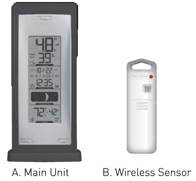
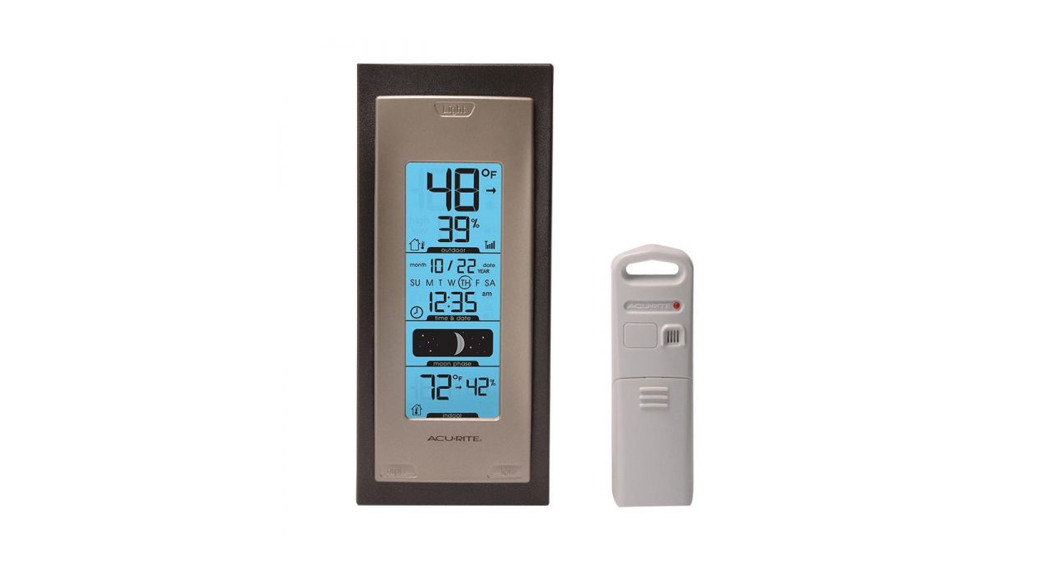
Package Contents:
[1 I Main Unit [A)[1 I Wireless Sensor [Bl[1) Hardware Bag[1 I Instruction ManualWhat You Need:• [5) AA batteriesThank You for purchasing this ACURITE® product. Please read this manual in it’s entirety to fully enjoy the benefits and features of this product. Please keep this manual for future reference.NOTE: A clear film is applied to the LCD at the factory that must be removed prior to using this product. Locate the clear tab on the left side of the display and simply peel to remove it.
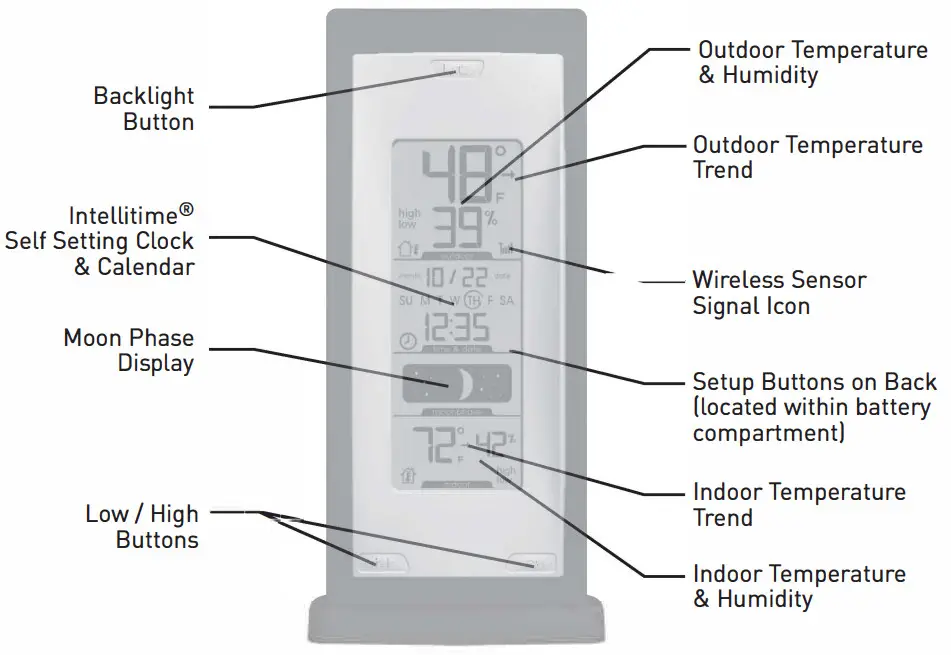
OVERVIEW OF FEATURES
SETUP
Battery Choice & Temperature RangeExtended periods of cold temperatures I below -4°F / -20°C I can cause alkaline batteries to function improperly. This will cause the outdoor wireless sensor to stop transmitting temperature readings. Use lithium batteries in these low-temperature conditions to ensure continued operation for wireless sensors placed outdoors. NOTE: rechargeable batteries are not recommended due to higher operating voltages.
 PLEASE DISPOSE OF OLD OR DEFECTIVE BATTERIES IN AN ENVIRONMENTALLY SAFE WAY AND IN ACCORDANCE WITH YOUR LOCAL LAWS AND REGULATIONS.BATTERY SAFETY: Follow the polarity(+/·) diagram in the battery compartment. Promptly remove dead batteries from the device. Dispose of used batteries properly. Only batteries of the same or equivalent type as recommended are to be used. DO NOT incinerate used batteries. DO NOT dispose of batteries in fire, as batteries may explode or leak. O NOT mix old and new batteries or types of batteries (alkaline/standard). DO NOT use rechargeable DO NOT batteries. recharge non-rechargeable DO NOT batteries. short-circuit the supply terminals.
A/B/C Wireless Identity Selection
To allow for more than one main unit and wireless sensor network to be used in close proximity, the main unit and the wireless sensor have a small switch labeled “A B C” within the battery compartments. This switch selects one of 3 wireless identities to use, and both switches MUST be set in matching positions (either A, B, or C) for wireless communication to take place successfully.
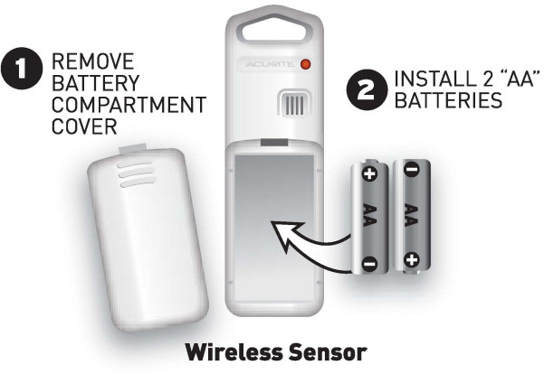
Install Batteries
Wireless SensorRemove the battery compartment cover. Install 2 fresh “AA” batteries as shown here.
Install Batteries
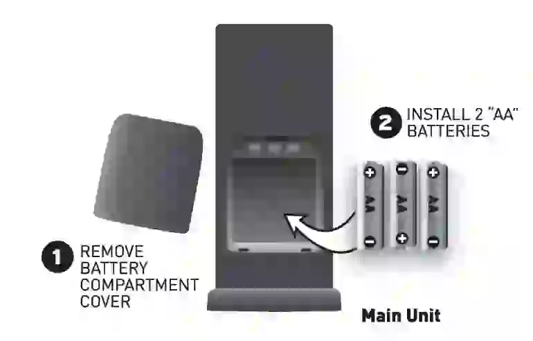
Main UnitRemove the battery compartment cover and install 3 fresh “AA” batteries as shown here.
 About the Set and Forget ClockYour new wireless thermometer is equipped with lntellitime® technology which is pre-programmed with the correct time and date. lntellitime® technology instructs the clock to self-set itself once batteries are installed. All you need to do is select your Time Zone and Daylight Saving Time preferences. The clock will automatically set itself and change automatically for Daylight Saving Time.Main Unit: Time and Date SetPress and hold the “SET” button (located on the back of the main unit in the battery compartment) for 3 seconds to enter into SET MODE. Once in set mode, the preference you are currently setting will blink on the display.
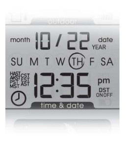 The preference set order is as follows:TIME ZONEDAYLIGHT SAVING TIME OBSERVANCE (on or off)CLOCK HOUR (note AM and PM indicators)CLOCK MINUTEMONTHDATEYEARTEMPERATURE UNITS (°For °CJTo adjust the currently selected (flashing! preference item, press the ”
 ![]() or
or ![]() buttons in the battery compartment to adjust up or down to the desired setting (press and HOLD to fast adjust!. To save your adjustments, press the “SET” button again to move on to adjusting the next preference.You will automatically exit TIME/DATE SET ODE f there is no button activity for 30 seconds. You may enter basic setup mode again at any time by pressing and holding the “SET” button.
buttons in the battery compartment to adjust up or down to the desired setting (press and HOLD to fast adjust!. To save your adjustments, press the “SET” button again to move on to adjusting the next preference.You will automatically exit TIME/DATE SET ODE f there is no button activity for 30 seconds. You may enter basic setup mode again at any time by pressing and holding the “SET” button.
PLACEMENT
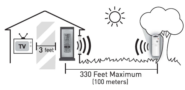
Now that setup is complete, you must choose a location to place the wireless sensor and the main unit. The wireless sensor MUST be placed less than 330 feet 1100 ml away from the main unit.This wireless thermometer uses radiofrequency for communication, which is susceptible to interference from other electronic devices and large metallic items or thick walls. Always place both units at least 3 feet l.91 ml away from appliances ITV, microwave, radios, etc. I or objects I large metal surfaces, thick stone walls, etc. I that may interfere with wireless communication.
 Placement of Main UnitPlace the main unit in a dry area free of dirt and dust. To help ensure n accurate indoor temperature and humidity measurement, be sure to place the main unit out of direct sunlight, and away from any heat ources or vents in your home. There are 2 placement options for the main unit. It can be hung on a wall using the integrated hang hole orplaced on a tabletop or other flat surface using the detachable stand.
 Placement of SensorThe wireless sensor MUST BE PLACED OUTDOORS to observe outdoor temperature and humidity. The wireless sensor must be placed less than 330 feet [100 ml from the main unit.The wireless sensor is water-resistant and is designed for general outdoor use. However, to extend the life of the product, place the wireless sensor in an area protected from direct weather elements. To ensure an accurate outdoor temperature measurement, be sure the wireless sensor is placed out of direct sunlight and away from any heat sources.There are 2 placement options for the wireless sensor. You may hang it on a wall using one of the two integrated hang holes, or use string [not included] to hang it from a suitable location like a well-covered tree branch.
OPERATION
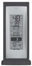
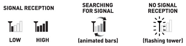
After the main unit and the wireless sensor are both powered on and wirelessly synchronized, no further input is required.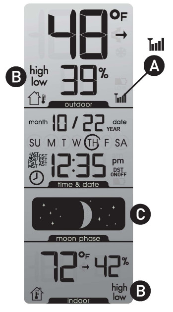 A. WIRELESS SIGNAL RECEPTION ICONThe main unit has a signal reception icon near the outdoor temperature display area. If there are a low number of “bars” present, you may experience no temperature display I .__. I or accuracy. In either case, you may need to relocate one or both of the units. If most or all 4 of the bars are present, wireless reception is good and no action is required. If you are experiencing reception issues, refer to the troubleshooting section.
 B. DAILY LOW/HIGH-TEMPERATURE MEMORY DISPLAYPress the LOW or HIGH button once to view the LOWEST or HIGHEST ecorded values for temperature and humidity. While viewing the LOWEST or HIGHEST recorded value, press and hold the “LOW or HIGH button for 2 seconds to manually clear the currently displayed recorded values. The LOW and HIGH recorded values will automatically clear and reset at 12:00 am [midnight] every day.C. MOON PHASEThis weather station features a moon phase window that will automatically display the current moon phase, provided the calendar is set
Troubleshooting
| Problem Possible Solutions | |
LOW Wireless Sensor Reception low bars low bars |
NOTE: It may take up to 20 minutes for the main unit to re-synchronize with the sensor when batteries are replaced.Make certain both units are within 330 feet Imo ml of each other.Make sure both units are placed at least 3 feet (.91 ml from other electronicappliances and devices that may interfere with the wireless communication (such as TVs, microwaves, computers excl.Use lithium batteries in the outdoor sensor when the temperature is below -4°F (-20°C). |
NO Wireless Sensor Reception no bars and flashing antenna icon no bars and flashing antenna icon |
Make certain both units are within 330 feet (WO ml of each other.The wireless ID setting on each unit must match for all units to communicate properly. See “Set Wireless ID” on the next page.There may be interference, try relocating each unit for better reception.The batteries may need to be replaced. |
| Main Unit Display Not Working | Make certain that the batteries are installed correctly and that they are contacting the terminals. Make certain all contacts are clean.The batteries may need to be replaced. |

Set Wireless ID
This wireless thermometer uses a long-range 433mhz radio frequency for communication.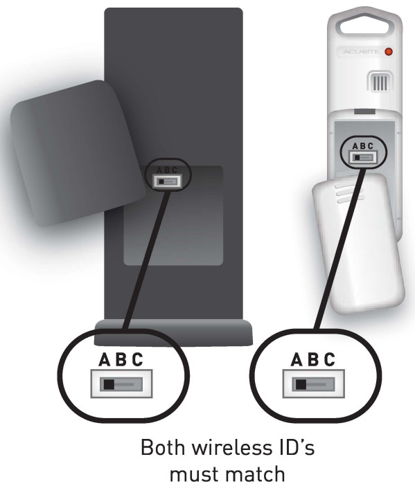 In the event that you have reception problems due to interference from another sensor network nearby, both the main unit and the wireless sensor have a selectable wireless ID. The ID switches are located within the battery compartments of the main unit and the wireless sensor.You may choose A.B or C; but both the main units and the wireless sensors IDs must match for successful synchronization.
PRODUCT SPECIFICATIONS
Measurement RangesTemperatureMain Unit [indoor): 32°F to 122°F / o°C to 50°CWireless Sensor [outdoor): -40°F to 158°F / -40°C to 70°CUse lithium batteries in the outdoor sensor when the temperature is below -4°F [-20°C).HumidityMain Unit [indoor): 20% to 95% relative humidity [operating temp. 32°F to 122°F/ o°C to 50°C lWireless Sensor [outdoor): 20% to 95% relative humiditysensor operating temp. 32°F to 122°F/ o°C to 50°C lNOTE: As with all humidity sensors, accuracy diminishes substantially when the temperature is below 32°F [o°C).
Specifications
Power RequirementsMain Unit: 3 x “AA” alkaline batteriesWireless Sensor: 2 x “AA” alkaline or lithium batteriesWireless CommunicationRadio Frequency: 433 MHzTransmission Intervals: every 16 seconds
 Please DO NOT return the product to the retail store.For technical assistance and product return information, please callCustomer Care: 877-221-1252 Mon. – Fri. 8:00 A.M. to 4:45 P.M. [CST)www.chaneyinstrument.com
LIMITED ONE YEAR WARRANTYChaney Instrument Company warrants that all products it manufactures be of good material and workmanship and to be free of defects if properly installed and operated for a period of one year from the date of purchase. REMEDY FOR BREACH OF THIS WARRANTY IS EXPRESSLY LIMITED TO REPAIR OR REPLACEMENT OF DEFECTIVE ITEMS. Any product which, under normal use and service, is proven to breach the warranty contained here n within ONE YEAR from the date of sale will, upon examination by Chaney, and at its sole option, be repaired or replaced by Chaney. In all cases, transportation costs and charges for returned goods shall be paid for by the purchaser. Chaney hereby disclaims all responsibility for such transportation costs and charges. This warranty will not be breached, and Chaney will give no credit for products it manufactures which shall have received normal wear and tear, been damaged, tampered, abused, improperly installed, damaged in shipping, or repaired or altered by others thanauthorized representatives of Chaney.THE ABOVE-DESCRIBED WARRANTY IS EXPRESSLY IN LIEU OF ALL OTHER WARRANTIES, EXPRESS OR IMPLIED, AND ALL OTHER WARRANTIES ARE HEREBY EXPRESSLY DISCLAIMED, INCLUDING WITHOUT LIMITATION THE IMPLIED WARRANTY OF MERCHANTABILITY AND THE IMPLIED WARRANTY OF FITNESS FOR A PARTICULAR PURPOSE. CHANEY EXPRESSLY DISCLAIMS ALL LIABILITY FOR SPECIAL, CONSEQUENTIAL, OR INCIDENTAL DAMAGES, WHETHER ARISING IN TORT OR BY CONTRACT FROM ANY BREACH OF THIS WARRANTY. SOME STATES DO NOT ALLOW THE EXCLUSION OR LIMITATION OF INCIDENTAL OR CONSEQUENTIAL DAMAGES, SO THE ABOVE LIMITATION OR EXCLUSION MAY NOT APPLY O YOU. CHANEY FURTHER DISCLAIMS ALL LIABILITY FROM PERSONAL INJURY RELATING TO ITS PRODUCTS TO THE EXTENT PERMITTED BY LAW. BY ACCEPTANCE OF ANY OF CHANEY”S EQUIPMENT OR PRODUCTS, THE PURCHASER ASSUMES ALL LIABILITY FOR THE ONSEQUENCES ARISING FROM THEIR USE OR MISUSE. NO PERSON, FIRM, OR CORPORATION IS AUTHORIZED TO ASSUME FOR CHANEY ANY OTHER LIABILITY IN CONNECTION WITH THE SALE OF ITS PRODUCTS. FURTHERMORE, NO PERSON, FIRM, OR CORPORATION IS AUTHORIZED TO MODIFY OR WAIVE THE TERMS OF THIS PARAGRAPH, AND THE PRECEDING PARAGRAPH, UNLESS DONE IN WRITING AND SIGNED BY A DULY AUTHORIZED AGENT OF CHANEY. THIS WARRANTY GIVES YOU SPECIFIC LEGAL RIGHTS, AND YOU MAY ALSO HAVE OTHER RIGHTS WHICH VARY FROM STATE TO STATE.
For in-warranty repair, please contact:Customer Care DepartmentChaney Instrument Company965 Wells StreetLake Geneva, WI 53147Chaney Customer Care877-221-1252Mon-Fri 8:00 a.m. to 4:45 p.m. CSTwww.chaneyinstrument.com

This device complies with part 15 of the FCC rules. Operation is subject to the following_ two conditions:
- This device may NOT cause harmful interference, and
- This device must accept any interference received, including interference that may cause undesired operation.NOTE: This equipment has been tested and found to comply with the limits for a Class B digital device, pursuant to Part 15 of the FCC rules. These limits are designed to provide reasonable protection against harmful interference in a residential installation. This equipment generates, uses, and can radiate radio frequency energy and, if not installed and used in accordance with the instructions, may cause harmful interference to radio communications. However, there is no guarantee that interference will not occur in an articular installation. If this equipment does cause harmful interference to radio or television reception, which can be determined by turning the equipment off and on, the user s encouraged to try to correct the interference by one or more of the following measures:
- Reorient or relocate the receiving antenna.
- Increase the separation between the equipment and the receiver.
- Connect the equipment into an outlet on a circuit different from that to which the receiver is connected.
- Consult the dealer or an experienced radio/TV technician for help.
NOTE: The manufacturer is not responsible for any radio or TV interference caused by unauthorized modifications to this equipment. Such modifications could void the user’s authority to operate the equipment.Patent numbers: 5,978,738; 6,076,044; 6,597,990
References
[xyz-ips snippet=”download-snippet”]