![]()
AcuRite 00608BPDI Weather Center Instruction Manual
Model: 00607 / 00608BPDI
It’s More than Accurate, it’s ![]() AcuRite offers an extensive assortment of precision instruments, designed to provide you with information you can depend on to Plan your day with confidence™.
AcuRite offers an extensive assortment of precision instruments, designed to provide you with information you can depend on to Plan your day with confidence™.
Questions? Contact Customer Support at (877) 221-1252 or visit www.AcuRite.com.
©Chaney Instrument Co. All rights reserved. AcuRite is a registered trademark of the Chaney Instrument Co., Lake Geneva, WI 53147. All other trademarks and copyrights are the property of their respective owners. AcuRite uses patented technology. Visit www.AcuRite.com/patents for details.
Printed in China00608PDI INST 020514
SAVE THIS MANUAL FOR FUTURE REFERENCE.
Congratulations on your new AcuRite product. To ensure the bestpossible product performance, please read this manual in its entiretyand retain it for future reference.
Unpacking Instructions
Remove the protective film that is applied to the LCD screen prior to using this product. Locate the tab and peel off to remove.
Package Contents
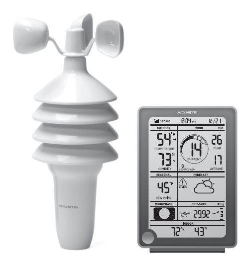
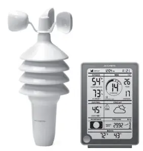
- Display unit with tabletop stand
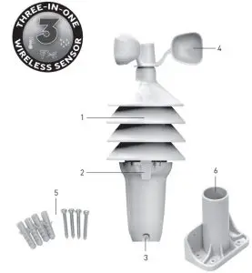
- 3-in-1 sensor
- Sensor mounting bracket
- Mounting hardware
- Instruction Manual
IMPORTANT
PRODUCT MUST BE REGISTERED TO RECEIVE WARRANTY SERVICE
PRODUCT REGISTRATIONRegister online to receive 1-year warranty protection

Features & Benefits
Display Unit
Customer Support
AcuRite customer support is committed to providing you with best-in-class service. For assistance, please have the model number of this product available and contact us in any of the following ways:
Phone: (877) 221-1252
Mail:
24/7 support at www.AcuRite.com
- Installation Videos
- Instruction Manuals
- Replacement Parts
- Register your Product
- Support User Forum
- Submit Feedback & Ideas
IMPORTANT
PRODUCT MUST BE REGISTERED TO RECEIVE WARRANTY SERVICE
PRODUCT REGISTRATION
Register online to receive 1-year warranty protection

Limited One Year Warranty
At AcuRite, we proudly uphold our commitment to quality technology. Chaney Instrument Co. warrants that all products it manufactures to be of good material and workmanship, and to be free of defects when properly installed and operated for a period of one year from the date of purchase.
We recommend that you visit us at www.AcuRite.com for the fastest way to register your product. However, product registration does not eliminate the need to retain your original proof of purchase in order to obtain warranty benefits.
Chaney Instrument Co. warrants that all products it manufactures to be of good material and workmanship, and to be free of defects when properly installed and operated for a period of one year from the date of purchase. Remedy for breach of this warranty is limited to repair or replacement of the defective item(s). Any product which, under normal use and service, is proven to breach the warranty contained herein within ONE YEAR from date of sale will, upon examination by Chaney, and at its sole option, be repaired or replaced by Chaney. Transportation costs and charges for returned goods shall be paid for by the purchaser. Chaney hereby disclaims all responsibility for such transportation costs and charges. This warranty will not be breached, and Chaney will give no credit for products it manufactures which have received normal wear and tear, been damaged (including by acts of nature), tampered, abused, improperly installed, damaged in shipping, or repaired or altered by others than authorized representatives of Chaney.
The above-described warranty is expressly in lieu of all other warranties, express or implied, and all other warranties are hereby expressly disclaimed, including without limitation the implied warranty of merchantability and the implied warranty of fitness for a particular purpose. Chaney expressly disclaims all liability for special, consequential or incidental damages, whether arising in tort or by contract from any breach of this warranty. Some states do not allow the exclusion or limitation of incidental or consequential damages, so the above limitation or exclusion may not apply to you. Chaney further disclaims all liability from personal injury relating to its products to the extent permitted by law. By acceptance of any of Chaney’s products, the purchaser assumes all liability for the consequences arising from their use or misuse. No person, firm or corporation is authorized to assume for Chaney any other liability in connection with the sale of its products. Furthermore, no person, firm or corporation is authorized to modify or waive the terms of this paragraph, and the preceding paragraph, unless done in writing and signed by a duly authorized agent of Chaney. This warranty gives you specific legal rights, and you may also have other rights which vary from state to state.
For in-warranty claims:Chaney Instrument Co. | 965 Wells St. | Lake Geneva, WI 53147
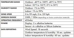
Specifications
FCC Information
This device complies with part 15 of FCC rules. Operation is subject to the following two conditions: 1- This device may NOT cause harmful interference, and 2- This device must accept any interference received, including interference that may cause undesired operation.
WARNING: Changes or modifications to this unit not expressly approved by the party responsible for compliance could void the user’s authority to operate the equipment.
NOTE: This equipment has been tested and found to comply with the limits for a Class B digital device, pursuant to Part 15 of the FCC rules. These limits are designed to provide reasonable protection against harmful interference in a residential installation.
This equipment generates, uses and can radiate radio frequency energy and, if not installed and used in accordance with the instructions, may cause harmful interference to radio communications.
However, there is no guarantee that interference will not occur in a particular installation. If this equipment does cause harmful interference to radio or television reception, which can be determined by turning the equipment off and on, the user is encouraged to try to correct the interference by one or more of the following measures:
- Reorient or relocate the receiving antenna.
- Increase the separation between the equipment and the receiver.
- Connect the equipment into an outlet on a circuit different from that to which the receiver is connected.
- Consult the dealer or an experienced radio/TV technician for help.
NOTE: The manufacturer is not responsible for any radio or TV interference caused by unauthorized modifications to this equipment. Such modifications could void the user authority to operate the equipment.
This device complies with Industry Canada licence-exempt RSS standard(s). Operation is subject to the following two confitions:
- This device may not cause interference, and
- This device must accept any interference received, including interference that may cause undesired operation of the device.
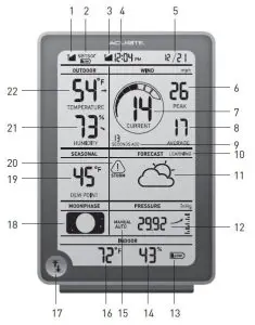
DISPLAY UNIT
- Wireless Sensor Signal Strength
- Low Sensor Battery Indicator
- Atomic Clock Signal Strength
- Atomic Clock: Maintains time with split-second accuracy and automatically updates for daylight saving time.
- Date
- Peak Wind SpeedHighest speed from past 60 minutes.
- Current Wind Speed
- Average Wind Speed: Based on all wind speed readings from the past 2 minutes.
- Time Stamp for Last Wind ReadingUpdates about every 18 seconds.
- Learning Mode Icon: Disappears after weather forecast self-calibration is complete.
- 12 to 24 Hour Weather Forecast: Self-Calibrating Forecasting pulls data from the outdoor sensor to generate your personal forecast.
- Barometric Pressure: Arrow icon indicates the direction the pressure is trending.
- Low Battery Indicator
- Current Indoor Humidity
- Auto or Manual Pressure ModeIndicates pressure mode preference.Auto Pressure ModePressure will self-calibrate over a 14 day Learning Mode.Manual Pressure ModeIndicates the pressure has been manually calibrated.
- Current Indoor Temperature
- Record Highs & Lows Button: View records for temperature and humidity.
- Moon Phase
- Seasonal Select: Wind chill will show when temperatures are below 40°F, Dewpoint when temperatures are between 41°F and 79°F and Heat Index when temperatures are above 80°F.
- Oncoming Storm Icon: Indicates a large, rapid pressure drop has been detected.
- Current Outdoor Humidity: Arrow icon indicates direction humidity is trending.
- Current Outdoor Temperature: Arrow icon indicates direction temperature is trending.Back of Display Unit
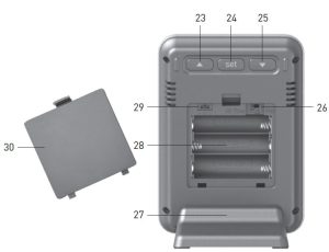
- “▲” Button for setup preferences.
- SET Buttonfor setup preferences.
- “▼” Button for setup preferences.
- Daily / All-Time Records Button Selects desired records to be viewed using Records Button (17).
- Removable Tabletop Stand
- Battery Compartment
- A-B-C SwitchID code that must match sensorʼs A-B-C switch to ensure units synchronize.
- Battery Compartment Cover
SETUP
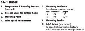
3-in-1 Sensor Setup
- Set the A-B-C SwitchThe A-B-C switch is located inside the battery compartment. It can be set to A, B or C. However, you must select the same letter choices for both the sensor and the display unit in order for the units to synchronize.
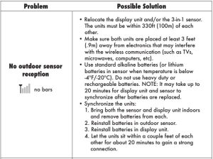
- Install or Replace Batteries Batteries MUST be installed for this product to operate. AcuRite recommends high quality alkaline or lithium batteries for the best product performance. Heavy duty or rechargeable batteries are not recommended.
The 3-in-1 sensor requires lithium batteries in low temperature conditions. Cold temperatures can cause alkaline batteries to function improperly. Use lithium batteries in the 3-in-1 sensor for temperatures below -4ºF / -20ºC.
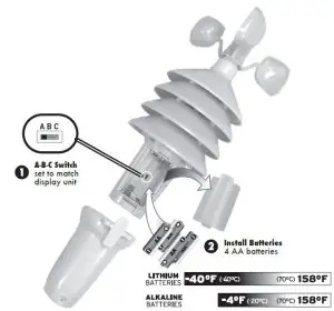
- Press the release lever and pull off the lower housing of the sensor.
- Remove the battery compartment cover. Take note of the A-B-C switch setting inside the battery compartment.
- Insert 4 x AA batteries into the battery compartment, as shown. Follow the polarity (+/-) diagram in the battery compartment.
- Replace the battery cover and lower housing of the sensor.
Calibration
Calibrate Temperature & HumidityThe indoor / outdoor temperature and humidity readings can be calibrated on the display unit to improve accuracy. Calibration can improve accuracy when 3-in-1 sensor placement or environmental factors impact your data accuracy.
- Locate the “▲ ”, “SET”, and “ ▼” buttons on the back of the display unit. Press AND HOLD all three buttons for at least 5 seconds.
- The temperature will begin flashing, indicating it is ready to be calibrated.
- Press the up or down arrow buttons to calibrate the data value higher or lower from the actual reading.
- Press the “SET” button to confirm the calibration adjustment. Note: The “
 ” icon remains illuminated next to calibrated values.
 - The next calibratable data will begin flashing, indicating it is ready to be calibrated. Repeat Steps 1 – 4 to calibrate additional data.
Calibrate Barometric PressureThe Weather Center default pressure mode is “AUTO”. In auto mode, the pressure will calibrate itself over a 14 day Learning Mode. Barometric pressure can be manually calibrated:
- Locate the “▲ ”, “SET”, and “▼ ” buttons on the back of the display unit.Press AND HOLD all three buttons for at least 5 seconds.
- Press the “SET” button to cycle through data until the pressure value beginsflashing.
- Press the “▲ ” or “ ▼” button to select “MANUAL” pressure mode.
- Press the “SET” button to confirm.
- Press the “▲ ” or “ ▼” buttons to calibrate the pressure value higher orlower from the self-calibrated reading.
- Press the “SET” button to confirm the calibration adjustment. Note: The “”icon remains illuminated next to the calibrated value.
Care & Maintenance
Display Unit CareClean with a soft, damp cloth. Do not use caustic cleaners or abrasives. Keep away from dust, dirt and moisture. Clean ventilation ports regularly with a gentle puff of air.
3-in-1 Sensor CareClean The Sensor
Clean with a soft damp cloth. Do not use caustic cleaners or abrasives.
Insect PreventionInsects may cause obstructions and interrupt data by nesting in or on the 3-in-1 sensor. To limit this problem, spray sensor with a household insect repellent. Consult the insect repellent instructions prior to use.
Snow & Freezing WeatherThe 3-in-1 sensor will not be damaged by freezing conditions.
Clean the Wind AnemometerRemove foreign matter from the outside of the sensor for free movement of the wind anemometer. If needed, use a small amount of clear silicone spray lubricant or graphite powder on the anemometer for improved movement.
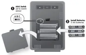
Display Unit Setup
- Set the A-B-C Switch Locate the A-B-C switch inside the battery compartment. Set the A-B-C switch to A, B or C. You must select the same letter choices for both the display unit and the sensor in order for the units to synchronize.
- Install or Replace Batteries
- Remove the battery compartment cover.
- Insert 3 x AA alkaline batteries into the battery compartment, as shown. Follow the polarity (+/-) diagram in the battery compartment.
- Replace the battery cover.
 PLEASE DISPOSE OF OLD OR DEFECTIVE BATTERIES IN AN ENVIRONMENTALLY SAFE WAY AND IN ACCORDANCE WITH YOUR LOCAL LAWS AND REGULATIONS.
BATTERY SAFETY: Clean the battery contacts and also those of the device prior to battery installation. Remove batteries from equipment which is not to be used for an extended period of time. Follow the polarity (+/-) diagram in the battery compartment. Promptly remove dead batteries from the device. Dispose of used batteries properly. Only batteries of the same or equivalent type as recommended are to be used. DO NOT incinerate used batteries. DO NOT dispose of batteries in fire, as batteries may explode or leak. DO NOT mix old and new batteries or types of batteries (alkaline/standard). DO NOT use rechargeable batteries. DO NOT recharge non-rechargeable batteries. DO NOT short-circuit the supply terminals.
Atomic ClockAcuRite atomic clocks use a radio-controlled signal to synchronize to the correct time broadcast by the National Institute of Standards and Technology (NIST) Radio Station WWVB, located near Fort Collins, Colorado. WWVB broadcasts the current time and date with split-second accuracy.
This AcuRite atomic clock will maintain itself to the correct time, and automatically adjust itself for daylight saving time to provide the most accurate timekeeping standard possible.
Please note: The atomic signal generally takes a few hours to synchronize, so it is important to manually set the time and date after powering on the display.
Set the Time, Date & UnitsThe clock and calendar are utilized to time stamp history records and other data, so it is important to set the time and date soon after you power on the display unit.
Press and HOLD the “SET” button to enter SET MODE. Once in set mode, the preference you are currently setting will blink on the display.
To adjust the currently selected (flashing) item, press and release the “ ▲” or “▼ ” buttons (press and HOLD to fast adjust).
To save your adjustments, press and release the “SET” button again to adjust the next preference. The preference set order is as follows
TIME ZONE (PST MST CST EST AST HAT [HAST] AKT [AKST])AUTO DST (Automatically adjust time -/+ on DST dates)*CLOCK HOURCLOCK MINUTECALENDAR MONTHCALENDAR DATECALENDAR YEARUNITS: TEMPERATURE (ºF or ºC)UNITS: PRESSURE (inHg or mb)UNITS: WIND SPEED (mph, kph, knots)
You will automatically exit SET MODE if no buttons are touched for 30 seconds. Enter basic setup mode at any time by pressing the “SET” button.
* If you live in an area that observes Daylight Saving Time, DST should be set to ON even if it is not currently Daylight Savings Time.
Troubleshooting
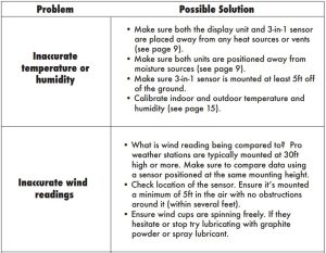
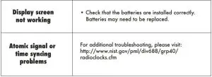
If your AcuRite product does not operate properly after trying the troubleshooting steps, visit www.AcuRite.com or call (877) 221-1252 for assistance.
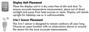
Placement for Maximum Accuracy
AcuRite sensors are sensitive to surrounding environmental conditions. Proper placement of both the display unit and the sensor are critical to the accuracy and performance of this product.
Important Placement Guidelines
Display unit and sensor must be within 330ft (100m) of each other.
MAXIMIZE WIRELESS RANGEPlace units away from large metallic items, thick walls, metal surfaces, or other objects that may limit wireless communication.
PREVENT WIRELESS INTERFERENCEPlace both units at least 3ft (.9m) away from electronic devices (TV, computer, microwave, radio, etc.).
LOCATE AWAY FROM HEAT SOURCESPosition sensor away from heaters, air conditioners, chimneys, exhaust vents, asphalt and concrete (surfaces that radiate heat).
LOCATE AWAY FROM HUMIDITY SOURCESAvoid installing the sensor near pools, spas, or other bodies of water. Water sources may impact humidity accuracy.
LOCATE AWAY FROM SPRINKLER HEADSDO NOT install the sensor where it will be sprayed by a sprinkler system. This may force water inside the sensor.
LOCATE AWAY FROM WIND OBSTRUCTIONSDO NOT mount the sensor with obstructions around it. Consider a location that is a wide open area, with few structures around to ensure accurate wind speed measurement
Visit us online to view installation photos and video, or learn more about AcuRite technology: www.AcuRite.com/3in1

OPERATION
3-in-1 Sensor Installation GuidelinesINSTALLATION HEIGHT Mount the sensor at least 5 feet (1.5 meters) off the ground (higher is better for wind measurement) in an open area. Secure to fence post, 2”x4“ wood, 3/4” pole, etc. (not included)
LEVEL INSTALLATION Use a bubble level (not included) to ensure level installation for accurate wind measurement.
Top or Side Mount

- Insert the mounting base into the hole on the bottom of the sensor.
- Use one of the screws included in the hardware bag to fasten the lower sensor housing to the mounting base.
- Make sure the sensor is level using a bubble level.
- Fasten mounting base to a post or railing using 2 screws.
Pole Mount
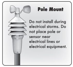
- Insert 3/4” schedule 40 PVC (25.8 mm O.D.) pole (not included) or similar item all the way into the hole on the bottom of the sensor. Note: Mounting base not used.
- Use one of the screws included in the hardware bag to fasten the lower sensor housing securely to the pole.
- Make sure the sensor is level using a bubble level.
The 3-in-1 sensor is now ready to use.
Basic Setup is CompleteThe 3-in-1 sensor will now synchronize with the display unit. It may take a few minutes for synchronization to complete. If both or one of the units appear to be functioning improperly, please refer to the troubleshooting section.
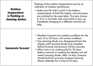
Using the Weather CenterLearning ModeSelf-Calibrating Forecasting use a unique algorithm to analyze changes in pressure and temperature over a time period (called Learning Mode) to determine your altitude. After 14 days, the Learning Mode icon disappears from the display screen. At this point, the self-calibrated pressure is tuned in to your location and the unit is ready for superior weather prediction.
Weather ForecastAcuRiteʼs patented Self-Calibrating Forecasting provides your personal forecast of weather conditions for the next 12 to 24 hours by collecting data from the sensor in your backyard. It generates a forecast with pinpoint accuracy – personalized for your exact location.
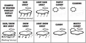
View the complete list of icons at www.AcuRite.com/acurite-icons
Barometric PressureSubtle variations in barometric pressure greatly affect the weather. This weather center displays the current pressure with an arrow icon to indicate the direction the pressure is trending (FALLING, STEADY, or RISING).
High & Low RecordsThe Record Highs & Lows button ( ![]() ) displays minimum and maximum recordings for outdoor and indoor temperature and humidity. To select between viewing daily (since midnight) or all-time records, slide the switch located on the back of the display. To reset low records, press and hold the (▼) button while viewing low records. To reset high records, press and hold the (▲) button while viewing high
) displays minimum and maximum recordings for outdoor and indoor temperature and humidity. To select between viewing daily (since midnight) or all-time records, slide the switch located on the back of the display. To reset low records, press and hold the (▼) button while viewing low records. To reset high records, press and hold the (▲) button while viewing high
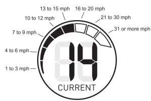
Wind SpeedThe Wind area of the display features WIND SPEED PEAK, AVERAGE, CURRENT WIND SPEED, and a graphic representation of current wind speed.
There is also a time stamp for the last wind speed reading.
References
[xyz-ips snippet=”download-snippet”]