
INST – 00612 040507
![]()
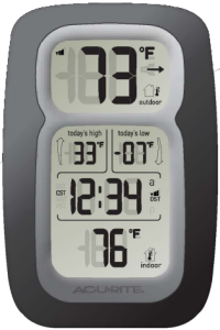
Wireless WeatherThermometerwith atomic clock#00612

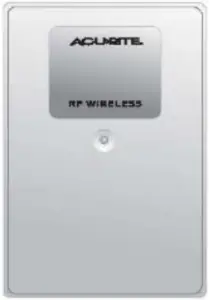
A. Main Unit B. Wireless Sensor
Instruction Manual
Package Contents :[1] Main Unit [A] with stand[1] Wireless Sensor [B][1] Hardware Bag[1] Instruction Manual
What You Need :• Philips Screwdriver• [5] AA batteries-see “Install Batteries” on page 2
Thank You for purchasing this ACURITE® product. This wireless thermometer features outdoor temperature, outdoor temperature memory (daily high/low), indoor temperature and an atomic clock. Please read this manual in it’s entirety to fully enjoy the benefits and features of this product. Please keep this manual for future reference.
NOTE: A clear film is applied to the LCD at the factory that must be removed prior to using this product. Locate the clear tab and simply peel to remove.
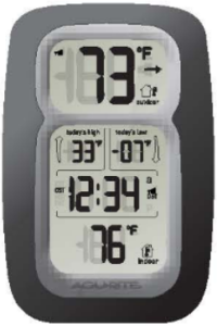
1 · OVERVIEW OF FEATURES
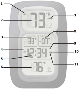
- Wireless Signal Reception Indicator
- Outdoor Temperature
- Outdoor Temp. Daily High
- Time Zone
- Atomic Clock
- Indoor Temperature
- Outdoor Temp. Trend Indicator
- Outdoor Temp. Daily Low
- AM/PM Indicator
- Clock Signal Reception Icon
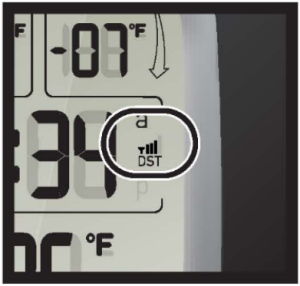
- Daylight Saving Time [DST] indicator
About the Atomic Clock
A clock is considered atomic if it has an accuracy of one second in a million years. Consumer clocks are considered atomic if they attain this accuracy by receiving a signal from an atomic clock. In North America, the National Institute of Standards and Technologies operates an atomic clock in Colorado which transmits the time codes via the the radio station WWVB . The signal is transmitted in a very low frequency [60,000 Hz]. The Acurite clock you have purchased includes a built-in receiver which picks up the signal from the WWVB station . NOTE: Due to solar radiation in the atmosphere, the atomic clock signal is weak during the day. Most synchronization with the WWVB atomic clock signal happens at night when there is less interference.
2 · SETUP
 Install Batteries
 Install Batteries
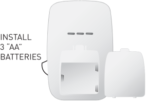
NOTE: Install all batteries in both units within a 6 minute period to ensure proper wireless functionality.
A. Wireless Sensor1] Remove the 4 battery compartment screws.2] Remove the battery compartment cover and install 2 fresh ‘”AA” batteries as shown here.
 Always install batteries into the wireless sensor FIRST to ensure proper wireless synchronization with the main unit.
B. Main UnitRemove the battery compartment cover and install 3 fresh “AA” batteries as shown here.
Operating Range of Batteries

Extended periods of cold temperatures ( below -4°F / -20°c ) can cause alkaline batteries to function improperly. This will cause the outdoor wireless sensor to stop transmitting temperature readings. Use lithium batteries in these low temperature conditions to ensure continued operation for wireless sensors placed outdoors.
 PLEASE DISPOSE OF OLD OR DEFECTIVE BATTERIES IN AN ENVIRONMENTALLY SAFE WAY AND IN ACCORDANCE WITH YOUR LOCAL LAWS AND REGULATIONS.
BATTERY SAFETY: Follow the polarity(+/-) diagram in the battery compartment. Promptly remove dead batteries from the device. Dispose of used batteries properly. Only batteries of the same or equivalent type as recommended are to be used. DO NOT incinerate used batteries. DO NOT dispose of batteries in fire, as batteries may explode or leak. DO NOT mix old and new batteries or types of batteries (alkaline/standard). DO NOT use rechargeable batteries. DO NOT recharge non-rechargeable batteries. DO NOT short-circuit the supply terminals.
Select Celsius [°C] or Fahrenheit [°F]

The main unit is capable of displaying the indoor and outdoor temperature readings in either °C or °F. To select either °C or °F, slide the switch located within the battery compartment to the desired measurement unit.
Main Unit : Basic Setup
After installing batteries and selecting °F or °C, the time zone, time, and DST [daylight saving time] must be set initially. After the initial manual setting, the atomic clock will maintain it’s accuracy and adjust for DST automatically.
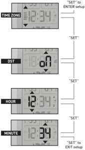 When first entering basic setup mode, the time zone will be flashing [default is PST]. Adjust the time zone using the “
![]() ” or “
” or “![]() ” buttons on the back of the main unit, then press the “SET” button to confirm your time zone selection and move on.
” buttons on the back of the main unit, then press the “SET” button to confirm your time zone selection and move on.
Now select DST [daylight saving time] “on” or “off’ by pressing the “![]() ” or “
” or “![]() ” buttons on the back of the main unit. Press the “SET” button to confirm your DST selection.
” buttons on the back of the main unit. Press the “SET” button to confirm your DST selection.
Next, adjust the HOUR by pressing the “![]() ” or “
” or “![]() ” buttons on the back of the main unit. Press the “SET” button to confirm your HOUR selection and to move on to MINUTE setting . Again, adjust the MINUTE by pressing the “
” buttons on the back of the main unit. Press the “SET” button to confirm your HOUR selection and to move on to MINUTE setting . Again, adjust the MINUTE by pressing the “![]() ” or “
” or “![]() ” buttons. You may press and HOLD the “
” buttons. You may press and HOLD the “![]() ” or “
” or “![]() ” to adjust the minutes at a faster rate .
” to adjust the minutes at a faster rate .
Press the “SET” button one more time to exit basic setup mode. You may enter basic setup mode at any time by pressing the “SET” button .
Basic Setup is Now Complete
The wireless sensor will soon send a signal to the main unit and the two units will be synchronized . It may take a few minutes for synchronization to be complete. If both or one of the units appear to be functioning improperly, refer to the troubleshooting section in this manual.
3 · PLACEMENT
Now that setup is complete, you must choose a location to place the wireless sensor and the main unit. The wireless sensor MUST be placed less than 100 feet away from the main unit.
This wireless thermometer uses radio frequency for communication , which is susceptible to interference from other electronic devices and large metallic items or thick walls. Always place both units at least 3 feet away from appliances I TV, microwave, radios, etc. I or objects I large metal surfaces, thick stone walls, etc. I that may interfere with the wireless communication.

Placement of Main Unit
 Placement of Main Unit
Place the main unit in a dry area free of dirt and dust. To help ensure an accurate indoor temperature measurement, be sure to place the main unit out of direct sunlight, and away from any heat sources or vents in your home .
There are 2 placement options for the the main unit. You may hang the main unit on a wall using the integrated hang hole on the back. Alternatively, you may use the detachable “table stand” to place the main unit on a table top or other flat surface .
Placement of Sensor
 Placement of Sensor
The wireless sensor MUST BE PLACED OUTDOORS to observe outdoor temperatures and relay the outdoor temperature to the main unit display. The wireless sensor must be placed less than 100 feet from the main unit.
The wireless sensor is water resistant and is designed for outdoor use. However, to extend the life of the product, place the wireless sensor in an area protected from direct weather elements. To ensure an accurate outdoor temperature measurement, be sure the wireless sensor is placed out of direct sunlight and away from any heat sources .
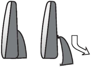
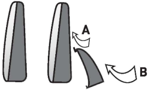
Main Unit Detachable Stand
Included with the main unit is a detachable stand for table top placement.
Remove Attach
![]()
Wireless Reception
The main unit has a wireless signal reception icon in the temperature display area and in the clock display area . If there are a low number of “bars” present, you may experience no temperature display (“–“) or clock inaccuracy.In either case, you may need to relocate one or both of the units. If most or all 4 of the bars are present, wireless reception is good and no action is required.

temperature time
![]()
4 · OPERATION
After the main unit and the wireless sensor are both powered on and wirelessly synchronized, no further input is required . The atomic clock will automatically re-synchronize occasionally to ensure the clock is accurate.

- Wireless Signal Reception Indicator
- Outdoor Temperature
- Time Zone
- Atomic Clock
- Atomic Clock Signal Reception Indicator
- Indoor Temperature
- Outdoor Temperature Trend IndicatorThe trend indicator compares the last 10 minutes temperature with the previous hour average. This reading will provide a direction of where the temperature is heading [rising, decreasing or staying the same].
- Outdoor Temp. Daily high/LowThis feature gives you the recorded highest & lowest temperatures since 12:00 am (midnight).
Batteries should last approximately one year under normal conditions. When the batteries need replacement, follow the battery installation procedure outlined in this manual exactly to ensure proper operation .
Troubleshooting
|
Problem |
Possible Solution |
|
Bad Temperature Reception no bars |
Relocate the main unit and/or the wireless sensor. Both units must be within 100 feet from each other. Make sure both units are placed at least 3 feet from other electronic appliances and devices that may interfere with the wireless communication [such as TVs, microwaves, computers etc]. NOTE : It may take up to 20 minutes for the main unit to resynchronize with the sensor when batteries are replaced. |
|
Bad Atomic Clock Reception
no bars |
Relocate the main unit. Make sure the main unit is placed at least 3 feet from other electronic appliances and devices that may interfere with the wireless communication [such as TVs, microwaves , computers etc].Large metallic surfaces will also interfere with the atomic clock signal. |
|
No Outdoor Temperature or Humidity Display (no communication] |
If wireless reception is bad [no bars]. see “Bad Reception” section above. The wireless ID setting on each unit must match for both units to communicate properly. See “Set Wireless 10” on the next page. |
|
Main Unit Display Not Working |
Make certain that the batteries are installed correctly. The batteries may need replacing. |

Set Wireless ID
both wireless ID’s must match
This wireless thermometer uses long range 433mhz radio frequency for communication .
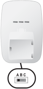
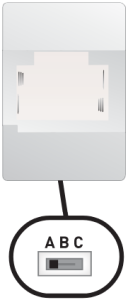
In the event that you have reception problems due to interference, both the main unit and the wireless sensor have a selectable wireless ID . The ID switches are located within the battery compartments of the main unit and the wireless sensor.
You may choose A, B or C; but both the main units and the wireless sensors IDs must match for successful synchronization .
5 · PRODUCT SPECIFICATIONS
Measurement Ranges
TemperatureMain Unit: 32°F to 122°F / 0°C to 50°CWireless Sensor: -40°F to 158°F / -40°C to 70°C
Specifications
Power RequirementsMain Unit: 3 x “AA” alkaline or lithium batteriesWireless Sensor: 2 x “AA” alkaline or lithium batteries
Wireless CommunicationRadio Frequency: 433 mhzTransmission Intervals : every 16 seconds
Atomic ClockFrequency: WWVB 60KhzSynchronizes Daily
 Please DO NOT return product to the retail store.For technical assistance and product return information, please callCustomer Care : 877-221-1252 Mon. – Fri. 8:00 A.M. to 4:45 P.M. [CST]
www.chaneyinstrument.com
LIMITED ONE YEAR WARRANTYChaney Instrument Company warrants that all products it manufactures to be of good material and workmanship and to be free of defects if properly installed and operated for a period of one year from date of purchase. REMEDY FOR BREACH OF THIS WARRANTY IS EXPRESSLY LIMITED TO REPAIR OR REPLACEMENT OF DEFECTIVE ITEMS. Any product which, under normal use and service, is proven to breach the warranty contained herein within ONE YEAR from date of sale will, upon examination by Chaney, and at its sole option, be repaired or replaced by Chaney. In all cases, transportation costs and charges for returned goods shall be paid for by the purchaser. Chaney hereby disclaims all responsibility for such transportation costs and charges. This warranty will not be breached, and Chaney will give no credit for products it manufactures which shall have received normal wear and tear, been damaged, tampered, abused, improperly installed, damaged in shipping, or repaired or altered by others than authorized representatives of Chaney.
THE ABOVE-DESCRIBED WARRANTY IS EXPRESSLY IN LIEU OF ALL OTHER WARRANTIES, EXPRESS OR IMPLIED, AND ALL OTHER WARRANTIES ARE HEREBY EXPRESSLY DISCLAIMED, INCLUDING WITHOUT LIMITATION THE IMPLIED WARRANTY OF MERCHANTABILITY AND THE IMPLIED WARRANTY OF FITNESS FOR A PARTICULAR PURPOSE. CHANEY EXPRESSLY DISCLAIMS ALL LIABILITY FOR SPECIAL, CONSEQUENTIAL OR INCIDENTAL DAMAGES, WHETHER ARISING IN TORT OR BY CONTRACT FROM ANY BREACH OF THIS WARRANTY. SOME STATES DO NOT ALLOW THE EXCLUSION OR LIMITATION OF INCIDENTAL OR CONSEQUENTIAL DAMAGES, SO THE ABOVE LIMITATION OR EXCLUSION MAY NOT APPLY TO YOU. CHANEY FURTHER DISCLAIMS ALL LIABILITY FROM PERSONAL INJURY RELATING TO ITS PRODUCTS TO THE EXTENT PERMITTED BY LAW. BY ACCEPTANCE OF ANY OF CHANEY’S EQUIPMENT OR PRODUCTS, THE PURCHASER ASSUMES ALL LIABILITY FOR THE CONSEQUENCES ARISING FROM THEIR USE OR MISUSE. NO PERSON, FIRM OR CORPORATION IS AUTHORIZED TO ASSUME FOR CHANEY ANY OTHER LIABILITY IN CONNECTION WITH THE SALE OF ITS PRODUCTS. FURTHERMORE, NO PERSON, FIRM OR CORPORATION IS AUTHORIZED TO MODIFY OR WAIVE THE TERMS OF THIS PARAGRAPH, AND THE PRECEDING PARAGRAPH, UNLESS DONE IN WRITING AND SIGNED BY A DULY AUTHORIZED AGENT OF CHANEY. THIS WARRANTY GIVES YOU SPECIFIC LEGAL RIGHTS, AND YOU MAY ALSO HAVE OTHER RIGHTS WHICH VARY FROM STATE TO STATE.
For in-warranty repair, please contact:Customer Care Department Chaney Customer CareChaney Instrument Company 877-221-1252965 Wells Street Mon-Fri 8:00 a.m. to 4:45 p.m. CSTLake Geneva, WI 53147
 This device complies with part 15 of the FCC rules. Operation is subject to the following two conditions :1- This device may NOT cause harmful interference, and2- This device must accept any interference received, including interference that may cause undesired operation .
NOTE : This equipment has been tested and found to comply with the limits for a Class B digital device, pursuant to Part 15 of the FCC rules . These limits are designed to provide reasonable protection against harmful interference in a residential installation . This equipment generates, uses and can radiate radio frequency energy and, if not installed and used in accordance with the instructions, may cause harmful interference to radio communications.However, There is no guarantee that interference will not occur in a particular installation. If this equipment does cause harmful interference to radio or television reception, which can be determined by turning the equipment off and on, the user is encouraged to try to correct the interference by one or more of the following measures :
- Reorient or relocate the receiving antenna.
- Increase the separation between the equipment and the receiver.
- Connect the equipment into an outlet on a circuit different from that to which the receiver is connected.
- Consult the dealer or an experienced radio/TV technician for help.
NOTE : The manufacturer is not responsible for any radio or TV interference caused by unauthorized modifications to this equipment. Such modifications could void the user authority to operate the equipment.
Patent numbers: 5,978,738; 6,076,044; 6,597,990
![]()
Product Registration
To receive product information, registeryour product online. It’s quick and easy!Log on to http://www.chaneyinstrument.com/product_reg.htm
References
[xyz-ips snippet=”download-snippet”]