![]() DESIGNED TO WORK FOR YOUWireless Weather Station model #00634Instruction Manual
DESIGNED TO WORK FOR YOUWireless Weather Station model #00634Instruction Manual
Package Contents:
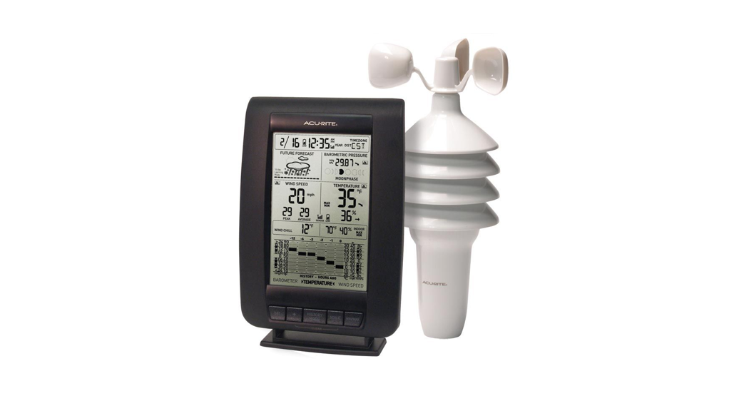
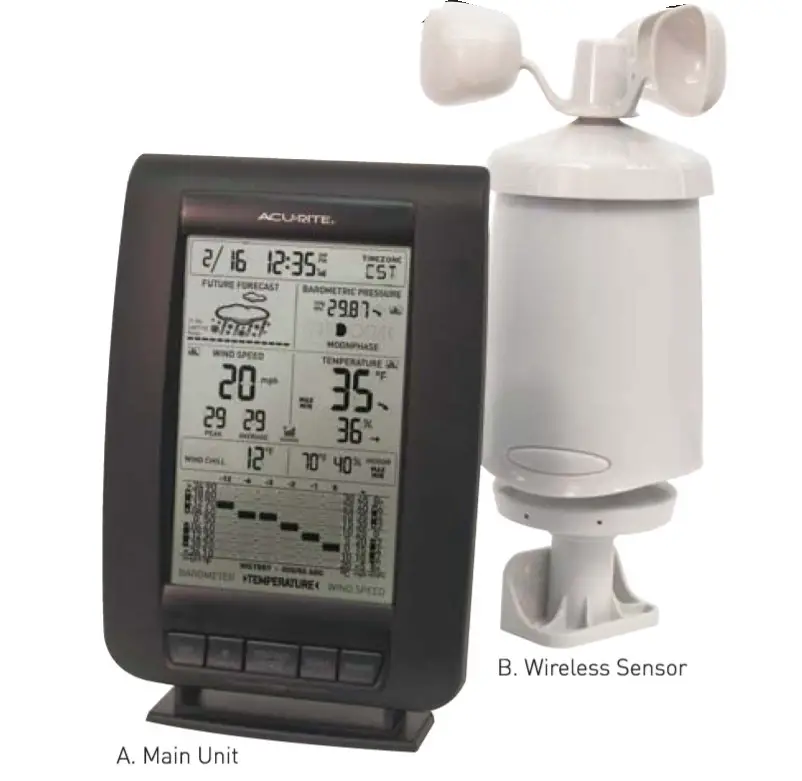
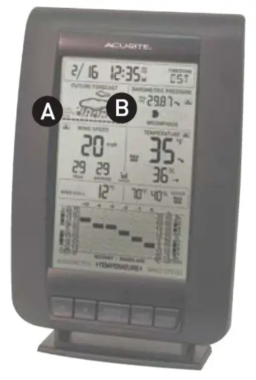
- Main Unit [A]with stand
- Wireless Sensor [B]with mounting bracket
What You Need:
- Small Phillips Screwdriver
- [7] AA batteries
Thank You for purchasing this ACURITE® product. Please read this manual in its entirety to fully enjoy the benefits and features of this product. Please keep this manual for future reference.NOTE: A clear film is applied to the LCD the factors that must be removed prior to using this product. Locate the clear tab and simply peel to remove.
SECTION 1 · OVERVIEW OF FEATURES
 |
WIRELESS SENSOR
|
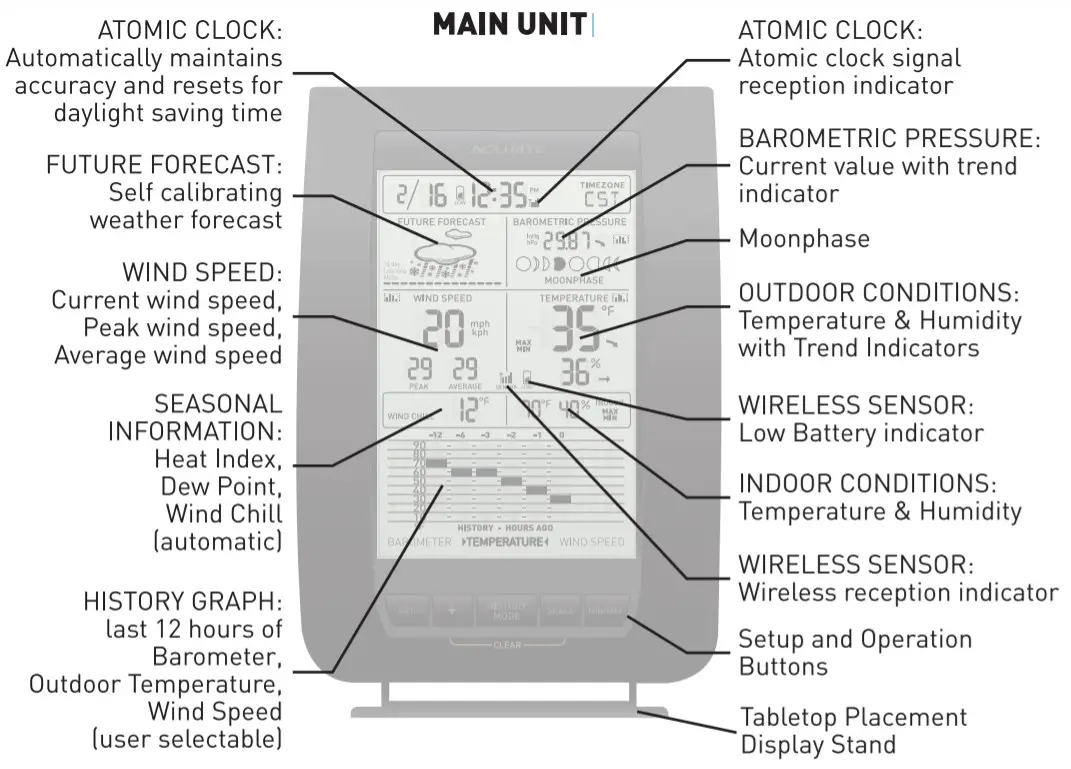
About the Atomic ClockA clock is considered atomic if it has an accuracy of one second in a million years.Consumer clocks are considered atomic if they attain this accuracy by receiving a signal from an atomic clock. In North America, the National Institute of Standards and Technologies operates an atomic clock in Colorado which transmits the time codes via the radio station WWVB.The Acurite clock you have purchased includes a built-in receiver that picks up the signal from the WWVB station. For the best possible reception, place the main unit with the backside facing Colorado.NOTE: Due to solar radiation in the atmosphere, the atomic clock signal is weaker during the day.Most synchronization with the WWVB atomic clock signal happens at night when there is less interference.About the Wireless SensorThis wireless weather station features a wireless sensor that provides wind, temperature, and humidity data and broadcasts this information to the main display unit. This wireless sensor will provide accurate outdoor weather conditions when placed properly. The wireless sensor contains sensitive electronic components and a balanced anemometer (for wind speed measurement). Care must be taken during setup and when considering placement to make certain the unit is not dropped or struck with any falling debris from trees or structures.
SECTION 2 · SETUP
A/8/C Wireless SelectionTo allow for more than one weather station and wireless sensor network to be used in close proximity, the main unit, and the wireless sensor has a small switch labeled “A B C” within the battery compartments.This switch selects one of 3 wireless Modesto use, and both switches must be set in matching positions(either A, B, or C) for wireless communication to take place successfully.Battery Choice & Temperature RangeExtended periods of cold temperatures (below -4°F / -20°C) I can cause alkaline batteries to function improperly. This will cause the outdoor wireless sensor to stop transmitting temperature readings. Use lithium batteries in these low-temperature conditions to ensure continued operation for wireless sensors placed outdoors.NOTE: Rechargeable batteries are not recommended due to higher operating voltages.
![]()
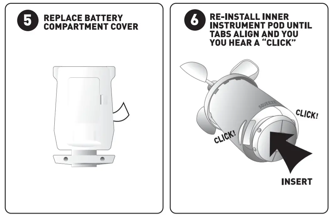
Install Batteries
NOTE: Install all batteries in both units within a 6 minute period to ensure proper wireless functionality.Always install batteries into the wireless sensor FIRST.Wireless Sensor – 4 “AA” Batteries Required (not included)
 |
 |
Install BatteriesNOTE: Install all batteries in both units within a 6 minute period to ensure proper wireless functionality.Always install batteries into the wireless sensor FIRST.Main Unit – 3 “AA” Batteries Required [notincludedl

PLEASE DISPOSE OF OLD OR DEFECTIVE BATTERIES IN AN ENVIRONMENTALLY SAFE WAY AND IN ACCORDANCE WITH YOUR LOCAL LAWS AND REGULATIONS.BATTERY SAFETY: Clean the battery contacts and also those of the device prior to the battery installation. Remove batteries from equipment that is not to be used for an extended period of time. Follow the polarity(+/-] diagram in the battery compartment. Promptly remove dead batteries from the device. Dispose of used batteries properly. Only batteries of the same or equivalent type as recommended are to be used. DO NOT incinerate used batteries. DO NOT dispose of batteries in fire, as batteries may explode or leak. DO NOT mix old and new batteries or types of batteries (alkaline/standard]. DO NOT use rechargeable batteries. DO NOT recharge non-rechargeable batteries. DO NOT short-circuit the supply terminals.
Main Unit: Basic Setup
After installing batteries, it is recommended that you set the clock and calendar initially. After the atomic clock signal is acquired, which may take up to 24 hours, the clock accuracy and daylight saving time changes will be automatically maintained.To set the clock and other preferences, press AND HOLD the “SET’ button for 5 seconds to enter into SET MODE. Once in set mode, the preference you are currently setting will blink on the display.To adjust the currently selected [flashing] preference item, press the”+” button [press and HOLD to fast adjust].To save your adjustments, press the “SET’ button again to move on to adjusting the next preference. The preference set order is as follows:TIME ZONE(PST MST CST EST)DST[Daylight Saving Time ON OR OFF)CLOCK HOURCLOCK MINUTEYEARCALENDAR MONTHCALENDAR YEARYou will automatically exit SET MODE if no buttons are depressed for 30 seconds.You may enter basic setup mode again at any time by pressing AND HOLDING the “SET’ button.Main Unit: Scale SelectionThe main unit is capable of displaying some values in an alternate scale mode.To switch between modes, press the “SCALE” button.SCALE MODE 1Temperature – °F [fahrenheit)Barometric Pressure- inHg [inches of mercury)Wind Speed/Peak/Average- mph [miles per hour)SCALE MODE 2Temperature – °C [Celsius)Barometric Pressure- hPa [Hectopascal)Wind Speed/Peak/Average- kph [kilometers per hour)NOTE: The “WIND SPEED” history mode chart will not change to the “kph” scale, it will remain to display ··mph” data.
Setup is Now CompleteThe wireless sensor will soon send a signal to the main unit and the two units will be synchronized. It may take a few minutes for synchronization to be complete. If both or one of the units appears to be functioning improperly, refer to the troubleshooting section in this manual.
SECTION 3 · OPERATION
A 14 Day Learning ModeThis weather station has a patented “fourteen-day learning mode” calibration process. During this learning mode, the weather station will make altitude calculations that may affect the accuracy of the forecast. Once the 14-day learning mode process is complete, the learning mode icon will disappear and the weather forecast should be ready for superior operation.14dayLearningMode —–B Future Forecast IconThe future forecast feature automatically gives you the predicted weather forecast icon for the next 12 to 24 hours based on an advanced algorithm that analyzes barometric pressure changes and temperature. This weather forecaster will provide the most accurate forecast that a single station instrument can provide.

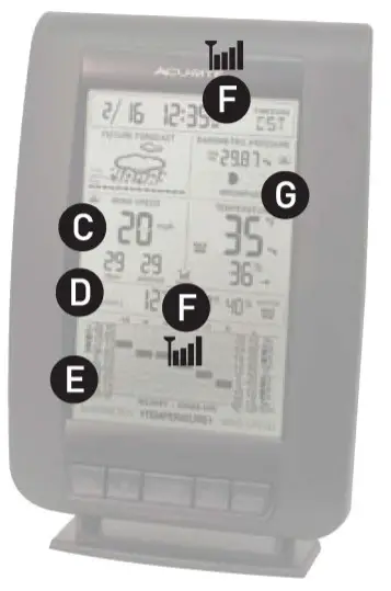
C Wind Speed Data WindowThis weather station features an advanced wind speed data window that provides the wind speed, the peak value, and the average value.WIND SPEED: most current wind speed reading, this value is updated every 18 seconds.PEAK: the highest wind speed reading recorded in the last hour.AVERAGE: the combined averaged wind speed readings from the last 2 minutes.NOTE: The wireless sensor must be placed outdoors to observe outdoor wind speed.D SeasonalWindow (wind chill/dew point/heat index)This weather station features a “Seasonal .. window which will automatically display the wind chill, the dew point, or the heat index information when it is relevant.

EHistory Mode GraphingThis weather station features a selectable history mode which will graph and display the changes for the last 12 hours [-12,-6,-3,-2,-1, O].There are 3 selectable weather categories; Barometer [barometric pressure).Temperature or Wind Speed. Press the “HISTORY MODE” button to alternate “M1.rn” through the 3 options. Note the graphing icon ![]() next to the currently selected data window.BAROMETER: hourly reading on the hour. TEMPERATURE: hourly [outdoor) the temperature reading on the hour. WIND SPEED: hourly wind speed AVERAGEreading.
next to the currently selected data window.BAROMETER: hourly reading on the hour. TEMPERATURE: hourly [outdoor) the temperature reading on the hour. WIND SPEED: hourly wind speed AVERAGEreading.FWireless Signal Reception Icons ![]() The main unit has a signal reception icon in the outdoor wind speed/ temperature display area. If most or all four of the bars are present, wireless reception is good and no action is required. If there are a low number of ··bars” present, you may experience wind speed/temperature inaccuracy. In either case, you may need to relocate the main unit or the wireless sensor.The main unit has a signal reception icon near the atomic clock display. If the atomic clock signal bars are low, the clock may be inaccurate or may not automatically adjust for daylight saving time [DST). Refer to the troubleshooting section in this manual if you are having reception issues.
The main unit has a signal reception icon in the outdoor wind speed/ temperature display area. If most or all four of the bars are present, wireless reception is good and no action is required. If there are a low number of ··bars” present, you may experience wind speed/temperature inaccuracy. In either case, you may need to relocate the main unit or the wireless sensor.The main unit has a signal reception icon near the atomic clock display. If the atomic clock signal bars are low, the clock may be inaccurate or may not automatically adjust for daylight saving time [DST). Refer to the troubleshooting section in this manual if you are having reception issues.GMoonphaseThis weather station features a moon phase window that will automatically display the current moon phase, provided the calendar is set properly.

Main Unit: MIN/Max Memory
This wireless weather station features a MIN/MAX memory feature that records the MINIMUM and MAXIMUMindoor & outdoor temperature and humidity readings.To view the MINIMUM temperature and humidity readings, press and release the “‘MIN/MAX” button. Note the “MIN” icon on the display.To clear the MIN recorded values, press and hold the “+” and “SCALE” buttons simultaneously for 3 seconds while in the MIN view mode. Dashes will display in the display to confirm you have cleared the MIN values for the outdoor temperature and indoor temperature/humidity.To view the MAXIMUM temperature and humidity readings, press and release the “MIN/MAX” button. Note the “MAX” icon on the display.To clear the MAX recorded values, press and hold the “+” and “SCALE” buttons simultaneously for 3 seconds while in the MAX view mode. Dashes will display in the display to confirm you have cleared the MAX values for the outdoor temperature and indoor temperature/humidity.
SECTION 4 · PLACEMENT
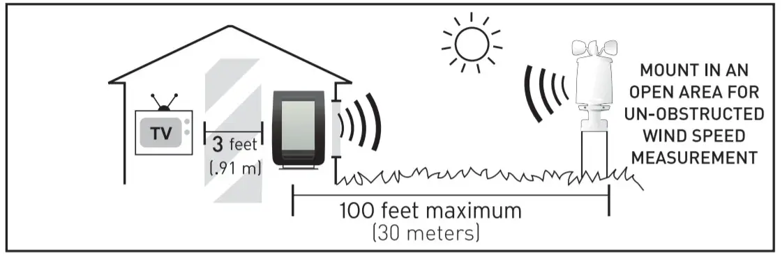
Now that setup is complete and you understand how to operate the weather station, you must choose a location to place the wireless sensor and the main unit. The wireless sensor MUST be placed less than 100 feet (30 meters] away from the main unit.This wireless weather station uses radiofrequency for communication, which is susceptible to interference from other electronic devices and large metallic items or thick walls. Always place both units at least 3 feet (.91 ml away from appliances I TV, microwave, radios, etc. 1 or objects that may interfere with the wireless communication I large metal surfaces, thick stone walls, etc. ).Please USE EXTREME CARE when handling the wireless sensor and the main unit. The wireless sensor contains sensitive electronic components and a balanced anemometer (for wind speed measurement). Care must be taken during setup and when considering placement to make certain the unit is not dropped or struck with any falling debris from trees or structures.USE caution when utilizing tools or equipment for mounting the wireless sensor. Enlist the help of another individual when necessary.Placement of Main Unit
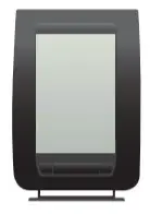 Place the main unit in a dry area free of dirt and dust.To help ensure an accurate indoor temperature measurement, be sure to place the main unit out of direct sunlight, and away from any heat sources or vents in your home. For the best atomic clock signal reception, place the main unit with the backside facing the state of Colorado.There are 2 placement options for the main unit. You may hang the main unit on a wall using the integrated hang hole. Alternatively, you may place the main unit on a tabletop or other flat surface using the included detachable tabletop display stand.
Placement of Sensor
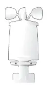 The wireless sensor MUST BE MOUNTEDOUTDOORSto observe outdoor temperature/humidity/wind speed and relay the information to the main unit display. The wireless sensor must be placed less than 100feet (30 ml from the main unit.The wireless sensor must be mounted securely. It is advised that the wireless sensor be mounted well above and away from all obstructions to report the wind speed accurately. There are three main mounting options to consider:
 |
 |
“‘POLE” OR SIMILAR MOUNTING
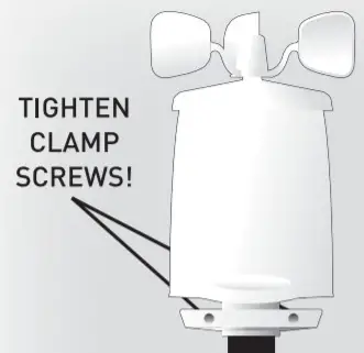 |
Mount the sensor onto a 3/4″ schedule 40 (25.8 mm O.D.l pipe (not included). PVC plastic pipe isrecommended over a metallic pipe due to the lower risk of lightning strikes. |
| INCLUDED MOUNTING BRACKET NOT USED | Insert the pole completely into the bottom of the wireless sensor. Tighten the “CLAMP” screwssecurely to make certain the wireless sensor will not fall or slide off of the pole in high winds. |
| (POLE NOT INCLUDED) | Use caution when installing a sensor or erecting the pole. Do not install during electrical storms.Do not place a pole or sensor near electrical transmission lines or electrical equipment. |
SECTION 5 · PRODUCT SPECIFICATIONS
Measurement RangesTemperatureMain Unit: 32°F to 122°F / 0°C to 50°CWireless Sensor: -40°F to 158°F / -40°C to 70°CHumidityMain Unit: 16% to 98% Relative HumidityWireless Sensor: 1% to 99% Relative HumidityWind SpeedWireless Sensor: 0 to 100 m.p.h. / 0 to 161 kph
Specifications
Power RequirementsMain Unit: 3 x “M’ alkaline or lithium batteries Wireless Sensor: 4 x “M” alkaline or lithium batteriesAtomic ClockFrequency: WWVB 60KhzSynchronizes DailyWireless Communication 433 MHz Radio Frequency-Transmission every 18 seconds
Set Wireless ID
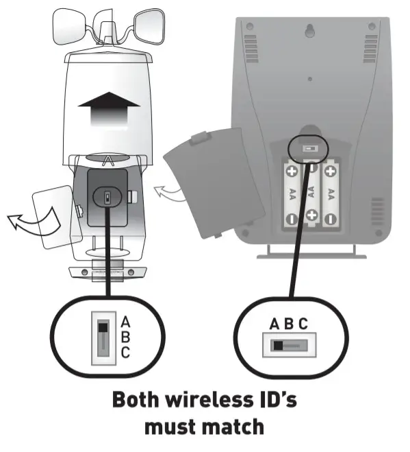 This wireless thermometer uses a long-range 433mhz radio frequency for communication.In the event that you have reception problems due to interference, both the main unit and the wireless sensor have a selectable wireless ID. The ID switches are located within the battery compartments of the main unit and the wireless sensor.You may choose A, B, or C; but both the main unit and the wirelesssensorID’smust match for successful synchronization.
Troubleshooting
|
Problem |
Possible Solution |
|
Bad Wireless Sensor Reception |
Relocate the main unit and/or the wireless sensor. Both units must be within 100 feet [30 ml from each other. Make sure both units are placed at least 3 feet [.91 ml from other electronic appliances and devices that may interfere with the wireless communication [such as TVs, microwaves, computers, etc].NOTE: It may take up to 20 minutes for the main unit to re-synchronize with the sensor when batteries are replaced.Use lithium batteries in the sensor when the temperature is below -4°F (-20°C). |
|
Bad Atomic Clock Reception |
Rotate the wireless sensor 90° on its mounting point. Make certain there are no large stone or metallic surfaces disrupting the signal line-of-sight to the state of Colorado.Make sure the main unit and wireless sensor are placed at least 3 feet [.91 ml from other electronic appliances and devices that may interfere with the wireless communication [such as TVs, microwaves, computers, etc].Large metallic surfaces will interfere with the atomic clock signal. |
|
No Wireless Sensor Data[no communication] |
If wireless reception is bad [no bars]. see .. Bad Reception .. section above. The wireless ID setting on each unit must match for all units to communicate properly. See .. Set Wireless ID” on the previous page. |
|
Main Unit Display Not Working |
Make certain that the batteries are installed correctly and that they are contacting the terminals. Make certain all contacts are clean.The batteries may need replacing. |
 no bars
 no bars and flashingantenna icon
 Please DO NOT return the product to the retail store. For technical assistance and product return information, please callCustomer Care: 877-221-1252 Mon. – Fri. 8:00 A.M. to 4:45 P.M.[CST] www.chaneyinstrument.comTo receive product information, register your product online. It’s quick and easy Log on to http://www.chaneyinstrument.com/product_reg.htm
LIMITED ONE YEAR WARRANTY
Chaney Instrument Company warrants that all products it manufactures be of good material and workmanship and to be free of defects if properly installed and operated for a period of one year from the date of purchase. REMEOYFORBREACHOFTHIS WARRANTY IS EXPRESSLY LIMITED TO REPAIR OR REPLACEMENT OF DEFECTIVE ITEMS.Any product which, under normal use and service, is proven to breach the warranty contained herein within one year from the date of sale will, upon examination by Chaney, and at its sole option, be repaired or replaced by Chaney. In all cases, transportation costs and charges for returned goods shall be paid for by the purchaser. Chaneyherebydisclaims all responsibility for such transportation costs and charges. This warranty will not be breached, and Chaney will give no credit for products it manufactures which shall have received normal wear and tear, been damaged, tampered with, abused, improperly installed, damaged in shipping, or repaired or altered by others than authorized representatives of Chaney.THE ABOVE-DESCRIBED WARRANTY IS EXPRESSLY IN LIEU OF ALL OTHER WARRANTIES, EXPRESS OR IMPLIED, AND ALL OTHER WARRANTIES ARE HEREBY EXPRESSLY DISCLAIMED, INCLUDING WITHOUT LIMITATION THE IMPLIED WARRANTY OF MERCHANTABILITY AND THE IMPLIED WARRANTY OF FITNESS FOR A PARTICULAR PURPOSE. CHANEY EXPRESSLY DISCLAIMS ALL LIABILITY FOR SPECIAL, CONSEQUENTIAL, OR INCIDENTAL DAMAGES, WHETHER ARISING IN TORT OR BY CONTRACT FROM ANY BREACH OF THIS WARRANTY. SOME STATES DO NOT ALLOW THE EXCLUSION OR LIMITATION OF INCIDENTAL OR CONSEQUENTIAL DAMAGES, SO THE ABOVE LIMITATION OR EXCLUSION MAY NOT APPLY TO YOU. CHANEY FURTHER DISCLAIMS ALL LIABILITY FROM PERSONAL INJURY RELATING TO ITS PRODUCTS TO THE EXTENT PERMITTED BY LAW. BY ACCEPTANCE OF ANY OF CHANEY’S EQUIPMENT OR PRODUCTS, THE PURCHASER ASSUMES ALL LIABILITY FOR THE CONSEQUENCES ARISING FROM THEIR USE OR MISUSE. NO PERSON, FIRM, OR CORPORATION IS AUTHORIZED TO ASSUME FOR CHANEY ANYOTHER LIABILITY IN CONNECTION WITH THE SALE OF ITS PRODUCTS. FURTHERMORE, NO PERSON, FIRM, OR CORPORATION IS AUTHORIZED TO MODIFY OR WAIVE THE TERMS OF THIS PARAGRAPH, AND THE PRECEDING PARAGRAPH, UNLESS DONE IN WRITING AND SIGNED BY A DULY AUTHORIZED AGENT OF CHANEY. THIS WARRANTY GIVES YOU SPECIFIC LEGAL RIGHTS, AND YOU MAY ALSO HAVE OTHER RIGHTS WHICH VARY FROM STATE TO STATE.
For in-warranty repair, please contact:Customer Care DepartmentChaneyInstrument Company965 Wells StreetLake Geneva, WI 53147ChaneyCustomerCare877-221-1252Mon-Fri 8:00 a.m. to 4:45 p.m. CSTwww.chaneyinstrument.com
 This device complies with part 15 of the FCC rules. Operation is subject to the following two conditions:
- This device may NOT cause harmful interference, and
- This device must accept any interference received, including interference that may cause undesired operation.
NOTE: This equipment has been tested and found to comply with the limits for a Class B digital device, pursuant to Part 15 of the FCC rules. These limits are designed to provide reasonable protection against harmful interference in a residential installation.This equipment generates, uses, and can radiate radio frequency energy and, if not installed and used in accordance with the instructions, may cause harmful interference to radio communications.However, there is no guarantee that interference will not occur in a particular installation.If this equipment does cause harmful interference to radio or television reception, which can be determined by turning the equipment off and on, the user is encouraged to try to correct the interference by one or more of the following measures:
- Reorient or relocate the receiving antenna.
- Increase the separation between the equipment and the receiver.
- Connect the equipment into an outlet on a circuit different from that to which the receiver 1sconnected.
- Consult the dealer or an experienced radio/TV technician for help.
NOTE: The manufacturer is not responsible for any radio or TV interference caused by unauthorized modifications to this equipment. Such modifications could void the user’s authority to operate the equipment.
Patent numbers:5,978,738; 6,076,044; 6,597,990INST- 00634081309
References
[xyz-ips snippet=”download-snippet”]