AcuRite 00632 Weather Center Instruction Manual

Congratulations on your new AcuRite product. To ensure the best possible product performance, please read this manual in its entiretyand retain it for future reference.
Unpacking Instructions
Remove the protective film that is applied to the LCD screen prior to using this product. Locate the tab and peel off to remove.
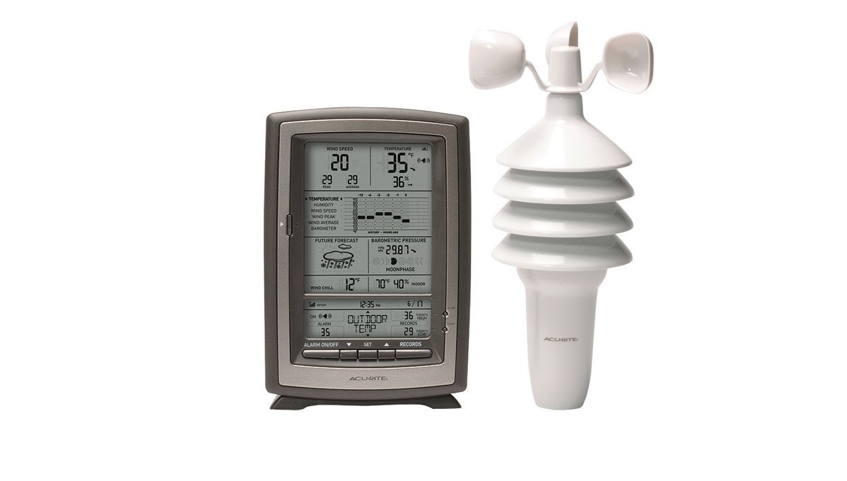
Package Contents
- Display unit with tabletop stand
- 3-in-1sensor.
- Sensor mounting bracket.
- Mounting hardware.
- Instruction Manual
FCC Information
This device complies with part 15 of FCC rules. Operation is subject to the following two conditions:
- This device may NOT cause harmful interference, and
- This device must accept any interference received, including interference that may cause undesired operation.
WARNING: Changes or modifications to this unit not expressly approved by the party responsible for compliance could void the user’s authority to operate the equipment.NOTE: This equipment has been tested and found to comply with the limits for a Class B digital device, pursuant to Part 15 of the FCC rules. These limits are designed to provide reasonable protection against harmful interference in a residential installation. This equipment generates, uses and can radiate radio frequency energy and, if not installed and used in accordance with the instructions, may cause harmful interference to radio communications. However, There is no guarantee that interference will not occur in a particular installation. If this equipment does cause harmful interference to radio or television reception, which can be determined by turning the equipment off and on, the user is encouraged to try to correct the interference by one or more of the following measures:
-
- Reorient or relocate the receiving antenna
- Increase the separation between the equipment and the receiver.
- Connect the equipment into an outlet on a circuit different from that to which the receiver is connected.
- Consult the dealer or an experienced radio/TV technician for help.
NOTE: The manufacturer is not responsible for any radio or TV interference caused by unauthorized modifications to this equipment. Such modifications could void the user authority to operate the equipment. This device complies with Industry Canada licence-exempt RSS standard(s). Operation is subject to the following two conditions:
- This device may not cause interference, and
- This device must accept any interference received, including interference that may cause undesired operation of the device.
Features & Benefits

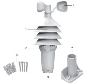
3-in-1 SENSOR
- Temperature & Humidity Sensors(internal)
- Release Lever for Battery Access
- Mounting Point
- Wind Speed Anemometer
- Mounting HardwareIncludes anchors and screws.
- Mounting Bracket
- A-B-C SwitchID code that must match display’s A-B-C switch to ensure units synchronize.
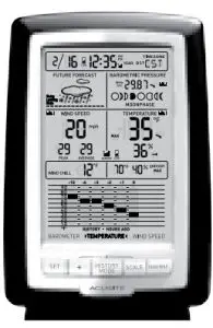
Display Unit

DISPLAY UNIT
- Date
- Low Battery Indicator
- Atomic ClockMaintains time with split-second accuracy and automatically updates for daylight saving time.
- . Atomic Clock Signal Strength
- Selected Time Zone
- Barometric Pressure Arrow icon indicates the direction the pressure is trending.
- History Chart IconIndicates data is currently displayed on the History Chart (22)
- Moon Phase
- History Chart IconIndicates data is currently displayed on the History Chart (22).
- Current Outdoor TemperatureArrow icon indicates direction temperature is trending.
- Sensor Signal Strength
- Low Sensor Battery Indicator
- Current Indoor Humidity
- High/Low Records IndicatorIndicates whether minimum or maximum records are being shown.
- Current Indoor Temperature
- Removable Tabletop Stand
- 17. MIN/MAX ButtonPress to view high or low records for temperature and humidity.
- SCALE ButtonChanges data units to either U.S. units or imperial units.
- HISTORY MODEButton Press to toggle between pressure, temperature and wind speed data on the History Chart (22).
- + ButtonFor setup preferences.
- SET ButtonFor setup preferences.
- Multi-Variable History ChartDisplays the past 12 hours of data for pressure, temperature or wind speed.
- SeasonalDisplays heat index, dew point or wind chill, depending on the current outdoor temperature.
- Average Wind SpeedBased on all wind speed readings from the past 2 minutes.
- Peak Wind SpeedHighest speed from past 60 minutes.
- Current Wind Speed
- History Chart IconIndicates data is currently displayed on the History Chart (22).
- Learning Mode IconDisappears after weather forecast self-calibration is complete.
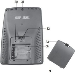
- 12 to 24 Hour Weather ForecastSelf-Calibrating Forecasting pulls data from the outdoor sensor to generate your personal forecast.BACK OF DISPLAY UNIT
- Reset ButtonFull reset to factory defaults.
- Integrated Hang HoleFor easy wall mounting
- A-B-C SwitchID code that must match sensor’s A-B-C switch to ensure units synchronize.
- Battery Compartment Cover
- Battery Compartment
SETUP
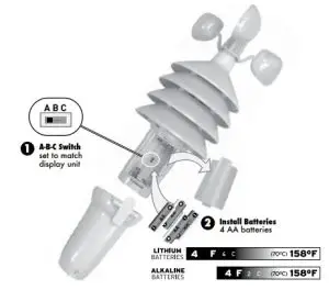
Set the A-B-C SwitchThe A-B-C switch is located inside the battery compartment. It can be set to A, B or C. However, you must select the same letter choices for both the sensor and the display unit in order for the units to synchronize.
Install or Replace BatteriesAcuRite recommends high quality alkaline or lithium batteries for the best product performance. Heavy duty or rechargeable batteries are not recommended.
The 3-in-1 sensor requires lithium batteries in low temperature function improperly. Use lithium batteries in the 3-in-1 sensor for temperatures below -4ºF / -20ºC.
- Press the release lever and pull off the lower housing of the sensor.
- Remove the battery compartment cover.
- Insert 4 x AA batteries into the battery compartment, as shown. Follow the polarity (+/-) diagram in the battery compartment.
- Replace the battery cover and lower housing of the sensor.
Display Unit Setup
AcuRite recommends high quality alkaline batteries for the best product performance. Heavy duty or rechargeable batteries are not recommended.
- Set the A-B-C SwitchLocate the A-B-C switch inside 1. Remove the battery the battery compartment. Set compartment cover. the A-B-C switch to A, B or C. You must select the same letter choices for both the display unit and the sensor in order for the units to synchronize.
- Install or Replace Batteries
- Remove the battery the battery compartment cover.
- . Insert 3 x AA alkaline batteries into the battery compartment, as shown. Follow the polarity (+/-) diagram in the battery 2 compartment
- Replace the battery cove

 PLEASE DISPOSE OF OLD OR DEFECTIVE BATTERIES IN AN ENVIRONMENTALLY SAFE WAY AND IN ACCORDANCE WITH YOUR LOCAL LAWS AND REGULATIONS .
BATTERY SAFETY: Clean the battery contacts and also those of the device prior to battery installation. Remove batteries from equipment which is not to be used for an extended period of time. Follow the polarity (+/-) diagram in the battery compartment. Promptly remove dead batteries from the device. Dispose of used batteries properly. Only batteries of the same or equivalent type as recommended are to be used. DO NOT incinerate used batteries. DO NOT dispose of batteries in free, as batteries may explode or leak. DO NOT mix old and new batteries or types of batteries (alkaline/standard). DO NOT use rechargeable batteries. DO NOT recharge non-rechargeable batteries. DO NOT short-circuit the supply terminals.
Atomic Clock
AcuRite atomic clocks use a radio-controlled signal to synchronize to the correct time broadcast by the National Institute of Standards and Technology (NIST) Radio Station WWVB, located near Fort Collins, Colorado. WWVB broadcasts the current time and date with split-second accuracy.The atomic clock and calendar will maintain the correct time and date, and automatically update for daylight saving time to provide the most accurate timekeeping standard possible.Please note: Signal reception is normally better at night and when the weather is clear. The atomic signal generally takes a few hours to synchronize, so it is important to manually set the time and date after powering on the display.
Set the Time & DatePress and hold the “SET” button, located on the front of the display unit, for 3 seconds to enter SET MODE. Once in set mode, the preference you are currently setting will blink on the display.To adjust the currently selected (flashing) item, press and release the “+” button (press and HOLD to fast adjust).To save your adjustments, press and release the “SET” button again to adjust the next preference. The preference set order is as follows: TIME ZONE ( EST AST HAT AKT PST MST CST ) DST (Daylight Saving Time ON or OFF)*CLOCK HOURCLOCK MINUTECALENDAR YEARCALENDAR MONTHCALENDAR DATE*If you live in an area that observes DST, DST should be set to ON, even if it is not currently Daylight Saving Time.You will automatically exit SET MODE if no buttons are pressed for 30 seconds. Enter setup mode at any time by pressing and holding the “SET” button.
Select Measurement Units
To select between U.S. standard units or imperial units, press the “SCALE” button.
| Measurement | U.S. Standard Units | Imperial Units |
| Temperature | Degrees Fahrenheit (ºF) | Degrees Celsius (ºC) |
| Barometric Pressure | inHg (inches of mercury) | hPa (Hectopascal) |
| Wind Speed | Miles per hour (mph) | Kilometers per hour (kph) |
Placement for Maximum Accuracy
AcuRite sensors are sensitive to surrounding environmental conditions. Proper placement of both the display unit and the sensor are critical to the accuracy and performance of this product.
 Display Unit PlacementPlace the display unit in a dry area free of dirt and dust. To ensure accurate temperature measurement, place out of direct sunlight and away from heat sources or vents. Display unit stands upright for tabletop use or is wall-mountable.
![]() 3-in-1 Sensor PlacementThe 3-in-1 sensor is designed to remain outdoors all year long. Choose an open location with no obstructions above or around the sensor for the most accurate measurements.
3-in-1 Sensor PlacementThe 3-in-1 sensor is designed to remain outdoors all year long. Choose an open location with no obstructions above or around the sensor for the most accurate measurements.
Important Placement GuidelinesDisplay unit and sensor must be within 330 feet (100 m) of each other.MAXIMIZE WIRELESS RANGEPlace units away from large metallic items, thick walls, metal surfaces, or other objects that may limit wireless communication.PREVENT WIRELESS INTERFERENCEPlace both units at least 3 feet (.9 m) away from electronic devices (TV, computer, microwave, radio, etc.).LOCATE AWAY FROM HEAT SOURCESPosition sensor away from heaters, air conditioners, chimneys, exhaust vents, asphalt and concrete (surfaces that radiate heat). LOCATE AWAY FROM HUMIDITY SOURCESAvoid installing the sensor near pools, spas, or other bodies of water. Water sources may impact humidity accuracy.LOCATE AWAY FROM SPRINKLER HEADSDO NOT install the sensor where it will be sprayed by a sprinkler system. This may force water inside the sensor.LOCATE AWAY FROM WIND OBSTRUCTIONSDO NOT mount the sensor with obstructions around it. Consider a location that is a wide open area, with few structures around to ensure accurate wind measurement.
3-in-1 Sensor Installation Guidelines
INSTALLATION HEIGHT Mount the sensor at least 5 feet (1.5 meters) off the ground (higher is better for wind measurement) in an open area. Secure to fence post, 4”x4” wood, 3/4” pole, etc. (not included)LEVEL INSTALLATION Use a bubble level (not included) to ensure level installation for accurate wind measurement.
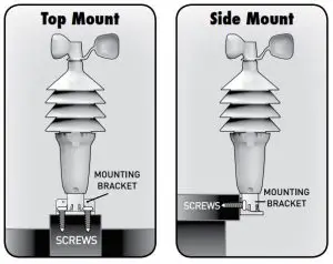
Top or Side Mount
- Insert the mounting base into the hole on the bottom of the sensor.
- Use one of the screws included in the hardware bag to fasten the lower sensor housing to the mounting base.
- . Make sure the sensor is level using a bubble level.
- Fasten mounting base to a post or railing using 2 screws.
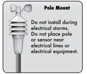
Pole Mount
- Insert pole (we recommend 3/4” schedule 40 PVC / 25.8 mm O.D., not included) or similar item all the way into the hole on the bottom of the sensor. Note: Mounting base is not used.
- Use one of the screws included in the hardware bag to fasten the lower sensor housing securely to the pole.
- Make sure the sensor is level using a bubble level.The 3-in-1 sensor is now ready to use.
Basic Setup is Complete
The 3-in-1 sensor will now synchronize with the display unit. It may take a few minutes for synchronization to complete. If both or one of the units appear to be functioning improperly, please refer to the troubleshooting section.
Using The Weather Center
Learning Mode
Self-Calibrating Forecasting use a unique algorithm to analyze changes in pressure over a time period (called Learning Mode) to determine your altitude. After 14 days, the Learning Mode icon disappears from the display screen. At this point, the self-calibrated pressure is tuned in to your location and the unit is ready for superior weather prediction.
Weather Forecast AcuRite’s patented Self-Calibrating Forecasting provides your personal forecast of weather conditions for the next 12 to 24 hours by collecting data from the sensor in your backyard. It generates a forecast with pinpoint accuracy – personalized for your exact location View the complete list of icons at www.AcuRite.com/acurite-icons
Multi-Variable History ChartThe multi-variable history chart lets you monitor the change in conditions over the last 12 hour time period (-12, -6, -3, -2, -1, 0). Toggle between barometric pressure, temperature and wind speed readings.Wind SpeedThe Wind Speed area of the display features WIND SPEED PEAK, AVERAGE and CURRENT WIND SPEED. The multi-variable history chart lets you monitor the change in AVERAGE hourly wind speed.Barometric PressureSubtle variations in barometric pressure greatly impact the weather. This weather center displays the current pressure with an arrow icon to indicate the direction the pressure is trending (FALLING, STEADY, or RISING). The multivariable history chart lets you monitor the change in pressure over time.
High & Low RecordsThe “MIN/MAX” button displays minimum and maximum recordings for outdoor and indoor temperature and humidity. To view the MINIMUM temperature and humidity readings, press and release the “MIN/MAX” button until the “MIN” icon appears on the display next to the low records. To view the MAXIMUM temperature and humidity readings, press and release the “MIN/MAX” button until the “MAX” icon appears on the display next to the high records.To reset the MINIMUM records, first view the MIN records by pressing the “MIN/MAX” button until the “MIN” icon appears on the display. While viewing the MIN records, press and hold the “+” and “SCALE” buttons simultaneously for 3 seconds. Dashes will display to confirm all MIN values have been cleared.To reset the MAXIMUM records, first view the MAX records by pressing the “MIN/MAX” button until the “MAX” icon appears on the display. While viewing the MAX records, press and hold the “+” and “SCALE” buttons simultaneously for 3 seconds. Dashes will display to confirm all MAX values have been cleared.
Troubleshooting
|
Problem |
Possible Solution |
|
No outdoor sensor reception no bars |
|

| Problem | Possible Solution |
| Outdoor temperature is flashing or showing dashes | Flashing of the outdoor temperature may be an indication of wireless interference. • Make sure the A-B-C switch in the battery compartments of both the display unit and sensor are switched to the same letter. You may choose A, B or C; but both units must match to sync up. |
| Inaccurate wind readings | • What is wind reading being compared to? Pro weather stations are typically mounted at 30 ft high or more. Make sure to compare data using a sensor positioned at the same mounting height. • Check location of the sensor. Ensure it’s mounted a minimum of 5 ft in the air with no obstructions around it (within several feet) •Ensure wind cups are spinning freely. If they hesitate or stop try lubricating with graphite powder or spray lubricant. |
| Display screen not working | • Check that the batteries are installed correctly. Batteries may need to be replaced. • Reset the display by pressing the reset button, located on the back of the display unit. Date and time will need to be entered after a reset. |
| Inaccurate forecast | • Weather Forecast icon predicts conditions for the next 12 to 24 hours, not current conditions. • Has Learning Mode icon disappeared from the display unit? Learning Mode must complete before forecast and pressure will be accurate.
• Allow unit to run continuously for 33 days. Battery removal or resetting the display unit will restart Learning Mode. After 14 days, forecast should be fairly accurate, however Learning Mode calibrates for a total of 33 days. |
| Inaccurate temperature or humidity | • Make sure both the display unit and 3-in-1 sensor are placed out of direct sunlight and away from any heat sources or vents (see page 9). • Make sure both units are positioned away from moisture sources (see page 9). • Make sure 3-in-1 sensor is mounted at least 5 ft off of the ground. |
Care & Maintenance
Display Unit CareClean with a soft, damp cloth. Do not use caustic cleaners or abrasives. Keep away from dust, dirt and moisture. Clean ventilation ports regularly with a gentle puff of air.
3-in-1 Sensor CareClean the SensorClean with a soft, damp cloth. Do not use caustic cleaners or abrasives Insect PreventionInsects may cause obstructions and interrupt data by nesting in or on the 3 in-1 sensor. To limit this problem, spray the OUTSIDE of the sensor with a household insect repellent. Consult the insect repellent instructions prior to use.Snow & Freezing WeatherThe 3-in-1 sensor will not be damaged by freezing conditions.Clean the Wind AnemometerRemove foreign matter from the outside of the sensor for free movement of the wind anemometer. If needed, use a small amount of spray lubricant, clear silicone or graphite powder on the anemometer for improved movement.
| TEMPERATURE RANGE | Outdoor: -40ºF to 158ºF; -40ºC to 70ºC |
| Indoor: 32ºF to 122ºF; 0ºC to 50ºC | |
| HUMIDITY RANGE | Outdoor: 1% to 99% |
| Indoor: 16% to 98% | |
| WIND SPEED | 0 to 99 mph; 0 to 159 kph |
| WIRELESS RANGE | 330ft / 100m depending on home construction materials |
| OPERATING FREQUENCY | 433 MHz |
| POWER | Display: 3 x AA alkaline batteries Sensor: 4 x AA alkaline or lithium batteries |
| DATA REPORTING | Wind Speed: 18 second updates Outdoor temperature & humidity: 18 second updates Indoor temperature & humidity: 60 second updates |
Customer Support
AcuRite customer support is committed to providing you with best-inclass service. For assistance, please have the model number of this product available and contact us in any of the following ways:
 (877) 221-1252
 ![]() [email protected]
[email protected]
24/7 support at www.AcuRite.com
► Installation Videos ► Register your Product► Instruction Manuals ► Support User Forum► Replacement Parts ► Submit Feedback & Ideas

It’s more than accurate, it’s ![]()
AcuRite offers an extensive assortment of precision instruments, designed to provide you with information you can depend on to Plan your day with confidence™.
References
[xyz-ips snippet=”download-snippet”]