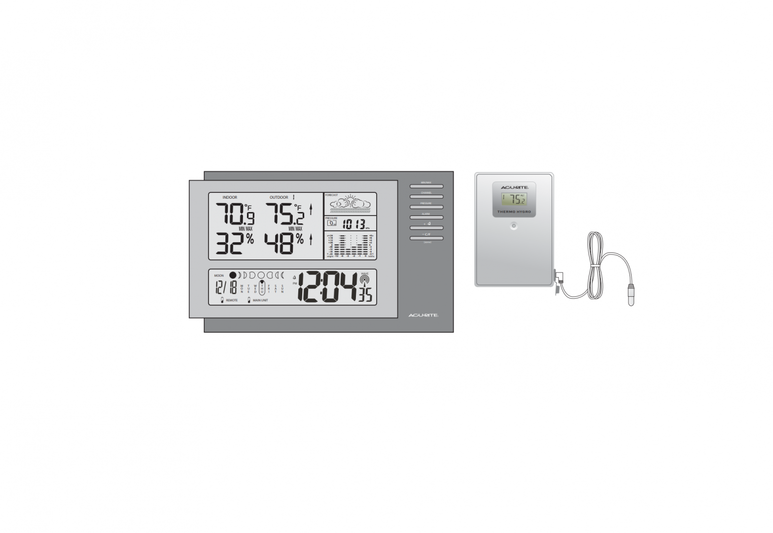
AcuRite 00973 Deluxe Wireless Weather Station & Atomic Clock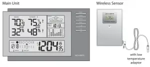
Thank You! We appreciate you for purchasing the new generation radio controlled wireless weather station and atomic clock. This instrument is designed and engineered with state-of-the-art technology and components. It will provide these accurate and reliable measurements: date, time, barometric pressure, and indoor/outdoor temperatures and humidity levels. A weather forecast component rounds out the features of this versatile weather clock.
CHECK PACKAGE CONTENTS
* dimensions approximate
- (1) Main Unit – 9.25” x 6” x 1”*
- (1) Thermo. Hygro. remote sensor – 2.5” x 3.75” x 1”*
- (1) 10’* wired low temperature adaptor
- (2) 1” (2.5cm) screws with plastic anchors
- (1) Instruction manual
READ
Please read this entire manual carefully before you set up the instrument and begin to use it. In this way you can become familiar with the features of the weather station & clock to get the most benefit from it.
INSTALL BATTERIES
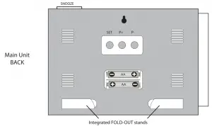
Main Unit: Always install batteries into the main unit first. On the back of the unit, remove the battery compartment cover. Insert 2 AA alkaline (or lithium – See NOTES below) batteries. Replace the cover.
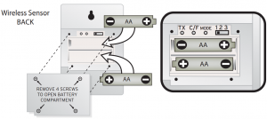
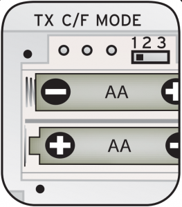
Wireless Sensor: After batteries have been put into the main unit, remove the 4 screws to remove the back cover of the wireless sensor. Insert 2 AA alkaline (or lithium) batteries.Press the “TX” button and replace the back cover and the 4 screws on the sensor. Put the sensor aside for now, and continue to learn about the main unit. Later, in part 5 of this manual you’ll learn more about the wireless sensor.
NOTE: When replacing the batteries for the wireless sensor, remove the batteries from the sensor and clear the sensor’s channel on the main unit by pressing and holding the CHANNEL button when the corresponding channel is displayed. Reinstall the batteries into the wireless sensor and press and release the TX button to synchronize the units.
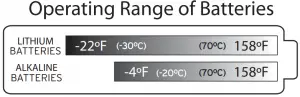 Severe cold (below -4º F/-20º C) can cause alkaline batteries to freeze and function improperly. Use lithium batteries in extremely low temperature conditions to ensure continued operation. Severe cold (below -4º F/-20º C) can cause alkaline batteries to freeze and function improperly. Use lithium batteries in extremely low temperature conditions to ensure continued operation. |
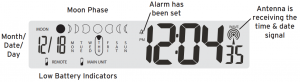
![]() Low Battery Indicator:When the battery level is low for the main unit or the wireless sensor, the low battery level icons will illuminate
Low Battery Indicator:When the battery level is low for the main unit or the wireless sensor, the low battery level icons will illuminate
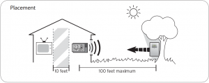
CHOOSE WHERE TO PLACE THE MAIN UNIT and WIRELESS SENSOR
Main Unit: Choose wall mount or table-top placement.
- Choose a location for each unit that is at least 10 feet away from other electronic devices that may interfere with the wireless signal.
- Wall mounting: Use the mounting slot on the back of the unit to hang it from one of the supplied screws.
- Table-top placement: Fold out the integrated table-top stands to place the main unit on a table-top surface.
Wireless Sensor: When placing the sensor, consider these things:
- Although the sensor is designed for outdoor use, placement in a protected area will prolong its life.
- Mounting: Use the mounting slot on the back of the unit to hang it from one of the supplied screws.
- The sensor must be within 100 feet (30 meters) of the main unit.
- The sensor is resistant to weather and to water. It is NOT WATERPROOF.
- Prolonged exposure to cold weather may cause damage to the LCD panel.
- Wireless sensor can be placed outdoors to observe outdoor temperatures and humidity.
- In extremely cold temperatures, it may be necessary to use the included low temperature adaptor to ensure continued operation. This involves bringing the wireless sensor indoors and routing the wired temperature adaptor outside to observe outdoor temperatures. See page 4 for more information.

Using the included LOW TEMPERATURE ADAPTOR
The wireless sensor will operate normally down to -4 ºF. Below -4 ºF, the electronics may operate erratically or become non-functional until the temperature raises again.In case temperatures fall below -4ºF, bring the wireless sensor indoors and use the included low temperature adaptor by running the wire out through a soft seal opening such as a window or door. When routing the wire for the low temperature adaptor, make certain that the wire will not be severed or damaged.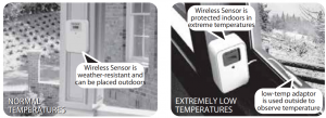

NOTE: The wired TEMPERATURE ADAPTOR only observes temperature, not humidity.If the adaptor is placed outdoors, and the wireless sensor is indoors- the wireless sensor will only transmit the indoor humidity reading & the outdoor temp. reading.
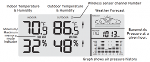
PREVIEW THE DISPLAY
Main Unit – Upper Display – Weather
Main Unit – Lower Display – Date and Clock
Wireless Sensor – Display
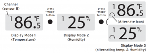
Press the “MODE” button inside the back of the wireless sensor to display temperature and/or humidity in one of three ways:1) Temperature continuously,2) Humidity continuously, or3) Temperature for 5 seconds, then humidity for 5 secondsNOTE: The sensor’s display setting does not affect the main unit’s display.
MAIN UNITOperation buttons are located on the front and back of the main unit |
||
|
BUTTON NAME |
PRESS & RELEASE |
PRESS & HOLD FOR 3 SECONDS |
|
CHANNEL |
choose channel 1,2, or 3 | clears the current channel |
| MIN/MAX (memory) | read maximum & minimum values for temperatures, humidity (both indoor & outdoor) |
N/A |
|
PRESSURE |
view pressure history & confirm settings | adjust current pressure |
| ALARM | view alarm time for 5 seconds |
set alarm time |
|
SET |
starts radio-controlled time synchronization | to set clock & calendar manually |
| + |
turn alarm on/off OR raise a setting by one unit |
fast advance setting mode |
|
– C/F |
select ºC or ºF OR lower a setting by one unit | fast reverse in time setting mode & current time zone setting |
| P+ | to make adjustments to air pressure |
N/A |
|
P- |
to make adjustments to air pressure | to select hPa or inHg pressure units |
| SNOOZE | silence the alarm for 5 minutes |
N/A |
WIRELESS SENSOR |
||
|
BUTTON NAME |
PRESS & RELEASE |
 |
|
TX |
sends wireless signal to main unit |
|
|
C/F |
select ºC or ºF display mode for wireless sensor |
|
|
Mode |
choose display mode for wireless sensor |
|
|
CH (1,2or 3) |
choose channel 1, 2, or 3 |
MAIN UNIT FEATURES
Radio-controlled Clock : The unit starts synchronizing the clock after the 1st channel of the wireless sensor begins to send its information to the main unit. (This is called registration.) The built-in antenna receives the official time signal from the US Government’s National Institute of Standards and Technology. A microchip translates the time signal and adjusts the time display for the correct time, and date.
Manually Setting the Time and Date:1) Press and hold the “SET” button, and the year display will flash on the screen. Using the “+” and “– ” buttons set the year. When the correct year is entered, press and release the “SET” button to confirm the setting.2) Once you have confirmed the year, follow the same procedure to set the month, date, hour, minute, 12 or 24-hour time preference, and DST (Daylight Saving Time).
NOTE: You cannot change any settings manually if the clock is attempting to synchronize. Allow the clock to finish the cycle, and then manual changes can be made if the clock has not automatically acquired the signal and set itself to the correct time.
Time Zone:Note: Default setting is Pacific Time. If you live outside of the Pacific Time Zone, you will need to set your Time Zone using the following procedure:1) Press and hold the “– / C/F” button on the front of the clock for three seconds. The area of the clock where the seconds are usually displayed will be replaced with the letter for the time zone it is currently set in.2) If set to the default setting, you will see a flashing letter “P” on the screen after pressing and holding the “– / C/F” button. Press and release the “– / C/F” button until the letter shown corresponds to your time zone:
P = Paciÿc M = Mountain C = Central E = Eastern
Once your zone is displayed, there is nothing more you need to do. After about 3 seconds, the seconds will once again be displayed on your clock.
The antenna icon (![]() ) will flash on and off during synchronization. If the icon disappears, this indicates that the radio signal is not available. If you are unable to obtain a signal after a long period of time, try placing the base unit away from sources of interference such as computers, televisions, cordless phone bases, and other electronic items.
) will flash on and off during synchronization. If the icon disappears, this indicates that the radio signal is not available. If you are unable to obtain a signal after a long period of time, try placing the base unit away from sources of interference such as computers, televisions, cordless phone bases, and other electronic items.
Note: The synchronization process can take 24-72 hours.
Celsius/Fahrenheit:Press and release the “–” (minus) button. A beep sounds, and the display will change to either Fahrenheit or Celsius.
Barometer Set Up:When the main unit power comes on, the pressure section will display 1013 for 60 seconds. The digital barometer will calculate and forecast the weather conditions. Your instrument will not provide a reliable forecast unless your current barometric pressure is set. See page 8 for barometric pressure adjustment information.
Adjust the barometric pressure to reflect your current conditions:NOTE: Please see http://weather.unisys.com/surface/sfc_con_pres.html to help set and adjust the barometric pressure.1) Hold “PRESSURE” button for 3 seconds2) Press “P+” , and/or “P-” to adjust the air pressure according to the current pressure.3) Press the “PRESSURE” button to confirm the setting
Moon Phase: ![]() The moon phase will automatically display based on the calendrer date. The moon phase display will scroll from left to right, and pause for about 5 seconds to display the current moon phase. NOTE: the moon phase will not be correct unless the date and year are programmed correctly.
The moon phase will automatically display based on the calendrer date. The moon phase display will scroll from left to right, and pause for about 5 seconds to display the current moon phase. NOTE: the moon phase will not be correct unless the date and year are programmed correctly.
OTHER ADJUSTMENTS
Changing the Pressure Units: To change the scale between mb (milibars) hPA (hecto Pascals) and inHg (inches of mercury), hold “P-” for three seconds.
View Pressure History: To view air pressure from 0 (current) to the past 12 hours, press the “PRESSURE” button. The hour is displayed in the small box in the pressure portion of the upper display. Each time you press “PRESSURE”, the value changes to that of the previous hour.
NOTE: The sample base station Upper Display (illustrated in section 5) shows what the pressure is, the current hour being zero (0). This pressure history is available only after the barometer has operated and kept pressure data for 12 continuous hours.
Barometer History Graph: The bar chart just below the air pressure display, shows the pressure readings (range from +0.24 inHg to –0.24 inHg/ –8 hPa mb to +8 hPa mb) of the current and past 1, 2, 3, 6 and 12 hour periods.
WEATHER FORECASTINGThe main unit predicts weather conditions of the next 12 – 24 hours based on the changes in atmospheric pressure. The coverage area is approximately 19-31 miles (30 – 50 km). The weather forecast is based on atmospheric pressure changes and is approximately 70-75% correct. As weather conditions cannot be 100% correctly forecasted, we cannot be responsible for any loss caused by an incorrect forecast.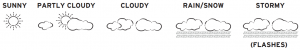
Trend Indicators:Arrow icons in the upper display will indicate the following trends: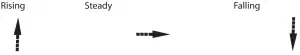
The arrow icons will indicate rising, steady or falling if the temperature or humidity change is more than 1 unit (degree/percent) within an hour.
SETTING THE ALARM:
1) Hold “ALARM” for 3 seconds.2) The hour number(s) flash. Press “+” or “-” to enter the desired hour. Press “ALARM” to confirm the hour setting.3) The minute number(s) flash. Press “+” or “-” to enter the desired minute.Press “ALARM” to confirm the minute setting.
To view the alarm time, press the “ALARM” button during the normal operating mode.Alarm time will display for five seconds. Then, the current time is displayed.
To Turn the Alarm On and O°: Press the “+” button during the normal operating mode.
To Turn o° the Alarm for One Day: To turn the alarm off for one day, press the “ALARM” button when the alarm sounds
Snooze:When the alarm sounds, press the “SNOOZE” button to trigger the snooze feature. The alarm is silenced for five minutes. Then, it will sound an alarm again.
MIN/ MAX MEMORY:Press the “MEMORY” button to view the maximum values (Inside/Outside Temperature and Humidity) for 5 seconds. Press the “MEMORY” button again to view the minimum memory.
The memory will automatically refresh every 24 hours.
NOTE: The air pressure record will not be cleared manually, but instead will be cleared automatically every 12 hours.
MULTIPLE WIRELESS SENSORS
The main unit supports up to three wireless sensors. Each additional wireless sensor must be designated a different channel number. Assigning different channel numbers differentiate each sensors temperature and hygrometer readings for the main units’ display.
Additional wireless sensors are sold separately. Call 1-800-556-2548 to order.WIRELESS SENSOR MODEL # 01022
1) Open each sensor by removing the 4 screws and the cover.2) Install batteries, see section 3.3) Use the interior slide switch to select a channel – 1, 2, or 3.4) Choose Celsius or Fahrenheit with the C/F button, for the sensor display.5) With the “MODE” button choose what you want the sensor display to show:Temperature only, Humidity only, or Temperature and humidity, alternating.6) Press the “TX” button to send a signal to the base station.7) Replace the cover and the 4 screws.8) Mount the sensor. See section 4 for placement of the wireless sensor unit.
PRODUCT SPECIFICATIONS
| Indoor main unit | 0º C to + 50º C (+32º F to +122º F) |
| Outdoor/Indoor humidity | 20% – 99% RH |
| Wireless sensor with low-temp adaptor | -20º C to +70º C (-4º F to +158º F)30º C to +70º C (-22ºF to +158º F) |
| Barometer | 900 to 1050 mb/hPa |
| Channel | maximum of three wireless sensors |
| Transmission | up to 30M (100 ft.) open area, RF434 MHz |
| Resolution | 0.1º for temperature, 1% for humidity, 1 hPa mb for pressure |
| Clock | WWVB radio-controlled, quartz back-up |
| Batteries | AA x 2 alkaline for main unit; AA x 2 alkaline for wireless sensor |
|
Do not return product to retail store. For Technical Assistance and product return information, please call Customer Care:877-221-1252HOURS: Monday through Friday from 8:00 a.m. to 4:45 pm CST |
NOTE: THE MANUFACTURER IS NOT RESPONSIBLE FOR ANY RADIO OR TV INTERFERENCE CAUSED BY UNAUTHORIZED MODIFICATIONS TO THIS EQUIPMENT. SUCHMODIFICATIONS COULD VOID THE USER AUTHORITY TO OPERATE THE EQUIPM
 NOTE: This equipment has been tested and found to comply with the limits for a Class B digital device, pursuant to Part 15 of the FCC Rules. These limits are designed to provide reasonable protection against harmful interference i a residential installation. This equipment generates, uses and can radiate radio frequency energy and, if not installed and used in accordance with the instructions, may cause harmful interference to radio communications. However, there is no guarantee that interference will not occur in a particular installation.If this equipment does cause harmful interference to radio or television reception, which can be determined by turning the equipment off and on, the user is encouraged to try to correct the interference by one or more of the following measures:— Reorient or relocate the receiving antenna.— Increase the separation between the equipment and receiver.— Connect the equipment into an outlet on a circuit different from that to which the receiver is connected.— Consult the dealer or an experienced radio/TV technician for help.
 |
PLEASE DISPOSE OF OLD OR DEFECTIVE BATTERIES IN AN ENVIRONMENTALLY SAFE WAY IN ACCORDANCE WITH YOUR LOCAL REGULATION |
 |
If at any time in the future you need to dispose of this product please note that:Waste electrical products should not be disposed together with household waste.Please recycle where facilities exist. Check with your local Authority or retailer for recycling advice |
LIMITED WARRANTY – INTERNATIONAL
Consumer may have more remedies at law than follows. Chaney Instrument Company warrants to the owner, this product to be free from defect in material and workmanship for one year from date of purchase. CHANEY INSTRUMENT SHALL NOT BE LIABLE FOR ANY INCIDENTAL, INDIRECT OR CONSEQUENTIAL DAMAGES, WHETHER ARISING IN CONTRACT OR TORT. Chaney Instrument’s obligation (at its option) is limited to repair or replace this product. For in-warranty repair, send product, accompanied by Guarantee, bearing Dealer’s name and date of purchase, with $5.00 to cover handling and postage, to:
Chaney Instrument Company965 Wells StreetLake Geneva, Wisconsin 53147
www.chaneyinstrument.comTel: 877-221-1252Made in China
![]()
References
[xyz-ips snippet=”download-snippet”]