
ADJ 12PX Hex/12PX Hex Pearl Instruction Manual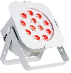
©2021 ADJ Products, LLC all rights reserved. Information, specifications, diagrams, images, and instructions herein are subject to change without notice. ADJ Products, LLC logo and identifying product names and numbers herein are trademarks of ADJ Products, LLC. Copyright protection claimed includes all forms and matters of copyrightable materials and information now allowed by statutory or judicial law or hereinafter granted. Product names used in this document may be trademarks or registered trademarks of their respective companies and are hereby acknowledged. All non-ADJ Products, LLC brands and product names are trademarks or registered trademarks of their respective companies.
ADJ Products, LLC and all affiliated companies hereby disclaim any and all liabilities for property, equipment, building, and electrical damages, injuries to any persons, and direct or indirect economic loss associated with the use or reliance of any information contained within this document, and/or as a result of the improper, unsafe, unsufficient and negligent assembly, installation, rigging, and operation of this product.
DOCUMENT VERSION
Please check www.adj.com for the latest revision/update of this guide.
Introduction
Unpacking: Thank you for purchasing the 12PX Hex/12PX Hex Pearl by ADJ Products, LLC. Every 12PX Hex/12PX Hex Pearl has been thoroughly tested and has been shipped in perfect operating condition. Carefully check the shipping carton for damage that may have occurred during shipping. If the carton appears to be damaged, carefully inspect your fixture for any damage and be sure all accessories necessary to operate the unit has arrived intact. In the case damage has been found or parts are missing, please contact our toll free customer support number for further instructions. Do not return this unit to your dealer without first contacting customer support.
Introduction: The 12PX Hex/12PX Hex Pearl is a DMX intelligent, LED par fixture. This fixture can be used in a stand alone mode or connected in a Primary/Secondary configuration. This par has five operating modes: Sound Active mode, Program mode, RGBWA + UV dimmer mode, Static Color mode, and DMX control mode. The 12PX Hex/12PX Hex Pearl have 4 DMX channel modes; 6, 7, 8, & 12.
Customer Support: ADJ Products, LLC provides a customer support line, to provide set up help and to answer any question should you encounter problems during your set up or initial operation. You may also visit us on the web at www.adj.com for any comments or suggestions. Service Hours are Monday through Friday 8:00 a.m. to 4:30 p.m. Pacific Standard Time.
Voice: (323) 582-2650Fax: (323) 582-2941E-mail: [email protected]
Warning! To prevent or reduce the risk of electrical shock or fire, do not expose this unit to rain or moisture.
Caution! There are no user serviceable parts inside this unit. Do not attempt any repairs yourself, doing so will void your manufactures warranty. In the unlikely event your unit may require service please contact ADJ Products, LLC.
PLEASE recycle the shipping carton when ever possible.
Features
- Multi-Colors
- Five Operating Modes
- Electronic Dimming 0-100%
- 5 Dimmer Curves
- DMX-512 protocol
- 3-Pin & 5-Pin DMX Connection
- Four DMX Modes: 6 Channel Mode, 7 Channel Mode, 8 Channel Mode, and 12 Channel Mode.
- Dotz Par RF Compatiable (Not Included)
- Multiple Unit Power Linking (See page 21)
Included:
- 1 x Power Cable
- 1 x Gel Frame Holder & Gel Frame
Warranty Registration
The 12PX Hex and 12PX Hex Pearl carry a 2 year limited warranty. Please fill out the enclosed warranty card to validate your purchase. All returned service items whether under warranty or not, must be freight pre-paid and accompany a return authorization (R.A.) number. The R.A. number must be clearly written on the outside of the return package. A brief description of the problem as well as the R.A. number must also be written down on a piece of paper included in the shipping carton. If the unit is under warranty, you must provide a copy of your proof of purchase invoice. You may obtain a R.A. number by contacting our customer support team on our customer support number. All packages returned to the service department not displaying a R.A. number on the outside of the package will be returned to the shipper.
Installation
The unit should be mounted using a mounting clamp (not provided), affixing it to the mounting bracket that is provided with the unit. Always ensure that the unit is firmly fixed to avoid vibration and slipping while operating. Always ensure that the structure to which you are attaching the unit is secure and is able to support a weight of 10 times the unit’s weight. Also, always use a safety cable that can hold 12 times the weight of the unit when installing the fixture. The equipment must be installed by a professional, and it must be installed in a place where it is out of the reach of people’s grasp.
Safety Precautions
- To reduce the risk of electrical shock or fire, do not expose this unit rain or moisture
- Do not spill water or other liquids into or on to your unit.
- Do not attempt to operate this unit if the power cord has been frayed or broken. Do not attempt to remove or break off the ground prong from the electrical cord. This prong is used to reduce the risk of electrical shock and fire in case of an internal short.
- Disconnect from main power before making any type of connection.
- Do not remove the cover under any conditions. There are no user serviceable parts inside.
- Never operate this unit when it’s cover is removed.
- Never plug this unit in to a dimmer pack
- Always be sure to mount this unit in an area that will allow proper ventilation. Allow about 6” (15cm) between this device and a wall.
- Do not attempt to operate this unit, if it becomes damaged.
- This unit is intended for indoor use only, use of this product outdoors voids all warranties.
- During long periods of non-use, disconnect the unit’s main power.
- Always mount this unit in safe and stable matter.
- Power-supply cords should be routed so that they are not likely to be walked on or pinched by items placed upon or against them, paying particular attention to the point they exit from the unit.
- Cleaning -The fixture should be cleaned only as recommended by the manufacturer. See page 21 for cleaning details.
- Heat -The appliance should be situated away from heat sources such as radiators, heat registers, stoves, or other appliances (including amplifiers) that produce heat.
- The fixture should be serviced by qualified service personnel when:
- The power-supply cord or the plug has been damaged.
- Objects have fallen, or liquid has been spilled into the fixture.
- The fixture has been exposed to rain or water.
- The fixture does not appear to operate normally or exhibits a marked change in performance.
- The fixture has fallen and/or subjected to extreme handling.
- RISK GROUP 3 – RISK OF EXPOSURE TO ULTRAVIOLET (UV) RADIATION!
- FIXTURE EMITS HIGH INTENSITY ULTRAVIOLET (UV) LIGHT FROM THE UV LED.
- WEAR PROPER EYE AND SKIN PROTECTION.
- AVOID PROLONGED PERIODS OF EXPOSURE TO THE UV LED.
- AVOID WEARING WHITE COLOR CLOTHING AND/OR USING (UV) PAINTS ON SKIN.
- AVOID DIRECT EYE AND/OR SKIN EXPOSURE AT DISTANCES SHORTER THAN 11 feet (3.3m).
- DO NOT OPERATE FIXTURE WITH DAMAGED OR MISSING EXTERNAL COVER.
- DO NOT LOOK DIRECTLY INTO THE (UV) LIGHT AND/OR VIEW (UV) LIGHT DIRECTLY WITH
- OPTICAL INSTRUMENTS THAT MAY CONCENTRATE THE LIGHT/RADIATION OUTPUT.
- INDIVIDUALS SUFFERING FROM A RANGE OF EYE CONDITIONS, SUNLIGHT EXPOSURE DISORDERS, OR INDIVIDUALS USING PHOTOSENSITIVE MEDICATION, MAY RECEIVE DISCOMFORT IF EXPOSED TO THE ULTRAVIOLET (UV) LIGHT EMITTED FROM THIS FIXTURE.
Layout

DMX Set Up
DMX-512: DMX is short for Digital Multiplex. This is a universal protocol used as a form of communication between intelligent fixtures and controllers. A DMX controller sends DMX data instructions from the controller to the fixture. DMX data is sent as serial data that travels from fixture to fixture via the DATA “IN” and DATA “OUT” XLR terminals located on all DMX fixtures (most controllers only have a DATA “OUT” terminal).
DMX Linking: DMX is a language allowing all makes and models of different manufactures to be linked together and operate from a single controller, as long as all fixtures and the controller are DMX compliant. To ensure proper DMX data transmission, when using several DMX fixtures try to use the shortest cable path possible. The order in which fixtures are connected in a DMX line does not influence the DMX addressing. For example; a fixture assigned a DMX address of 1 may be placed anywhere in a DMX line, at the beginning, at the end, or anywhere in the middle. When a fixture is assigned a DMX address of 1, the DMX controller knows to send DATA assigned to address 1 to that unit, no matter where it is located in the DMX chain.
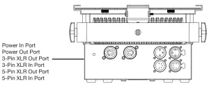
Data Cable (DMX Cable) Requirements (For DMX Operation): The 12PX Hex and 12PX Hex Pearl can be controlled via DMX-512 protocol. The 12PX Hex/12PX Hex Pearl has 4 DMX channel modes. The DMX address is set on the back panel of the 12PX Hex/12PX Hex Pearl. Your unit and your DMX controller require a standard 3-pin or 5-pin XLR connector for data input and data output (Figure 1). We recommend Accu-Cable DMX cables. If you are making your own cables, be sure to use standard 110-120 Ohm shielded cable (This cable may be purchased at almost all pro lighting stores). Your cables should be made with a male and female XLR connector on either end of the cable. Also remember that DMX cable must be daisy chained and cannot be split.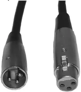 Figure 1
Notice: Be sure to follow figures two and three when making your own cables. Do not use the ground lug on the XLR connector. Do not connect the cable’s shield conductor to the ground lug or allow the shield conductor to come in contact with the XLR’s outer casing. Grounding the shield could cause a short circuit and erratic behavior.
 XLR Pin ConfigurationPin 1 = GroundPin 2 = Data Compliment (negative)Pin 3 = Data True (positive)
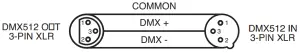
Special Note: Line Termination. When longer runs of cable are used, you may need to use a terminator on the last unit to avoid erratic behavior. A terminator is a 110-120 ohm 1/4 watt resistor which is connected between pins 2 and 3 of a male XLR connector (DATA + and DATA -). This unit is inserted in the female XLR connector of the last unit in your daisy chain to terminate the line. Using a cable terminator (ADJ part number Z-DMX/T) will decrease the possibilities of erratic behavior.
Termination reduces signal errors and avoids signal transmission problems and interference. It is always advisable to connect a DMX terminal, (Resistance 120 Ohm 1/4 W) between PIN 2 (DMX-) and PIN 3 (DMX +) of the last fixture
5-Pin XLR DMX Connectors. Some manufactures use 5-pin DMX-512 data cables for DATA transmission in place of 3-pin. 5-pin DMX fixtures may be implemented in a 3-pin DMX line. When inserting standard 5-pin data cables in to a 3-pin line a cable adaptor must be used, these adaptors are readily available at most electric stores. The chart below details a proper cable conversion.
|
3-Pin XLR to 5-Pin XLR Conversion |
||
|
Conductor |
3-Pin XLR Female (Out) | 5-Pin XLR Male (In) |
|
Ground/Shield |
Pin 1 |
Pin 1 |
| Data Compliment (- signal) |
Pin 2 |
Pin 2 |
| Data True (+ signal) | Pin 3 |
Pin 3 |
|
Not Used |
Do Not Use |
|
| Not Used |
Do Not Use |
DMX Addressing
All fixtures should be given a DMX starting address when using a DMX controller, so the correct fixture responds to the correct control signal. This digital starting address is the channel number from which the fixture starts to “listen” to the digital control signal sent out from the DMX controller. The assignment of this starting DMX address is achieved by setting the correct DMX address on the digital control display on the fixture.
You can set the same starting address for all fixtures or a group of fixtures, or set different addresses for each individual fixture. Setting all fixtures to the same DMX address will cause all fixtures to react in the same way, in other words, changing the settings of one channel will affect all the fixtures simultaneously.
If you set each fixture to a different DMX address, each unit will start to “listen” to the channel number you have set, based on the quantity of DMX channels of each fixture. That means changing the settings of one channel will only affect the selected fixture.
In the case of the 12PX Hex/12PX Hex Pearl, when in 12 channel mode you should set the starting DMX address of the first unit to 1, the second unit to 13 (12 + 1), the third unit to 25 (13 + 12), and so on. (See chart below for more details.)
|
Channel Mode |
Unit 1 Address | Unit 2 Address | Unit 3 Address | Unit 4 Address |
|
6 channels |
1 |
7 |
13 |
19 |
| 7 channels | 1 |
8 |
15 |
22 |
|
8 channels |
1 |
9 |
17 |
25 |
|
12 channels |
1 | 13 |
25 |
37 |
DMX Traits & Values
| 1 | 1 | I | 1 | 000.255 | Red 0-100% |
| 2 | 2 | 2 | 2 | 000-255 | Green 0-100% |
| 3 | 3 | 3 | 3 | 000 – 255 | Blue 0-100% |
| 4 | 0 | 4 | 4 | 000.255 | White 0-100% |
| 5 | 5 | 5 | 5 | 000 – 255 | Amber 0-100% |
| 6 | 6 | 6 | 6 | 000.255 | CAI 0-100% |
| 7 | 7 | 7 | 000 – 255 | Master Dimmer | |
| 8 | 8 | Strobe | |||
| 000 – 031 | LED off | ||||
| 032 – 053 | LED on | ||||
| 034 – 035 | Strobe. slaw to fast | ||||
| 096 – 127 | LED On | ||||
| 128 -159 | Pulse Strobe. slow to fast | ||||
| 169. | LE00n | ||||
| 192 – 223 | Random Strobe, slow to fast | ||||
| 224 – 255 | LED On | ||||
| 9 | 000 – 255 | Color Macros, see Color Macro Chart | |||
| 10 | Programs | ||||
| 030 – 020 | No function | ||||
| 021 – 04,0 | 30 Color Change | ||||
| Cal-COD | 6 Color Change | ||||
| 031 – 030 | Color Fade | ||||
| 081 – 100 | Sand Act.. 30 Coot Change | ||||
| 101 -120 | Sound Active 6 Cola change | ||||
| 121 – 140 | Sound Active 6 Color Fade | ||||
| 141 – 255 | No function | ||||
| 11 | Program Speed / Sensitivity | ||||
| 000 | No function | ||||
| COI – 255 | Spared Adjustment: low to last fatten Ch 10 a net to 021 – 060Sand Sensitivity. Mast to most Moan Cn 10 a aat to 081 – 140 | ||||
| 12 | Dim Mode | ||||
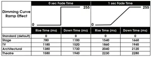
| 000 – 020 | Standard | ||||
| 021 – 040 | Stage | ||||
| WI – 060 | TV | ||||
| 031 – 080 | Architectural | ||||
| 031 -100 | Theatre | ||||
| 101 – 255 | Dimming Default to Display |
Color Macro Chart
| Color No. | DMX | RGBWA+UV COLOR INTENSITY | |||||
| VALUE | RED | GREEN | BLUE | WHITE | AMBER | UV | |
| OFF | 0 | 0 | 0 | 0 | 0 | 0 | 0 |
| Color1 | 4-Jan | 80 | 255 | 234 | 80 | 0 | 0 |
| Color2 | 8-May | 80 | 255 | 164 | 80 | 0 | 0 |
| Color3 | 12-Sep | 77 | 255 | 112 | 77 | 0 | 0 |
| Color4 | 13-16 | 117 | 255 | 83 | 83 | 0 | 0 |
| Color5 | 17-20 | 160 | 255 | 77 | 77 | 0 | 0 |
| Color6 | 21-24 | 223 | 255 | 83 | 83 | 0 | 0 |
| Color7 | 25-28 | 255 | 243 | 77 | 77 | 0 | 0 |
| Color8 | 29-32 | 255 | 200 | 74 | 74 | 0 | 0 |
| Color9 | 33-36 | 255 | 166 | 77 | 77 | 0 | 0 |
| Color10 | 37-40 | 255 | 125 | 74 | 74 | 0 | 0 |
| Color11 | 41-44 | 255 | 97 | 77 | 74 | 0 | 0 |
| Color12 | 45-48 | 255 | 71 | 77 | 71 | 0 | 0 |
| Color13 | 49-52 | 255 | 83 | 134 | 83 | 0 | 0 |
| Color14 | 53-56 | 255 | 93 | 182 | 93 | 0 | 0 |
| Color15 | 57-60 | 255 | 96 | 236 | 96 | 0 | 0 |
| Color16 | 61-64 | 238 | 93 | 255 | 93 | 0 | 0 |
| Color17 | 65-68 | 196 | 87 | 255 | 87 | 0 | 0 |
| Color18 | 69-72 | 150 | 90 | 255 | 90 | 0 | 0 |
| Color19 | 73-76 | 100 | 77 | 255 | 77 | 0 | 0 |
| Color20 | 77-80 | 77 | 100 | 255 | 77 | 0 | 0 |
| Color21 | 81-84 | 67 | 148 | 255 | 67 | 0 | 0 |
| Color22 | 85-88 | 77 | 195 | 255 | 77 | 0 | 0 |
| Color23 | 89-92 | 77 | 234 | 255 | 77 | 0 | 0 |
| Color24 | 93-96 | 158 | 255 | 144 | 144 | 0 | 0 |
| Color25 | 97-100 | 255 | 251 | 153 | 153 | 0 | 0 |
| Color26 | 101-104 | 255 | 175 | 147 | 147 | 0 | 0 |
| Color27 | 105-108 | 255 | 138 | 186 | 138 | 0 | 0 |
| Color28 | 109-112 | 255 | 147 | 251 | 147 | 0 | 0 |
| Color29 | 113-116 | 151 | 138 | 255 | 138 | 0 | 0 |
| Color30 | 117-120 | 100 | 138 | 255 | 138 | 0 | 0 |
| Color31 | 121-124 | 138 | 169 | 255 | 138 | 0 | 0 |
| Color32 | 125-128 | 255 | 255 | 255 | 255 | 0 | 0 |
| Color33 | 129-132 | 255 | 206 | 143 | 0 | 0 | 0 |
| Color34 | 133-136 | 254 | 177 | 153 | 0 | 0 | 0 |
| Color35 | 137-140 | 254 | 192 | 138 | 0 | 0 | 0 |
| Color36 | 141-144 | 254 | 165 | 98 | 0 | 0 | 0 |
| Color37 | 145-148 | 254 | 121 | 0 | 0 | 0 | 0 |
| Color38 | 149-152 | 176 | 17 | 0 | 0 | 0 | 0 |
| Color39 | 153-156 | 96 | 0 | 11 | 0 | 0 | 0 |
| Color40 | 157-160 | 234 | 139 | 171 | 0 | 0 | 0 |
| Color41 | 161-164 | 224 | 5 | 97 | 0 | 0 | 0 |
| Color42 | 165-168 | 175 | 77 | 173 | 0 | 0 | 0 |
| Color43 | 169-172 | 119 | 130 | 199 | 0 | 0 | 0 |
| Color44 | 173-176 | 147 | 164 | 212 | 0 | 0 | 0 |
| Color45 | 177-180 | 88 | 2 | 163 | 0 | 0 | 0 |
| Color46 | 181-184 | 0 | 38 | 86 | 0 | 0 | 0 |
| Color47 | 185-188 | 0 | 142 | 208 | 0 | 0 | 0 |
| Color48 | 189-192 | 52 | 148 | 209 | 0 | 0 | 0 |
| Color49 | 193-196 | 0 | 46 | 35 | 0 | 0 | 0 |
| Color50 | 197-200 | 8 | 107 | 222 | 0 | 0 | 0 |
| Color51 | 201-204 | 107 | 156 | 231 | 0 | 0 | 0 |
| Color52 | 205-208 | 165 | 198 | 247 | 0 | 0 | 0 |
| Color53 | 209-212 | 0 | 83 | 115 | 0 | 0 | 0 |
| Color54 | 213-216 | 0 | 97 | 166 | 0 | 0 | 0 |
| Color55 | 217-220 | 1 | 100 | 167 | 0 | 0 | 0 |
| Color56 | 221-224 | 0 | 40 | 86 | 0 | 0 | 0 |
| Color57 | 225-228 | 209 | 219 | 182 | 0 | 0 | 0 |
| Color58 | 229-232 | 42 | 165 | 85 | 0 | 0 | 0 |
| Color59 | 233-236 | 0 | 0 | 0 | 0 | 0 | |
| Color60 | 237-240 | 0 | 0 | 0 | 0 | 0 | 0 |
| Color61 | 241-244 | 255 | 0 | 0 | 0 | 0 | 0 |
| Color62 | 245-248 | 0 | 255 | 0 | 0 | 0 | 0 |
| Color63 | 249-252 | 0 | 0 | 255 | 0 | 255 | 0 |
| Color64 | 253-255 | 0 | 0 | 0 | 255 | 0 | 255 |
| MODE | ENTER | UP/DOWN | DESCRIPTION |
| DMX Control(displays selected optionfrom ENTER column) | A-xxx | 001 – 512 | Set DMX address |
| CH-xx | 08 | Select DMX channel mode | |
| 07 | |||
| 08 | |||
| 12 | |||
| dc-xx | 00 | Dimmer curve, standard | |
| 01 | Dimmer curve, stage | ||
| 02 | Dimmer curve, TV | ||
| 03 | Dimmer curve, architectural | ||
| 04 | Dimmer curve, theatre | ||
| DMX Lost (displays as selected option from UP/DOWN column) | Hold | Hold last when DMX signal is lost | |
| blc | Blackout fixture when DMX signal is lost | ||
| soun | Enter sound active mode when DMX signal is lost | ||
| Secondary Mode (Secd) | N/A | N/A | Set device in secondary mode |
| LED Refresh Rate Mode(F-xx) | N/A | 00 | 7 KHz LED refresh rate |
| 01 | 15 KHz LED refresh rate | ||
| Manual Mode(displays as selected op-tion from ENTER column) | R-xxx | 000 – 255 | Manual mode, red |
| G-xxx | 000 – 255 | Manual mode, green | |
| B-xxx | 000 – 255 | Manual mode, blue | |
| u-xxx | 000 – 255 | Manual mode, white | |
| A-xxx | 000 – 255 | Manual mode, amber | |
| U-xxx | 000 – 255 | Manual mode, UV | |
| Color Macros Mode (C-xx) | N/A | 01-64 | Select color macro, see color macro chart |
| Built-in Program Mode(displays as selected op-tion from ENTER column) | P-xx | 01 | Program: 63 color change/fade |
| 02 | Program: 63 color change (F invalid) | ||
| 03 | Program: 63 color fade | ||
| 04 | Program: 6 color change (F invalid) | ||
| 05 | Program: 6 color fade | ||
| 06 | Program: 63 color change + sound control (F and S invalid) | ||
| 07 | Program: 63 color change + sound (F and S invalid) | ||
| F-xx | 00 – 30 | Fade speed, fast to slow (default = 00) | |
| S-xx | 01 – 30 | Change speed, fast to slow (default = 01) | |
| RF Switch (RF-xx) | N/A | On / Off | RF switch on / off |
| Sound Sensitivity (So-xx) | N/A | 00 – 30 | Sound sensitivity setting (00 = ott) |
Operating Instructions
CONTROL PANEL LOCK: The control panel will lock itself after 30 seconds of inactivity. To unlock the control panel, press and hold the Mode button for 3 seconds.
DMX CONTROL MODE:
DMX Address
- Press the Mode button until one of the following is displayed: A-xxx, CH-xx, dc-xx, Hold, blc, or soun. These are the various options that are available in DMX Control Mode, and the option that is displayed is the last setting that was used.
- Press the Enter button until A-xxx is displayed. xxx represents a 3-digit DMX address of this device.
- Use the Up and Down buttons to adjust DMX address. Selectable numbers range from 001 to 512.
DMX Channel Mode
- Press the Mode button until one of the following is displayed: A-xxx, CH-xx, dc-xx, Hold, blc, or soun. These are the various options that are available in DMX Control Mode, and the option that is displayed is the last setting that was used.
- Press the Enter button until CH-xx is displayed. xx is a 2-digit number that represents the DMX channel mode.
- Use the Up and Down buttons to select the desired DMX channel mode. Options include 6-channel mode, 7-channel mode, 8-channel mode, and 12-channel mode.
Dimmer Curve
- Press the Mode button until one of the following is displayed: A-xxx, CH-xx, dc-xx, Hold, blc, or soun. These are the various options that are available in DMX Control Mode, and the option that is displayed is the last setting that was used.
- Press the Enter button until dc-xx is displayed. xx is a 2-digit number that represents the selected dimmer curve setting.
- Use the Up and Down buttons to select the desired dimmer curve setting. Selectable options include standard (00), stage (01), TV (02), architectural (03), and theatre (04).
DMX Lost
- Press the Mode button until one of the following is displayed: A-xxx, CH-xx, dc-xx, Hold, blc, or soun. These are the various options that are available in DMX Control Mode, and the option that is displayed is the last setting that was used.
- Press the Enter button until one of the following is displayed: Hold, blc, or soun. These are the available options to set up how the device will behave if the DMX signal is lost.
- Use the Up and Down buttons to select Hold, blc, or soun.
- Hold: The device will continue to operate according to the last settings that were received before the DMX connection was lost.
- blc: The device will black out when the DMX connection is lost.
- soun: The device will revert to sound active mode when DMX connection is lost.
SECONDARY MODE:
- Press the Mode button until Secd is displayed.
- The device is now in Secondary mode, and its behavior will follow the Primary device.
LED REFRESH RATE MODE:
- Press the Mode button until F-xx is displayed. xx is a 2-digit number the represents the selected LED refresh rate.
- Press the Up and Down buttons to select 7 KHz (00) or 15 KHz (01) as the desired LED refresh rate.
MANUAL MODE:
- Press the Mode button until one of the following is displayed: R-xxx, G-xxx, B xxx, u-xxx, A-xxx, or U-xxx. The letter represents the color option that was last selected, and xxx is a 3 digit number that represents the intensity setting that was last selected.
- Press the Enter button to cycle through the options listed below:
- R-xxx = Red
- G-xxx = Green
- B-xxx = Blue
- u-xxx = White
- A-xxx = Amber
- U-xxx = UV
- Press the Up and Down button to select the intensity level of the selected color. Selectable values range from 000 to 255.
COLOR MACROS MODE:
- Press the Mode button until C-xx is displayed. xx is a 2-digit number that represents the color macro that was last selected.
- Press the Up and Down button to select the desired color macro. Selectable values range from 01 to 64. Please see the Color Macros Chart section of this manual for a detailed list of color macros.
BUILT-IN PROGRAM MODE:
- Press the Mode button until one of the following is displayed: P-xx, F-xx, or S xx. The value displayed will depend on the option that was last selected.
- Press the Enter button until P-xx is displayed. Then use the Up and Down buttons to select the number of the desired program. Selectable values range from 01 to 07. Please refer to the System Menu section of this manual for descriptions of each program.
- Press the Enter button again until F-xx is displayed. Then use the Up and Down buttons to set the fade speed of the selected program, with 00 being the fastest setting and 30 being the slowest setting. Please note that fade speed is disabled for programs 02, 04, 06, and 07.
- Press the Enter button again until S-xx is displayed. Then use the Up and Down buttons to set the change speed of the selected program, with 01 being the fastest setting and 30 being the slowest setting. Please note the change speed is disabled for programs 06 and 07.
RF SWITCH:
- Press the Mode button until RF-xx is displayed. xx will be displayed as either “of” or “on”.
- Press the Up and Down button to select “of” or “on.”
- “of” disables the ability to control the device via remote control.
- “on” enables the ability to control the device via remote control.
SOUND SENSITIVITY:
- Press the Mode button until So-xx is displayed. xx is a 2-digit number that represents the sound sensitivity level that was last selected.
- Press the Up and Down button to scroll to the desired sound sensitivity level. Selectable values range from 00 to 30. Select 00 to turn sound sensitivty off.
Primary-Secondary Configuration
Primary-Secondary Configuration:
This function will allows you to link units together to run in a Primary-Secondary mode. In Primary-Secondary operation one unit will act as the controlling unit and the others will react to the controlling units built-in programs. Any unit can act as a Primary or as a Secondary however, only one unit can be programmed to act as the “Primary.”
Primary-Secondary Connections and Settings:
- Daisy chain your units via the XLR connector on the rear of the unit. Use standard XLR data cables to link your units together. Remember that the Male XLR connector is the input and the Female XLR connector is the ouput. The first unit in the chain (primary) will use the female XLR connector only. The last unit in the chain will use the male XLR connector only.
- Set the “Primary” unit to your desired mode of operation.
- Connect the first “Secondary” unit to the “Primary.”
- On the “Secondary” unit press the MODE button until “SECd” is displayed. The “Secondary” unit will now follow the “Primary”.
Dotz Par RF Operation
The Dotz Par RF remote (sold separately) has many different functions and allows you to control your fixture from long distance. The remote can control your system up to 25 meters. To use the remote you must first activate the fixtures receiver, to activate the receiver please see the instructions on page 17
BLACKOUT – Pressing this button will blackout the fixture.
FADE – This button will activate the fade program.
COLOR – This button will activate the static color mode. Use the “+” and “-” buttons to scroll through the colors and find your desired color.
PROGRAMS – This button will activate the built-in programs mode. Use the “+” and “-” buttons to scroll through the 7 programs and find your desired program.
SOUND ACTIVE – This button activates sound active mode.
AUTO RUN – When in program mode, press this button and use the “+” and “-” buttons to adjust the speed of the built-in programs. You can also use this button to activate program mode. “+” and “-” – Use these buttons to adjust the speed of the built-in program, scroll through the built-in programs, and scroll through the static colors.
Dimmer Curve Chart

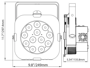
Dimensional Drawing
Multiple Unit Power Linking
With this feature you can connect the fixtures to one another using the power cable input and output sockets.
NOTE: USE CAUTION WHEN POWER LINKING OTHER FIXTURES AS THE POWER CONSUMPTION OF OTHER MODEL FIXTURES MAY EXCEED THE MAX POWER OUTPUT ON THIS FIXTURE! CHECK SILK SCREEN FOR MAX AMPS.
Trouble Shooting
Listed below are a few common problems the user may encounter, with solutions.
Unit not responding to DMX:
- Check that the DMX cables are connected properly and are wired correctly (pin 3 is “hot”; on some other DMX devices pin 2 may be ‘hot’). Also, check that all cables are connected to the right connectors; it does matter which way the inputs and outputs are connected.
Unit does not respond to sound:
- Quiet or high pitched sounds will not activate the unit.
- Make sure that Sound Active mode is activated.
Cleaning
Due to fog residue, smoke, and dust cleaning the internal and external optical lenses must be carried out periodically to optimize light output.
- Use normal glass cleaner and a soft cloth to wipe down the outside casing.
- Clean the external optics with glass cleaner and a soft cloth every 20 days.
- Always be sure to dry all parts completely before plugging the unit back in. Cleaning frequency depends on the environment in which the fixture operates (i.e. smoke, fog residue, dust, dew).
Specifications
Model: 12PX Hex/12PX Hex Pearl
- Voltage: 100V ~ 240V/50~60Hz
- LEDs: 12 x 12W 6-in-1 HEX LED’s
- Working Position: Any safe working position
- Power Draw: 133W
- Weight 8.7 lbs./ 4 Kgs.Dimensions: 5.34” (L) x 9.8” (W) x 11.7” (H) 135.8 x 249 x 297.4mm
- Colors RGBWA+UV Color Mixing
- DMX Channels: 4 DMX Modes: 6 Channel Mode,7 Channel Mode, 8 Channel Mode & 12 Channel Mode
- Warranty: 2 Year (730 days)
- Control: DMX, RDM (Remote Device Management), Sound Active, Manual
- Approvals / Ratings: ETL Approved / CE Certified
Please Note: Specifications and improvements in the design of this unit and this manual are subject to change without any prior written notice.
Warranty
MANUFACTURER’S LIMITED WARRANTY
- A. ADJ Products, LLC hereby warrants, to the original purchaser, ADJ Products, LLC products to be free of manufacturing defects in material and workmanship for a prescribed period from the date of purchase (see specific warranty period on reverse). This warranty shall be valid only if the product is purchased within the United States of America, including possessions and territories. It is the owner’s responsibility to establish the date and place of purchase by acceptable evidence, at the time service is sought.
- B. For warranty service you must obtain a Return Authorization number (RA#) before sending back the product–please contact ADJ Products, LLC Service Department at 800-322-6337. Send the product only to the ADJ Products, LLC factory. All shipping charges must be pre-paid. If the requested repairs or service (including parts replacement) are within the terms of this warranty, ADJ Products, LLC will pay return shipping charges only to a designated point within the United States. If the entire instrument is sent, it must be shipped in it’s original package. No accessories should be shipped with the product. If any accessories are shipped with the product, ADJ Products, LLC shall have no liability whatsoever for loss of or damage to any such accessories, nor for the safe return thereof.
- C. This warranty is void if the serial number has been altered or removed; if the product is modified in any manner which ADJ Products, LLC concludes, after inspection, affects the reliability of the product; if the product has been repaired or serviced by anyone other than the ADJ Products, LLC factory unless prior written authorization was issued to purchaser by ADJ Products, LLC; if the product is damaged because not properly maintained as set forth in the instruction manual.
- D. This is not a service contract, and this warranty does not include maintnance, cleaning or periodic check up. During the period specified above, ADJ Products, LLC will replace defective parts at its expense with new or refurbished parts, and will absorb all expenses for warranty service and repair labor by reason of defects in material or workmanship. The sole responsibility of ADJ Products, LLC under this warranty shall be limited to the repair of the product, or replacement thereof, including parts, at the sole discretion of ADJ Products, LLC. All products covered by this warranty were manufactured after August 15, 2012, and bear indentifying marks to that effect.
- E. ADJ Products, LLC reserves the right to make changes in design and/or improvements upon its products without any obligation to include these changes in any products theretofore manufactured.No warranty, whether expressed or implied, is given or made with respect to any accessory supplied with products described above. Except to the extent prohibited by applicable law, all implied warranties made by ADJ Products, LLC in connection with this product, including warranties of merchantability or fitness, are limited in duration to the warranty period set forth above. And no warranties, whether expressed or implied, including warranties of merchantability or fitness, shall apply to this product after said period has expired. The consumer’s and/or Dealer’s sole remedy shall be such repair or replacement as is expressly provided above; and under no circumstances shall ADJ Products, LLC be liable for any loss or damage, direct or consequential, arising out of the use of, or inability to use, this product.This warranty is the only written warranty applicable to ADJ Products, LLC Products and supersedes all prior warranties and written descriptions of warranty terms and conditions heretofore published.
MANUFACTURER’S LIMITED WARRANTY PERIODS:
- Non L.E.D. Lighting Products = 1-year (365 days) Limited Warranty (Such as: Special Effect Lighting, Intelligent Lighting, UV lighting, Strobes, Fog Machines, Bubble Machines, Mirror Balls, Par Cans, Trussing, Lighting Stands etc. excluding LED and lamps)
- Laser Products = 1 Year (365 Days) Limited Warranty (excluding laser diodes which have a 6 month limited warranty)
- L.E.D. Products = 2-year (730 days) Limited Warranty (excluding batteries which have a 180 day limited warranty). Note: 2 Year Warranty only applies to purchases within the United States.
- StarTec Series = 1 Year Limited Warranty (excluding batteries which have a 180 day limited warranty).
- ADJ DMX Controllers = 2 Year (730 Days) Limited Warranty
FCC STATEMENT
This device complies with Part 15 of the FCC Rules. Operation is subject to the following two conditions: (1) this device may not cause harmful interference, and (2) this device must accept any interference received, including interference that may cause undesired operation.
FCC RADIO FREQUENCY INTERFERENCE WARNINGS & INSTRUCTIONS
This product has been tested and found to comply with the limits as per Part 15 of the FCC Rules. These limits are designed to provide reasonable protection against harmful interference in a residential installation. This device uses and can radiate radio frequency energy and, if not installed and used in accordance with the included instructions, may cause harmful interference to radio communications. However, there is no guarantee that interference will not occur in a particular installation. If this device does cause harmful interference to radio or television reception, which can be determined by turning the device off and on, the user is encouraged to try to correct the interference by one or more of the following methods:
- Reorient or relocate the device.
- Increase the separation between the device and the receiver.
- Connect the device to an electrical outlet on a circuit different from which the radio receiver is connected.
- Consult the dealer or an experienced radio/TV technician for help.
ADJ Products, LLC6122 S. Eastern Ave. Los Angeles, CA 90040 USATel: 323-582-2650 / Fax: 323-582-2941www.adj.com
A.D.J. Supply Europe B.V.Junostraat 26468 EW KerkradeThe Netherlandswww.adj.eu
[email protected]Tel: +31 45 546 85 00Fax: +31 45 546 85 99
Follow us on:

 report this ad
facebook.com/americandjtwitter.com/americandjyoutube.com/adjlighting
[xyz-ips snippet=”download-snippet”]