![]()
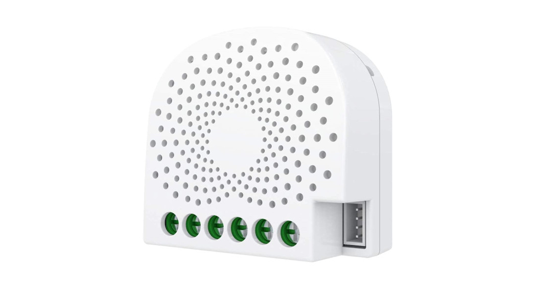
AeotecSingle Nano Switch with measuringSKU: AEOEZW116![]()
Quickstart
This is an On/Off Power Switch for Europe. To run this device please connect it to your mains power supply. following action:
- Install the device according to the instructions.
- Press the button 2 times quickly on the Nano Switch.
Important safety information
Please read this manual carefully. Failure to follow the recommendations in this manual may be dangerous or may distributor and seller shall not be liable for any loss or damage resulting from failure to comply with the instructions equipment only for its intended purpose. Follow the disposal instructions. Do not dispose of electronic equipment or
What is Z-Wave?Z-Wave is the international wireless protocol for communication in the Smart Home. This device is suited for use in Z-Wave ensures reliable communication by reconfirming every message (two-way communication) and every mains-powered node can act as a repeater for other nodes (meshed network) in case the receiver is not in direct wireless range of the transmitter.
This device and every other certified Z-Wave device can be used together with any other certified Z-Wave device regardless of brand and origin as long as both are suited for the same frequency range.
If a device supports secure communication it will communicate with other devices secure as long as this device provides the same or a higher level of security. Otherwise, it will automatically turn into a lower level of security to maintain backward compatibility.For more information about Z-Wave technology, devices, white papers etc. please refer to www.z-wave.info.
Product Description
Aeotec Nano Switch is a low-cost Z-Wave Switch specifically used to enable Z-Wave command and control (on/off wattage consumption or kWh energy usage over a period of time. In the event of power failure, non-volatile memory unit’s operating status.It can connect to 2 external manual switches to control the load ON/OFF independently. Its surface has a pin socket panel, so you can also use the touch panel to control the Nano Switch.The Nano Switch is also a security Z-Wave device and supports the Over The Air (OTA) feature for the products firmwa.
Prepare for Installation / Reset
Please read the user manual before installing the product.In order to include (add) a Z-Wave device to a network, it must be in the factory default state. Please make sure to re by performing an Exclusion operation as described below in the manual. Every Z-Wave controller is able to perform by performing an Exclusion operation as described below in the manual. Every Z-Wave controller is able to perform the primary controller of the previous network to make sure the very device is excluded properly from this network.Reset to factory defaultThis device also allows to be reset without any involvement of a Z-Wave controller. This procedure should only be uSet Parameter 255Safety Warning for Mains Powered DevicesATTENTION: only authorized technicians under consideration of the country-specific installation guidelines/norms ma assembly of the product, the voltage network has to be switched off and ensured against re-switching.
Installation
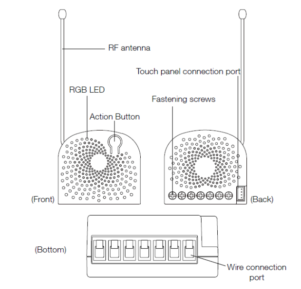
Notes for the wire connection ports:
N ? Power input for neutralL ? Power input for lifeIN? Input for load power supplyOUT1? Output for load 1OUT2? Output for load 2S1? External switch control for load 1S2? External switch control for load 2
- Shut off the main circuit breaker of your home for safety during the installation and ensure the wires are not short damage to the Nano Switch.Note: Your home’s main circuit breaker must support the overload protection for safety.
- Preparing connection wires 14 AWG power wires for Input/ Output. 18 AWG copper wires for external manual swathe connection wire and make sure the length of the metallic part is about 5mm.v All connection wires need to be flexible cable.
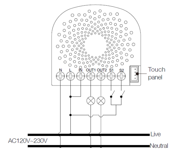
Wiring diagram of AC120V/230V power input.
In some cases, you may have some loads just only can be used on the voltage of DC24V and hope that it still can be the following diagram to achieve this:
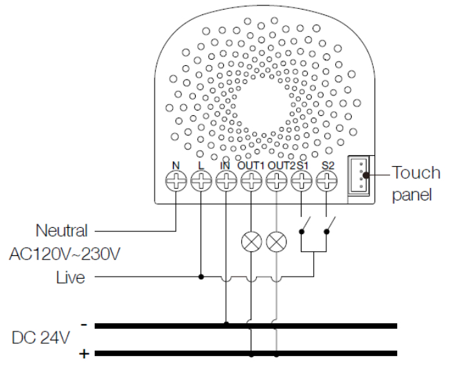
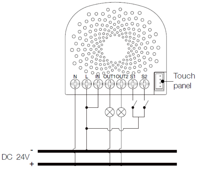
Wiring diagram of DC24V power input.Since the Nano Switch also supports the DC24V power input, so you can use it to control the loads powered by
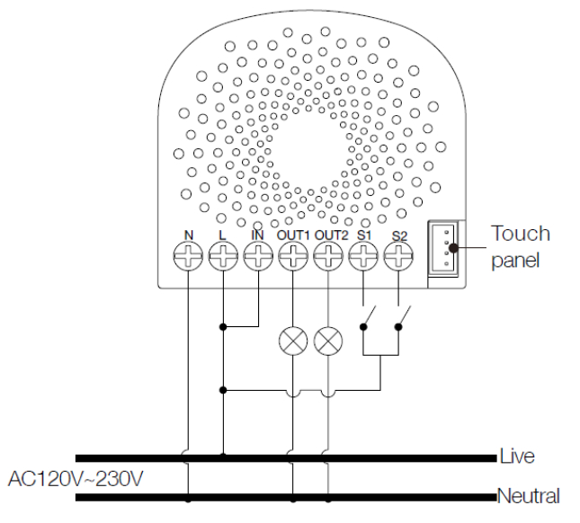
If the output loads should be only powered by AC120V or AC230V, you can change the wire connection as below:
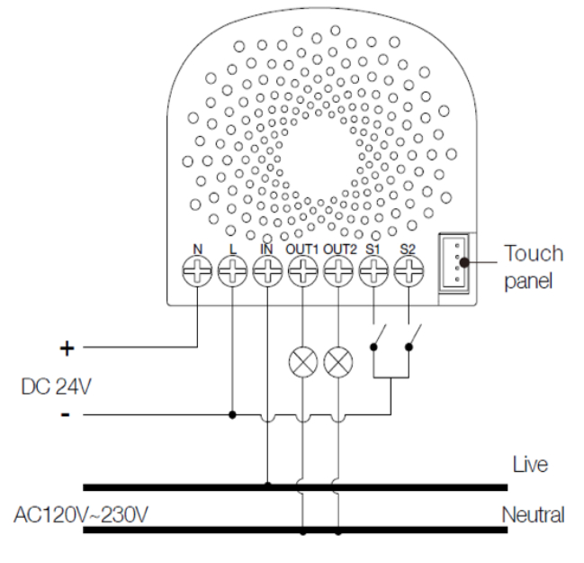
Note: The ?IN? terminal should be connected to the ? Live? of AC 120V/230V power wire.
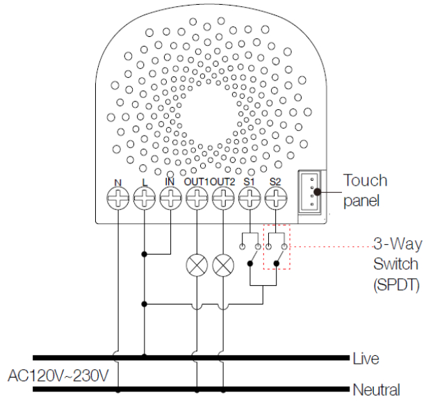
All above wiring diagrams show that the Nano Switch uses 2-Way or momentary button switches as the external ma diagram will show you that the Nano Switch uses the SPDT (Single-Pole Double-Throw) switches as the external ma
Wiring diagram of 3-Way connection for the external manual switch.
Inclusion/Exclusion
On factory default, the device does not belong to any Z-Wave network. The device needs to be added to the existing devices of this network. This process is called Inclusion.
Devices can also be removed from a network. This process is called Exclusion. Both processes are initiated by the controller is turned into exclusion respective inclusion mode. Inclusion and Exclusion is then performed doing a spe Inclusion
- Install the device according to the instructions.
- Press the button 2 times quickly on the Nano Switch.
Exclusion
- Press the button once on the Dual Nano Switch.
Quick troubleshooting
Here are a few hints for network installation if things dont work as expected.
- Make sure a device is in a factory reset state before including. In doubt exclude before include.
- If inclusion still fails, check if both devices use the same frequency.
- Remove all dead devices from associations. Otherwise you will see severe delays.
- Never use sleeping battery devices without a central controller.
- Don’t poll FLIRS devices.
- Make sure to have enough mains powered device to benefit from the meshing
Association – one device controls another device
Z-Wave devices control other Z-Wave devices. The relationship between one device controlling another device is a device, the controlling device needs to maintain a list of devices that will receive controlling commands. These lists are related to certain events (e.g. button pressed, sensor triggers, …). In case the event happens all devices are stored in tsame wireless command, typically a ‘Basic Set’ Command.
Association Groups:
| Group Number | MaximumNodes | Description |
| 1 | 5 | Z-Wave Plus Lifeline.When the load state of Nano Sw Multilevel Report and Basic Report (configured by pin this group. |
| 2 | 5 | Forward the Basic Set, Switch All, Scene Activation Nano Switch receives the Basic Set, Switch All, Sce |
| 3 | 5 | Send Basic Set (configured by parameter 82) to the switch S1 is operated |
| 4 | 5 | Send Basic Set (configured by parameter 82) to the switch S2 is operated |
Configuration Parameters
Z-Wave products are supposed to work out of the box after inclusion, however certain configuration can adapt the enhanced features.
IMPORTANT: Controllers may only allow configuring signed values. In order to set values in the range 128 … 255 value minus 256. For example: To set a parameter to 200 it may be needed to set a value of 200 minus 256 = minu applies: Values greater than 32768 may need to be given as negative values too.
Parameter 3: Current Overload Protection.Over-current protection. Output load will be closed after 30 seconds if the current exceeds (US: 15.5A, AU or EU: 1Size: 1 Byte, Default Value: 1
| Setting | Description |
| 0 | Disable |
| 1 | Enable |
Parameter 4: Overheat protection.Output Load will be turned off automatically after 30 seconds and if the temperature of product inside exceeds 100°Size: 1 Byte, Default Value: 0
| Setting | Description |
| 0 | Disable |
| 1 | Enable |
Parameter 20: Configure the output status after re-power on it.Configure the output status after re-power on it.Size: 1 Byte, Default Value: 0
| Setting | Description |
| 0 | Last status |
| 1 | Always on |
| 2 | Always off |
Parameter 80: To set which notification would be sent to the associated deviceTo set which notification would be sent to the associated devices (Group 1) when the state of Nano Dimmer’s load isSize: 1 Byte, Default Value: 0
| Setting | Description |
| 0 | Send Nothing |
| 1 | Send Hail CC |
| 2 | Send Basic CC report |
| 3 | Send Multilevel Switch report |
| 4 | Send Hail CC when using the manual switch to change the load |
Parameter 81: To set which notification would be sent to the associated nodesTo set which notification would be sent to the associated nodes in association Group 3 when using the external swiSize: 1 Byte, Default Value: 1
| Setting | Description |
| 0 | Send Nothing |
| 1 | Send Basic Set CC |
Parameter 82: To set which notification would be sent to the associated nodesTo set which notification would be sent to the associated nodes in association Group 4 when using the external swiSize: 1 Byte, Default Value: 1
| Setting | Description |
| 0 | Send Nothing |
| 1 | Send Basic Set CC |
Parameter 83: Configure the state of LEDConfigure the state of LED when it is in 3 modesSize: 1 Byte, Default Value: 0
| Setting | Description |
| 0 | The LED will follow the status (on/off) of its load (Energy mode). |
| 256 – 316 | The hour value of ON time |
| 2 | Night light mode. |
Parameter 84: ON/OFF timeSet the ON/OFF time of the LED when it is in Night light mode.Size: 4 Byte, Default Value: 524306
| Setting | Description |
| 0 – 60 | The minute time of OFF |
| 256 – 316 | The hour time of OFF |
| 65536 – 65596 | The minute time of ON |
| 16777216 – 16777276 | The hour time of ON |
Parameter 86: Set appointment 1Set appointment 1Size: 4 Byte, Default Value: 2293760
| Setting | Description |
| 0 – 60 | The minute value of ON time |
| 256 – 316 | The minute value of ON time |
| 65536 – 65543 | The day value (Mon to Sun) |
| 16777215 | Disable the setting. |
| 16777216 | Enable the setting. |
Parameter 87: Set appointment 2Set appointment 2Size: 4 Byte, Default Value: 2293760
| Setting | Description |
| 0 – 60 | The minute value of ON time |
| 256 – 316 | The hour value of ON time |
| 65536 – 65543 | The day value (Mon to Sun) |
| 16777215 | Disable the setting. |
| 16777216 | Enable the setting. |
Parameter 90: Enables/disables parameter 91 and 92 below:Enables/disables the function of parameters 91 and 92.Size: 1 Byte, Default Value: 0
| Setting | Description |
| 0 | Disable |
| 1 | Enable |
Parameter 91: Set the threshold value of wattage.Threshold change in wattage (in terms of wattage) to induce an automatic report.Size: 2 Byte, Default Value: 25
| Setting | Description |
| 0 – 60000 | The thershold value range is 0 to 60000 |
Parameter 92: Set the threshold value of wattage.Threshold change in wattage (in terms of percentage) to induce an automatic report.Size: 1 Byte, Default Value: 5
| Setting | Description |
| 0 – 100 | The thershold value range is 0 to 100 |
Parameter 100: Set parameter 101-103 to the default value.Set parameter 101-103 to the default value.Size: 1 Byte, Default Value: 0
| Setting | Description |
| 0 | Reset the parameter 101-103 |
Parameter 101: To set which reports need to be sent in Report group 1.To set which reports need to be sent in Report group 1.Size: 4 Byte, Default Value: 0
| Setting | Description |
| 1 | Send Meter Report of voltage (V) |
| 2 | Send Meter Report of current (A) |
| 4 | Send Meter Report of wattage (W) |
| 8 | Send Meter Report of energy (kWh) |
Parameter 102: To set which reports need to be sent in Report group 2.To set which reports need to be sent in Report group 2.Size: 1 Byte, Default Value: 0
| Setting | Description |
| 1 | Send Meter Report of voltage (V) |
| 2 | Send Meter Report of current (A) |
| 4 | Send Meter Report of wattage (W) |
| 8 | Send Meter Report of energy (kWh) |
Parameter 103: To set which reports need to be sent in Report group 3.To set which reports need to be sent in Report group 3.Size: 1 Byte, Default Value: 0
| Setting | Description |
| 1 | Send Meter Report of voltage (V) |
| 2 | Send Meter Report of current (A) |
| 4 | Send Meter Report of wattage (W) |
| 8 | Send Meter Report of energy (kWh) |
Parameter 110: Set parameter 111-113 to the default value.Set parameter 111-113 to the default value.Size: 1 Byte, Default Value: 0
| Setting | Description |
| 0 | Reset the parameter 111-113 |
Parameter 111: Set the interval of the automatic report for Report group 1.Set the interval of the automatic report for Report group 1.Size: 4 Byte, Default Value: 3
| Setting | Description |
| 1 – 2147483647 | The range of interval time is 1 to 2147483647. |
Parameter 112: Set the interval of the automatic report for Report group 2.Set the interval of the automatic report for Report group 2.Size: 4 Byte, Default Value: 600
| Setting | Description |
| 1 – 2147483647 | The range of interval time is 1 to 2147483647. |
Parameter 113: Set the interval of the automatic report for Report group 2.Set the interval of the automatic report for Report group 3.Size: 4 Byte, Default Value: 600
| Setting | Description |
| 1 – 2147483647 | The range of interval time is 1 to 2147483647. |
Parameter 120: Configure the external switch mode for S1.Configure the external switch mode for S1.Size: 1 Byte, Default Value: 0
| Setting | Description |
| 0 | Enter automatic identification mode |
| 1 | Momentary push button mode |
| 2 | 3-way switch mode |
| 3 | 2-state switch mode |
Parameter 121: Configure the external switch mode for S2.Configure the external switch mode for S2.Size: 1 Byte, Default Value: 0
| Setting | Description |
| 0 | Enter automatic identification mode |
| 1 | Momentary push button mode |
| 2 | 3-way switch mode |
| 3 | 2-state switch mode |
Parameter 122: Set the control destination for external switch S1Set the control destination of the external switch.Size: 1 Byte, Default Value: 3
| Setting | Description |
| 1 | control the output loads of itself. |
| 2 | control the other nodes |
| 3 | control the output loads of itself and other nodes. |
Parameter 252: Lock/unlock configuration parametersLock/unlock configuration parameters.Size: 1 Byte, Default Value: 0
| Setting | Description |
| 0 | Unlock |
| 1 | Lock |
Parameter 255: Reset the Nano DimmerReset the Nano Dimmer to factory default.Size: 4 Byte, Default Value: 0c
| Setting | Description |
| 0 | Reset all configuration parameters to the factory default setting |
| 1.43E+09 | Reset to factory default setting and removed from the z-wave net |
Technical Data
| Dimensions | 0.0425000×0.0400000×0.0200000 mm |
| Weight | 28.5 gr |
| Hardware Platform | ZM5202 |
| EAN | 1.22E+12 |
| IP Class | IP 20 |
| Voltage | 24V DC/ 230V AC |
| Load | 6,5 A |
| Device Type | On/Off Power Switch |
| Generic Device Class | Binary Switch |
| Specific Device Class | Binary Power Switch |
| Firmware Version | 1 |
| Z-Wave Version | 4.22 |
| Certification ID | ZC10-17035496 |
| Z-Wave Product Id | 0x0086.0x0003.0x0074 |
| Frequency | Europe – 868,4 Mhz |
| Maximum transmission power | 5 mW |
Supported Command Classes
| Basic | Configuration |
| Switch Binary | Alarm |
| Switch All | Manufacturer Specific |
| Scene Activation | Powerlevel |
| Scene Actuator Conf | Firmware Update Md |
| Meter | Clock |
| Association Grp Info | Association |
| Device Reset Locally | Version |
| Zwaveplus Info | Hail |
Controlled Command Classes
- Hail
 report this ad
Explanation of Z-Wave specific terms
- Controller — is a Z-Wave device with capabilities to manage the network. Controllers are typically Gateways, controllers.
- Slave — is a Z-Wave device without capabilities to manage the network. Slaves can be sensors, actuators and
- Primary Controller — is the central organizer of the network. It must be a controller. There can be only one prima
- Inclusion — is the process of adding new Z-Wave devices into a network.
- Exclusion — is the process of removing Z-Wave devices from the network.
- Association — is a control relationship between a controlling device and a controlled device.
- Wakeup Notification — is a special wireless message issued by a Z-Wave device to announces that is able to
- Node Information Frame — is a special wireless message issued by a Z-Wave device to announce its capability
(c) 2020 Z-Wave Europe GmbH, Antonstr. 3, 09337 Hohenstein-Ernstthal, Germany, All rights reserved, www.zwave.eu.Europe GmbH. The product content is maintained by Z-Wave Europe GmbH, Support team, [email protected]. Last upda
http://manual.zwave.eu/backend/make.php?lang=en&sku=AEOEZW116
References
[xyz-ips snippet=”download-snippet”]