![]()
![]()
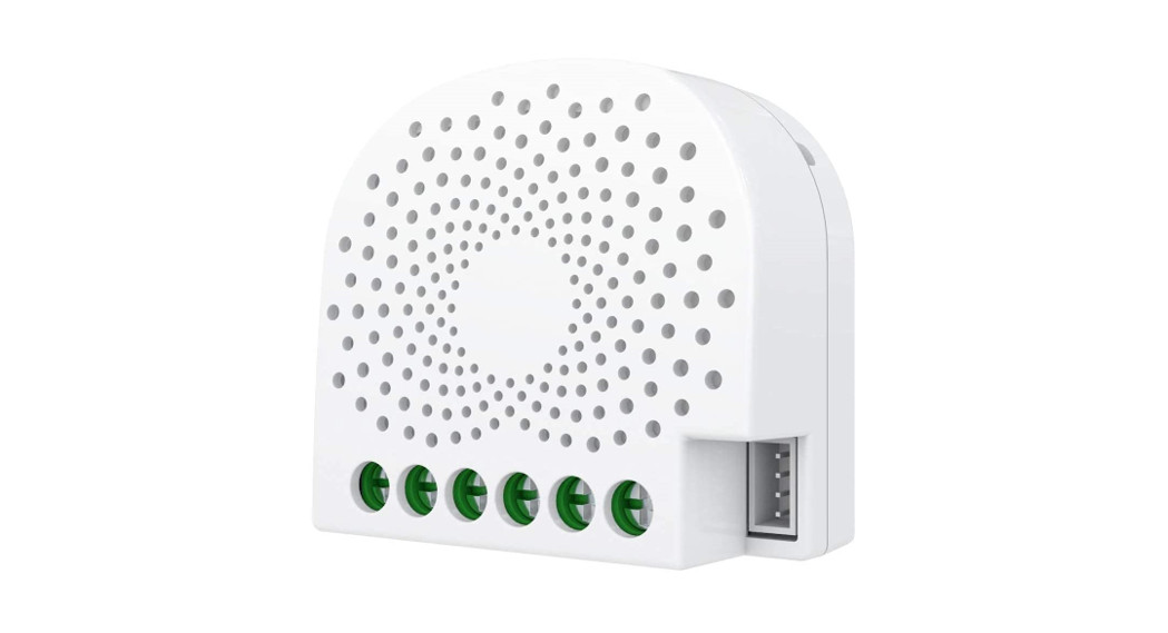
AEOTEC – Nano ShutterSKU: AEOEZW141
![]()
QuickstartThis is a secure Roller Shutter for Europe. To run this device please connect it to your mains power supply.
- Install your Nano Shutter.
- Scan the QR code on Nano Shutter using your Z-Wave gateway/controllers app.
- Power On your Nano Shutter
- Your Nano Shutter will automatically pair to your Z-Wave network.
Important safety information
Please read this manual carefully. Failure to follow the recommendations in this manual may be dangerous or may violate the law. The manufacturer, importer, distributor, and seller shall not be liable for any loss or damage resulting from failure to comply with the instructions in this manual or any other material. Use this equipment only for its intended purpose. Follow the disposal instructions. Do not dispose of electronic equipment or batteries in a fire or near open heat sources.
What is Z-Wave?
Z-Wave is the international wireless protocol for communication in the Smart Home. This device is suited for use in the region mentioned in the Quickstart sectionZ-Wave ensures a reliable communication by reconfirming every message (two-way communication) and every mains-powered node can act as a repeater for other nodes (meshed network) in case the receiver is not in direct wireless range of the transmitter.![]()
This device and every other certified Z-Wave device can be used together with any other certified Z-Wave device regardless of brand and origin as long as both are suited for the same frequency range.If a device supports secure communication it will communicate with other devices secure as long as this device provides the same or a higher level of security. Otherwise, it will automatically turn into a lower level of security to maintain backward compatibility.For more information about Z-Wave technology, devices, white papers, etc. please refer to www.z-wave.info
Product Description
Aeon Labs Nano Shutter is a Z-Wave power binary switch device based on Z-Wave enhanced 232 slave library V6.71.01. Its surface has a pin socket, which can be used for connecting to the touch panel, so you can also use the touch panel to control the Nano Shutter. It can also be included and operated in any Z-Wave netw with other Z-Wave certified devices from other manufacturers and/or other applications. All non-battery-operated nodes within the network will act as repeaters regardless of the vendor to increase the reliability of the network. It is a security Z-Wave plus device, so a security-enabled controller is needed to take full advan of all functionally for the Nano Shutter. It also supports the Over The Air (OTA) feature for the product?s firmware upgrade. As soon as Nano Shutter is removed Z-Wave network it will be restored into default factory setting.NEW: This device supports Smart Start and Positioning as well as Venetian -Mode
Prepare for Installation / Reset
Please read the user manual before installing the product.In order to include (add) a Z-Wave device to a network, it must be in the factory default state. Please make sure to reset the device into factory default. You can do by performing an Exclusion operation as described below in the manual. Every Z-Wave controller is able to perform this operation however it is recommended to the primary controller of the previous network to make sure the very device is excluded properly from this network.
Reset to factory defaultThis device also allows being reset without any involvement of a Z-Wave controller. This procedure should only be used when the primary controller is inoperable Press the Action Button for 20 secondsSafety Warning for Mains Powered DevicesATTENTION: only authorized technicians under consideration of the country-specific installation guidelines/norms may do works with mains power. Prior to the assembly of the product, the voltage network has to be switched off and ensured against re-switching.
Installation
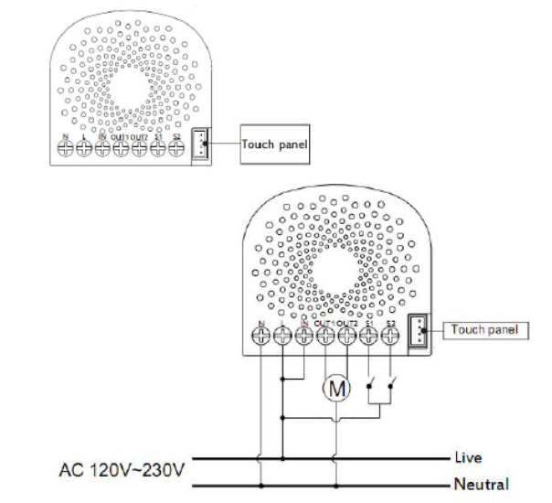
Notes for the wire connection ports:N – Power input for neutralL – Power input for lifeIN – Input for load power supplyOUT1 – Output for Motor direction 1 (Down)OUT2 – Output for Motor direction 2 (UP)S1 – External switch 1 control for Motor (UP)S2 – External switch 2 control for Motor (DOWN)
Inclusion/Exclusion
On factory default, the device does not belong to any Z-Wave network. The device needs to be added to an existing wireless network to communicate with the devices of this network. This process is called Inclusion.Devices can also be removed from a network. This process is called Exclusion. Both processes are initiated by the primary controller of the Z-Wave network. the controller is turned into exclusion respective inclusion mode. Inclusion and Exclusion is then performed doing a special manual action right on the device.Inclusion
- Install the device according to the instructions.
- Press the button on the Nano Shutter once.
Exclusion
- Press the button on the Nano Shutter 6 times.
Product Usage
Calibration of Nano Shutter (V 3.0 and later)Calibration for Shutter has 2 modes: Shutter Mode and Venetian Mode.In Shutter mode, only the Current Trip Time (Parameter 35) is used for up/down control.In Venetian Mode, the Curtain Trip Time (Parameter 35) and Blade Turn Time (Parameter 34) are used for up/down control and angle of rotation of the leaf
Shutter ModeUsed for standard roller blinds that move up and down only.
The calibration process is as follows:
- Enter calibration mode• By short pressing 3 times (Z-Wave button or external switch)• Or by sending a CONFIGURATION SET Parameter 36 [1 byte] to value 1.
- The curtain will begin to move to the end in one direction (fully open or fully closed); reference point A.• Press the Action Button/S1/S2 once the curtain is at max open or close to telling Nano Shutter to perform the next step.
- The motor/curtain will reverse to another direction; reference point B.• Press the Action Button/S1/S2 once the current is at the max open or close to finalize the calibration.
- Calibration is completed.• Nano Shutter records the run time from the reference point A to B, which is the time between max open and the max close of the curtain (this time can be read and modified through the Configuration 0x23 (35) if additional readjustments are needed).
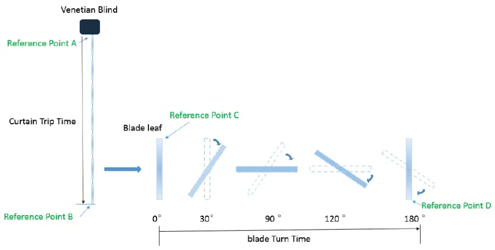
Venetian Mode
Nano Shutter in Venetian Mode can be set to open the blinds up/down, as well as the angle of rotation of the leaf separately. There is a switch on Venetian to change the Controlling Channel for blind lifting and leaf rotation, the switch needs manual operation by the user.The calibration process is as follows:
- Before calibration, set the Venetian to blind lifting channel; [Paramter 38 to value 1]
- Enter Venetian calibration mode by:• By short pressing 5 times (Z-Wave button or external switch)• Or by sending a CONFIGURATION SET Parameter 36 [1 byte] to value 2.
- The motor connected to Nano Shutter should move toward the direction in which the blinds are curled upwards (Reference C).• Once the blinds are fully opened and curled upwards completely (Reference A and C):• Press the Action Button/S1/S2 once to calibrate Reference A.• If the blinds are unfolded, the motor movement direction needs to be reset by setting Parameter 22 to value 2; after setting the correct direction follow step a to re-enter the calibration mode (step a);
- Nano Shutter should now reverse the direction the motor blind movement downwards (Towards reference B). Once blinds close up completely (Reference point B):• Press the Action Button/S1/S2 once to calibrate Reference B.
- Nano Shutter will stop working and require that the Venetian blinds must be set to leaf rotation channel;• Press the Action Button/S1/S2 once to start leaf rotation calibration.
- The Venetian blinds should begin leaf rotation, the window leaf turn to 0° (reference point C).• Press the Action Button/S1/S2 once the leaf is rotated completely.
- The Venetian blinds will rotate to 180° (Reference point D).• Press the Action Button/S1/S2 once the leaf is rotated completely to finalize calibration.
- The Nano Shutter records the run time between points A and B, and turn time between reference points C and D which are curtain trip time and blad turn time (the recorded time can be read and modified from the Configuration 0x22 (34) and 0x23 (35)).
Operation Mode 1. – Split reaction between S1 and S2 controls.
|
External Switch 1 (S1) |
External Switch 2 (S2) |
|||||
| Current State. | Stop | Moving to 100% | Moving to 0% | Stop | Moving to 0% | Moving to 100% |
| Button pressed once. | Move to 100% | Stop | NC | Move to 0% | Stop | NC |
Operation Mode 2. – Same controls over S1 and S2.
|
External Switch 1 + 2 (S1 and S2 |
|||||
| Current State | At 0% | Moving to 0% | Moving to 100% | At 100% | Stop |
| Button pressed once | Move to 100% | Stop | Stop | Move to 0% | Toggle |
The function of Action ButtonClick one time
- Send out Node info.
- Add Nano Shutter into a Z-Wave network:1. Power on your Nano Shutter, the RGB LED will be colorful gradient status.2. Let the primary controller into inclusion mode (If you don?t know how to do this, refer to its manual).3. Press the Action button.4. If the inclusion is successful, the LED will be solid. Otherwise, the LED will remain colorful gradient status, in which you need to repeat the process from st
Quick press 2 timesActivate the automatic identification mode for external switch S1.The blue LED will fast blink to indicate the Nano Shutter is in this mode.Note: When the Nano Shutter enters this mode, toggle the external switch S1 once and wait 2 seconds for the Nano Shutter to detect the external switch type of
Quick press 3 timesEnter Shutter Calibration ModeOrange light flashing when calibrating.
- Press the Button/S1/S2 once when blinds arrive at max close.
- Press the Button/S1/S2 again when blinds arrive at max open.
- LED will stop when calibration is done.
Quick press 4 timesThe green LED will fast blink to indicate the Nano Shutter is in this mode.Note: When the Nano Shutter enters this mode, toggle the external switch S2 once and wait 2 seconds for the Nano Shutter to detect the external switch type of
Quick press 5 timesEnter Venetian Calibration ModeWhite light flashing when calibrating.
Quick press 6 times
- Send out Node info.
- Remove Nano Shutter from a Z-Wave network:1. Power on your Nano Shutter, the LED will be solid.2. Let the primary controller into remove mode (If you don t know how to do this, refer to its manual).3. Quick press the Action button 6 times.4. If the removal is successful, the LED will be colorful gradient status. If the LED is still solid, please repeat the process from step 2.
Press and hold 20 secondsReset Nano Shutter to factory default:
- Make sure the Nano Shutter has been powered on.
- Press and hold the Action Button for 20 seconds.
- The green LED will be on for 2 seconds and then remain colorful gradient status, which indicates the reset is successful, otherwise please repeat from step 2.
Note:
- This procedure should only be used when the primary controller is missing or inoperable.
- Reset the Nano Shutter to factory default will exclude the Nano Shutter from the Z-Wave network, clear the Association settings, Scene configuration settings, and restore the Configuration settings to the default.
Central Scene Notification (V3.0 and higher)Switch 1
Key Pressed 1 timeKey Pressed 2 timesKey held Down (Push Button Supported Only)Key Released (Push Button Supported Only)
Switch 2
Key Pressed 1 timeKey Pressed 2 timesKey held Down (Push Button Supported Only)Key Released (Push Button Supported Only)Note: Only Push Button mode switch support Attribut Key Held Down/Key Released
Node Information Frame
The Node Information Frame (NIF) is the business card of a Z-Wave device. It contains information about the device type and the technical capabilities. The inclu and exclusion of the device is confirmed by sending out a Node Information Frame. Beside this it may be needed for certain network operations to send out a No Information Frame. To issue a NIF execute the following action: Press the Action Button one time.
Quick troubleshooting
Here are a few hints for network installation if things dont work as expected.
- Make sure a device is in factory reset state before including. In doubt exclude before include.
- If inclusion still fails, check if both devices use the same frequency.
- Remove all dead devices from associations. Otherwise, you will see severe delays.
- Never use sleeping battery devices without a central controller.
- Dont poll FLIRS devices.
- Make sure to have enough mains powered device to benefit from the meshing
Association – one device controls another device
Z-Wave devices control other Z-Wave devices. The relationship between one device controlling another device is called association. In order to control a different device, the controlling device needs to maintain a list of devices that will receive controlling commands. These lists are called association groups and they are alw related to certain events (e.g. button pressed, sensor triggers, …). In case the event happens all devices stored in the respective association group will receive the same wireless command, typically a ‘Basic Set’ Command.
Association Groups:
| Group Number | MaximumNodes | Description |
| 1 | 5 | Lifeline |
| 2 | 5 | Forward the Basic Set, Binary set, Scene Activation Set to associated nodes in Group 2 when tNano Shutter receives the Basic Set, Binary set, Scene Activation Set commands. |
Configuration Parameters
Z-Wave products are supposed to work out of the box after inclusion, however, certain configuration can adapt the function better to user needs or unlock further enhanced features.IMPORTANT: Controllers may only allow configuring signed values. In order to set values in the range 128 … 255 the value sent in the application shall be the devalue minus 256. For example: To set a parameter to 200 it may be needed to set a value of 200 minus 256 = minus 56. In the case of a two-byte value, the same log applies: Values greater than 32768 may be needed to be given as negative values too.
Parameter 20: Motor behavior after Power ON (V3.0 and later)Size: 1 Byte, Default Value: 0
| Setting | Description |
| 0 | Stay the same position before power off last time. |
| 1 | Moves to 99% |
| 2 | Moves to 0% |
Parameter 22: Determine motor run direction (V3.0 and later)Change the mapping of output and motor running direction between the 2 directions below:na. Out1 maps forward and Out2 maps reverse. Out1 maps reverse Out2 maps forwardSize: 1 Byte, Default Value: 2
| Setting | Description |
| 2 | Change direction |
Parameter 34: Blade Turn Time (V3.0 and later)Note: For Venetian, if this value is set too large for blade turning, the curtain may move upwards or downwards. Calibration needs to work correctly. Or this setting will the curtain to move up or down.nThis configuration will not change after network exclusion or Configuration Reset.Size: 2 Byte, Default Value: 150
| Setting | Description |
| 10 – 32767 | Configurable Range (0,1 – 327675 seconds) |
Parameter 35: Curtain Trip Time (V3.00 and later)Note: For Venetian, if this value is set too large for curtain trip, blade turn positioning may cause errors. This configuration will not change after the network exclusioConfiguration Reset.Size: 2 Byte, Default Value: 15000
| Setting | Description |
| 500 – 32767 | Configurable Range (5 – 327675 seconds) |
Parameter 35: Moving time (up to version 2.2)Set the moving time from up (left) to down (right) for curtain.Size: 1 Byte, Default Value: 30
| Setting | Description |
| 1 – 255 | Moving time |
Parameter 36: Enter/Exit Calibration (V3.0 and later)Note: Product will enter the right Curtain Mode after calibration, see Configuration 0x27Size: 1 Byte, Default Value: 0
| Setting | Description |
| 0 | Set:Exit Calibration Report: Not in Calibration |
| 1 | Set: Enter Shutter Mode Calibration Report: In Shutter Mode Calibration |
| 2 | Set:Enter Venetian Mode Cal ibration Report: In Venetian Mode Calibration |
Parameter 37: User confirmation for calibration (V3.0 and later)Size: 1 Byte, Default Value: 1
| Setting | Description |
| 1 | Go to the next step of calibration |
Parameter 38: Return Calibration Status (Get or Report) (V3.0 and later)Size: 1 Byte, Default Value: 0
| Setting | Description |
| 0 | Calibration Complete |
| 1 | Calibration starts, going to Reference Point A |
| 2 | Reach Reference Point A, going to Reference Point B |
| 3 | Reach Reference Point B, waiting for Blade turn Calibration(Only for Venetian Mode) |
| 4 | Going to Reference Point C(Only for Venetian Mode) |
| 5 | Calibration terminated |
Parameter 39: Set the Curtain Mode (V3.0 and later)Note: 1. This Operation will enter repositioning automatically;n2. This configuration will not change after network exclusion or Configuration Reset.Size: 1 Byte, Default Value: 0
| Setting | Description |
| 0 | Shutter Mode |
| 1 | Venetian Mode |
Parameter 40: Set repositioning begins (V3.0 and later)Size: 1 Byte, Default Value: 1
| Setting | Description |
| 1 | Repositioning begins |
Parameter 41: Get repositioning Status (V3.0 and later)Size: 1 Byte, Default Value: 0
| Setting | Description |
| 0 | Repositioning complete |
| 1 | In repositioning |
Parameter 42: Calibration Lock.Used to enable/disable calibration lock (V3.0 and later)Size: 1 Byte, Default Value: 1
| Setting | Description |
| 0 | Disable calibration |
| 1 | Enable Action Button/ Command Calibration |
| 2 | Enable Action Button/ Command/S1/S2 Calibration |
Parameter 80: Report to group 1To set which report would be sent to the associated nodes in association group 1 when the state of the output load is changed.Size: 1 Byte, Default Value: 0
| Setting | Description |
| 0 | Nothing |
| 1 | Basic Report CC |
| 2 | Switch Multilevel Report (V3.0 and later) |
Parameter 85: Operation mode of an external switchSet the operation mode of an external switch. Operation Mode 1: Used S1 for close and S2 for opening the blind Operation Mode 2: Used both buttons for the same aSize: 1 Byte, Default Value: 0
| Setting | Description |
| 0 | Operation Mode 1 |
| 1 | Operation Mode 2 |
Parameter 120: Type of S1Set the external switch mode of S1Size: 1 Byte, Default Value: 0
| Setting | Description |
| 0 | Unidentified mode. |
| 2 | 3-way switch mode |
| 3 | Push-button mode |
| 4 | Enter automatic identification mode (The blue Led will fast blink). |
Parameter 121: Type of S2Set the external switch mode of S2Size: 1 Byte, Default Value: 0
| Setting | Description |
| 0 | Unidentified mode |
| 2 | 3 way switch mode |
| 3 | push button mode |
| 4 | enter automatic identification mode (The green Led will fast blink). |
Parameter 248: Enable/Disable function of External Switch S1&S2 (V3.0 and later)Note: This value can be combined, e.g. set to 3(1+2=3), which means the networking function and Reset function are both enabled.Size: 1 Byte, Default Value: 1
| Setting | Description |
| 1 | Enable network function, inclusion/exclusion |
| 2 | Enable reset to factory default function |
Parameter 251: Enable/Disable function of External Touch Panel (V3.0 and later)Enable/disable reset to factory default and exclusion function by long press on touch panel and press 6 times on wall swipeSize: 1 Byte, Default Value: 1
| Setting | Description |
| 0 | Disable |
Parameter 252: Enable/disable the configuration parameters to be locked. (up to version 2.2)Size: 1 Byte, Default Value: 0
| Setting | Description |
| 0 | disabel |
| 1 | enable |
 report this ad
Parameter 255: Factory resetSize: 4 Byte, Default Value:
| Setting | Description |
| 1431655765 | Factory Reset |
| 0 | Reset all configuration parameters to factory default settings |
Technical Data
| Dimensions | 0.0425000×0.0400000×0.0200000 mm |
| Weight | 34.24 gr |
| Hardware Platform | ZM5101 |
| EAN | 1.22E+12 |
| IP Class | IP 20 |
| Voltage | 230V |
| Load | 10A |
| Device Type | Roller Shutter |
| Generic Device Class | Multilevel Switch |
| Specific Device Class | Motor Control Device (A) |
| Firmware Version | 3 |
| Z-Wave Version | 6.81 |
| Certification ID | ZC10-18066132 |
| Z-Wave Product Id | 0x0371.0x0003.0x008d |
| Frequency | Europe – 868,4 Mhz |
| Maximum transmission power | 5 mW |
Supported Command Classes
| Basic | Configuration |
| Switch Binary | Manufacturer Specific |
| Switch Multilevel | Powerlevel |
| Scene Activation | Firmware Update Md |
| Scene Actuator Conf | Association |
| Association Grp Info | Version |
| Device Reset Locally | Security |
| Zwaveplus Info | Transport Service |
| Supervision | Security 2 |
Controlled Command Classes
- Transport Service
- Security 2
Explanation of Z-Wave specific terms
- Controller — is a Z-Wave device with capabilities to manage the network. Controllers are typically Gateways,Remote
- Controls or battery-operated wall controllers.
- Slave — is a Z-Wave device without capabilities to manage the network. Slaves can be sensors, actuators and even remote controls.
- Primary Controller — is the central organizer of the network. It must be a controller. There can be only one primary controller in a Z-Wave network.
- Inclusion — is the process of adding new Z-Wave devices into a network.
- Exclusion — is the process of removing Z-Wave devices from the network.
- Association — is a control relationship between a controlling device and a controlled device.
- Wakeup Notification — is a special wireless message issued by a Z-Wave device to announces that is able to communicate.
- Node Information Frame — is a special wireless message issued by a Z-Wave device to announce its capabilities and functions.
(c) 2020 Z-Wave Europe GmbH, Antonstr. 3, 09337 Hohenstein-Ernstthal, Germany, All rights reserved, www.zwave.eu. The template is maintained by Z-Wave Europe GmbH. The product content is maintained by Z-Wave Europe GmbH , Supportteam, [email protected]. Last update of the product data: 2020-01-23
http://manual.zwave.eu/backend/make.php?lang=en&sku=AEOEZW141
References
[xyz-ips snippet=”download-snippet”]