
AeoTec Door / Window Sensor 7 Pro User Guide
Quick start
This is a secure Alarm Sensor for Europe. To run this device please insert fresh 1 * 1/2 AA batteries. Please make sure the internal battery is fully charged. The DSK for the S2 inclusion can be found inside the sensors packaging.
If your Z-Wave gateway supports SmartStart: scan the QR code on Door / Window Sensor 7 Pro using the gateway’s app. Your sensor will join your Z-Wave network automatically.
Important safety information
Please read this manual carefully. Failure to follow the recommendations in this manual may be dangerous or may violate the law. The manufacturer, importer, distributor and seller shall not be liable for any loss or damage resulting from failure to comply with the instructions in this manual or any other material. Use this equipment only for its intended purpose. Follow the disposal instructions. Do not dispose of electronic equipment or batteries in a fire or near open heat sources.
What is Z-Wave?
![]() Z-Wave is the international wireless protocol for communication in the Smart Home. This device is suited for use in the region mentioned in the Quickstart section.
Z-Wave is the international wireless protocol for communication in the Smart Home. This device is suited for use in the region mentioned in the Quickstart section.
Z-Wave ensures a reliable communication by reconfirming every message (two-way communication) and every mains powered node can act as a repeater for other nodes (meshed network) in case the receiver is not in direct wireless range of the transmitter.
This device and every other certified Z-Wave device can be used together with any other certified Z-Wave device regardless of brand and origin as long as both are suited for the same frequency range.
If a device supports secure communication it will communicate with other devices secure as long as this device provides the same or a higher level of security. Otherwise it will automatically turn into a lower level of security to maintain backward compatibility.
SmartStart. Available in selected Z-Wave Plus devices built upon 500 series technology and all devices built upon 700 series technology, SmartStart lets you setup Z-Wave devices in seconds. Using SmartStart enabled apps, simply scan the QR code on any compatible app to connect it to your Z-Wave gateway.
For more information about Z-Wave technology, devices, white papers etc. please refer to www.z-wave.info.
Product Description
The AEOTEC Door/Window Sensor 7 Pro is a sensor, which detects if your window is opened, closed or tilted. The sensor is easily retrofittable. Furthermore, the AEOTEC Door/Window Sensor can include other sensors by being connected with other binary sensors like NTC contacts, microswitches or flood sensors.
Thanks to its slim design the AEOTEC Door/Window Sensor 7 Pro can be installed unflashy on every window. The sensor just has to be installed on the window casement. Additionally, there has to be a slim magnet installed closely to the sensor at the window frame. By using a patented method the sensor can reliably detect the exact position of the window.
With the potential free input, the Door/Window Sensor can also include other sensors in your Z-Wave system. For that, the binary sensor is connected to the potential free input of the sensor. Besides sensors, there can also be connected momentary switches, which control scenes in your gateway.
Tripple clicking the tamper button includes (adds) and excludes (removes) the device. A single click on the button will wake up the device. The device supports the Z-Wave Security S2 framework with authenticated and unauthenticated network keys. Please follow the instructions on the central controller when including. The device also supports SmartStart.
Prepare for Installation / Reset
Please read the user manual before installing the product.
In order to include (add) a Z-Wave device to a network it must be in factory default state. Please make sure to reset the device into factory default. You can do this by performing an Exclusion operation as described below in the manual. Every Z-Wave controller is able to perform this operation however it is recommended to use the primary controller of the previous network to make sure the very device is excluded properly from this network.
Reset to factory defaultThis device also allows to be reset without any involvement of a Z-Wave controller. This procedure should only be used when the primary controller is inoperable.
Once Cover is removed and the tamper switch is tripped, push the tamper for 5 seconds until the RED LED blinks once. Then release tamper and push it again for 5 seconds while the RED LED is blinking until the GREEN LED blinks once.
Safety Warning for BatteriesThe product contains batteries. Please remove the batteries when the device is not used. Do not mix batteries of different charging level or different brands.
Installation
The sensor can be mounted either on the moving part or on the fixed part of a door or a window. Mounting can be accomplished either using the tape by peeling off the protection foil or using two screws with the holes inside the battery compartment. If the tilt detection on a window (only normal windows, no roof windows) shall be used the sensor device must be placed on the moving part of the window and the magnet on the window frame.
The sensor comes with two types of magnets:
- The standard magnet covered by plastic part, mountable beside the sensor. Make sure the two indicating lines on sensor enclosure and magnet are opposite to each other. The image on the right-hand side shows the position of magnet and sensor body.
- A slim naked magnet to be mounted behind the sensor in case the sensor body is placed on the side of a window.
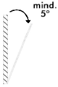
- To use the tilting function, the opening angle of the window must be at least 5°.


For German-style windows where the window sits on top of the window frame mounting on the side of the window is highly recommended. If no tilting detection is used, the sensor can be placed on any position of the door or the window. In case tilting detection is desired the sensor should be placed on the upper side of the window.
Inclusion/Exclusion
On factory default the device does not belong to any Z-Wave network. The device needs to be added to an existing wireless network to communicate with the devices of this network. This process is called Inclusion.
Devices can also be removed from a network. This process is called Exclusion. Both processes are initiated by the primary controller of the Z-Wave network. This controller is turned into exclusion respective inclusion mode. Inclusion and Exclusion is then performed doing a special manual action right on the device.
Inclusion1. Open the housing.2. Remove the battery protection.3. Press the tamper on the side of the appliance three times quickly.
Exclusion1. Open the housing.2. Press the tamper on the side of the appliance three times quickly.
Product Usage
Once installed the sensor will report “open” and “close” status changes to a central Z-Wave controller using notification commands. Additionally, the sensor can directly control other devices using association group 2. Using configuration commands the source of “open” and “close” events can be chosen between the internal magnet detector or external dry contact connected via the screw terminal. The device is protected by a tamper switch.
Tilt detection
The tilt detection allows reporting the way a window is opened. This is accomplished using the command class “binary sensor – tilt-type”. In case the window is closed or opened without tilting the tilt sensor will report “Off”. In case the window is tilted an “On” is reported. The angle of inclination of the window must be at least 5°.
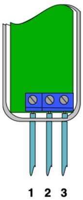
Screw Terminal
The product must support the interconnection of external binary sensors as well as actuators and drycontacts. The product allows interconnection with external sensors/actuators via 3-pin screw terminals with the following pinout:
• #1: Ground• #2: Digital Input• #3: VCC (direct battery supply)
VCC + Ground terminals can be used to externally power the sensor with a 3.6V battery or special power adapter (which is not included in the scope of delivery). Digital + VCC is used to connect the external dry contact.
Link testing
When activated by configuration parameter #5 the device can perform a link test with device No.1. Doubleclicking the tamper will start the process. As a result, the GREEN LED will blink two times in case of success and the RED LED will blink two times in case of failure.
Scene Controller
When activated by configuration parameter #14 the device can perform as a scene controller. Digital + VCC is used to connect the scene button. The external dry contact will then act as a scene controller with a total of 7 scenes that can be activated:
· 1 – Contact Pressed 1 time· 2 – Contact Pressed 2 time· 3 – Contact Pressed 3 time· 4 – Contact Pressed 4 time· 5 – Contact Pressed 5 time· 6 – Contact held down· 7 – Contact released
The device sends the following notifications to the central controller:
· Window Opened(0x06 – 0x16)· Window Closed(0x06 – 0x17)· Tamper Removed(0x07 – 0x03)
The device sends the following sensor binary reports to the controller:· Tilt(0x0B)
Node Information Frame
The Node Information Frame (NIF) is the business card of a Z-Wave device. It contains information about the device type and the technical capabilities. The inclusion and exclusion of the device is confirmed by sending out a Node Information Frame. Beside this it may be needed for certain network operations to send out a Node Information Frame. To issue a NIF execute the following action: Press the tamper once
Quick trouble shooting
Here are a few hints for network installation if things don’t work as expected.
- Make sure a device is in factory reset state before including. In doubt exclude before include.
- If inclusion still fails, check if both devices use the same frequency.
- Remove all dead devices from associations. Otherwise you will see severe delays.
- Never use sleeping battery devices without a central controller.
- Don’t poll FLIRS devices.
- Make sure to have enough mains powered device to benefit from the meshing
Firmware-Update over the Air
This device is capable of receiving a new firmware ‘over the air’. The update function needs to be supported by the central controller. Once the controller starts the update process, perform the following action to confirm the firmware update: Wake Up the device by removing the cover. Then hit the tamper switch once.
Association – one device controls an other device
Z-Wave devices control other Z-Wave devices. The relationship between one device controlling another device is called association. In order to control a different device, the controlling device needs to maintain a list of devices that will receive controlling commands. These lists are called association groups and they are always related to certain events (e.g. button pressed, sensor triggers, …). In case the event happens all devices stored in the respective association group will receive the same wireless command wireless command, typically a ‘Basic Set’ Command.
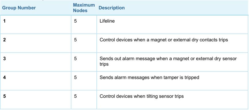
Association Groups:
Configuration Parameters
Z-Wave products are supposed to work out of the box after inclusion, however certain configuration can adapt the function better to user needs or unlock further enhanced features.
IMPORTANT: Controllers may only allow configuring signed values. In order to set values in the range 128 … 255 the value sent in the application shall be the desired value minus 256. For example: To set a parameter to 200it may be needed to set a value of 200 minus 256 = minus 56. In case of a two byte value the same logic applies: Values greater than 32768 may needed to be given as negative values too.
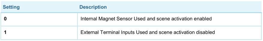
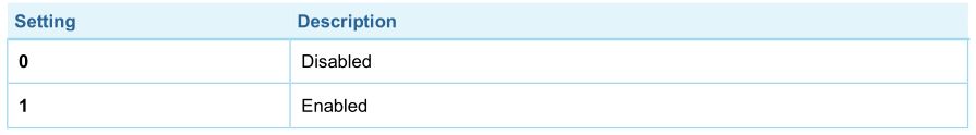
Parameter 1: Sensor Operation ModeThis parameter defines if the internal magnet sensor or the external terminal input is detected and used to issue alarm notification. The other sensor input the deactivated. If the parameter is set to 1, the scene activation for the external terminal input will be deactivated. Size: 1 Byte, Default Value: 0
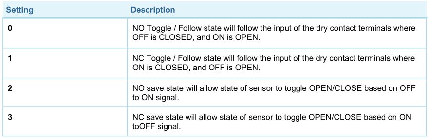
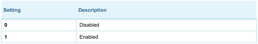
Parameter 2: Dry Contact Operation ModeParameter defines how dry contact will operate with the sensor or switch that is connected to the dry contact terminals. Size: 1 Byte, Default Value: 0
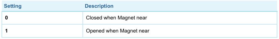
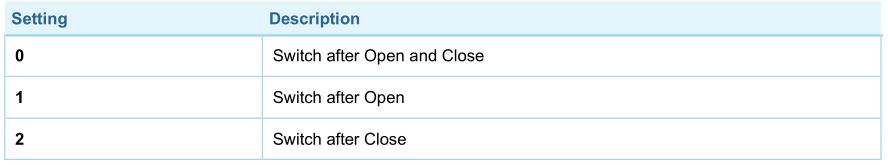
Parameter 3: Door/window stateThis parameter allows to set in what state is door/window when the magnet is close to the sensor. Size: 1 Byte, Default Value: 0
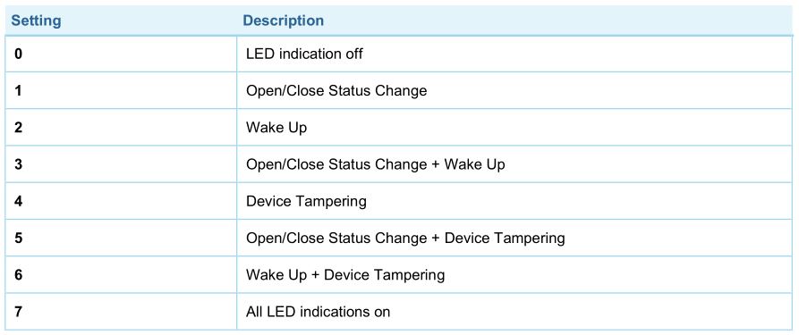
Parameter 4: Visual LED IndicationsThis parameter defines when the red LED will indicate events. Disabling all indications may extend battery life. Value 0 means no indications. Size: 1 Byte, Default Value: 7 (values 1 + 2 + 4 summarized)
Parameter 5: Range Test after double clickAllows to enable the activation of a Z-Wave range test. Double-clicking the tamper will start the process. As a result, the GREEN LED will blink two times in case of success and the RED LED will blink two times in case of failure. Size: 1 Byte, Default Value: 0
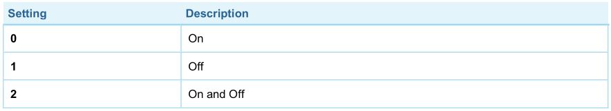
Parameter 6: 2nd Association Group TriggerThis parameter defines the status of the magnet switch that causes sending a BASIC command to all devices of Association Group 2. Size: 1 Byte, Default Value: 0
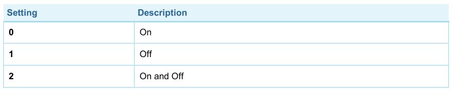
Parameter 7: Command Sent to Devices of Association Group 2This parameter defines which commands is sent to 2nd Association Group Size: 1 Byte, Default Value: 2
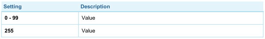
Parameter 8: BASIC command value sent to 2nd Association Group on On eventThis is the BASIC command value sent in case of On event. Size: 1 Byte, Default Value: 255
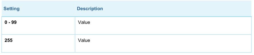
Parameter 9: BASIC command value sent to 2nd Association Group on Off eventThis is the BASIC command value sent in case of Off event. Size: 1 Byte, Default Value: 0

Parameter 10: Time Delay of On command frameOn command is sent after a delay defined in this parameter. Size: 2 Byte, Default Value: 0

Parameter 11: Time Delay of Off command frameOff command is sent after a delay defined in this parameter. Size: 2 Byte, Default Value: 0

Parameter 12: Delay of Tamper Alarm CancellationTime a tamper alarm is delayed. Size: 2 Byte, Default Value: 0

Parameter 13: Reporting Tamper Alarm CancellationThis parameter defines if the alarm cancellation event is reported. Size: 1 Byte, Default Value: 1

Parameter 14: Central Scene Event FunctionalityThis parameter enables/disables the central scene function. Size: 1 Byte, Default Value: 1
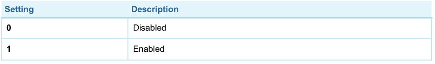
Parameter 15: Tilt Sensor FunctionalityThis parameter enables/disables the tilt function. Size: 1 Byte, Default Value: 1
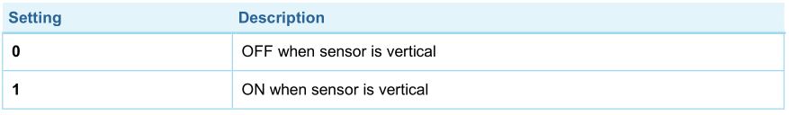
Parameter 16: Tilt Sensor StateThis parameter allows to set in what state is door/window when the tilt is in an OFF state. Size: 1 Byte, Default Value: 0
Parameter 17: 5th Association Group TriggerThis parameter defines the status of the magnet switch that causes sending a BASIC command to all devices of Association Group 5. Size: 1 Byte, Default Value: 0

Parameter 18: Command Sent to Devices of Association Group 5This parameter defines which commands is sent to 5th Association Group Size: 1 Byte, Default Value: 2
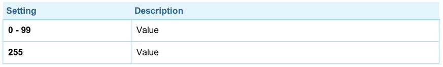
Parameter 19: BASIC command value sent to 5th Association Group on On eventThis is the BASIC command value sent in case of On event. Size: 1 Byte, Default Value: 255
Parameter 20: BASIC command value sent to 5th Association Group on Off eventThis is the BASIC command value sent in case of Off event. Size: 1 Byte, Default Value: 0
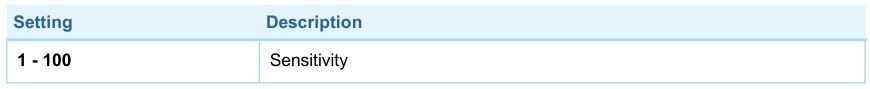
Parameter 21: Tilt sensitivityWith this parameter, you can adjust the tilt sensitivity if the tilt is too low or too strong. Value 0 does not disable Tilt Sensor, it just sets it to a minimum. Size: 1 Byte, Default Value: 50
Parameter 255: Reset Parameter This parameter helps reset configuration parameters and the device to factory defaults Size: 4 Byte, Default Value: 0

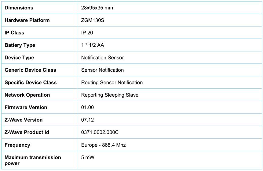
Technical Data
Supported Command Classes
- Configuration Command Class, Version 4 (highest granted security level)
- Multilevel Sensor Command Class, Version 11 (highest granted security level)
- Multi Channel Association Command Class, Version 3 (highest granted security level)
- Association Group Information Command Class, Version 3 (highest granted security level)
- Device Reset Locally Command Class, Version 1 (highest granted security level)
- Z-Wave Plus Info Command Class, Version 2 (non-Secure)
- Notification Command Class, Version 8 (highest granted security level)
- Manufacturer Specific Command Class, Version 2 (highest granted security level)
- Powerlevel Command Class, Version 1 (highest granted security level)
- Firmware Update Meta Data Command Class, Version 5 (highest granted security level)
- Battery Command Class, Version 1 (highest granted security level)
- Wake Up Command Class, Version 2 (highest granted security level)
- Indicator Command Class, Version 3 (highest granted security level)
- Association Command Class, Version 2 (highest granted security level)
- Version Command Class, Version 3 (highest granted security level)
- Security 2 Command Class, Version 1 (highest granted security level)
- Supervision Command Class, Version 1 (non-Secure)
- Transport Service Command Class, Version 2 (non-Secure)
- Central Scene Command Class, Version 3 (highest granted security level)
Explanation of Z-Wave specific terms
- Controller — is a Z-Wave device with capabilities to manage the network. Controllers are typically Gateways, Remote Controls or battery operated wall controllers.
- Slave — is a Z-Wave device without capabilities to manage the network. Slaves can be sensors, actuators and even remote controls.
- Primary Controller — is the central organizer of the network. It must be a controller. There can be only one primary controller in a Z-Wave network.
- Inclusion — is the process of adding new Z-Wave devices into a network.
- Exclusion — is the process of removing Z-Wave devices from the network.
- Association — is a control relationship between a controlling device and a controlled device.
- Wakeup Notification — is a special wireless message issued by a Z-Wave device to announces that is able to communicate.
- Node Information Frame — is a special wireless message issued by a Z-Wave device to announce its capabilities and functions.
References
[xyz-ips snippet=”download-snippet”]