
Aeon Labs
Home Energy Meter (C3 60A)
SKU: AEOEZW095C3A60
![]()
QuickstartThis is a Smart Meter for Europe. To run this device please connect it to your mains power supply. To add this device to your network execute the following action:– Push the button on backside
Important safety informationPlease read this manual carefully. Failure to follow the recommendations in this manual may be dangerous or may violate the law. The manufacturer, importer, distributor and seller shall not be liable for any loss or damage resulting from failure to comply with the instructions in this manual or any other material. Use this equipment only for its intended purpose. Follow the disposal instructions. Do not dispose of electronic equipment or batteries in a fire or near open heat sources.
What is Z-Wave?Z-Wave is the international wireless protocol for communication in the Smart Home. This device is suited for use in the region mentioned in the Quickstart section.
Z-Wave ensures a reliable communication by reconfirming every message (two-way communication) and every mains powered node can act as a repeater for other nodes (meshed network) in case the receiver is not in direct wireless range of the transmitter.
This device and every other certified Z-Wave device can be used together with any other certified ZWave device regardless of brand and origin as long as both are suited for the same frequency range.
If a device supports secure communication it will communicate with other devices secure as long as this device provides the same or a higher level of security. Otherwise it will automatically turn into a lower level of security to maintain backward compatibility.
For more information about Z-Wave technology, devices, white papers etc. please refer to www.z-wave.info.

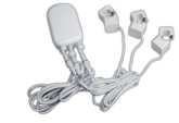
Product DescriptionInstalled in an electricity box, the energy meter will monitor the total consumption of electricity used by an entire building. And its intelligent clamps will report that energy use back to your Z-Wave gateway or controller, in watts or kilowatt-hours, and in real time. So you can see how much electricity you really use and when you use it.
Prepare for Installation / ResetPlease read the user manual before installing the product.
In order to include (add) a Z-Wave device to a network it must be in factory default state. Please make sure to reset the device into factory default. You can do this by performing an Exclusion operation as described below in the manual. Every Z-Wave controller is able to perform this operation however it is recommended to use the primary controller of the previous network to make sure the very device is excluded properly from this network.
Reset to factory defaultThis device also allows to be reset without any involvement of a Z-Wave controller. This procedure should only be used when the primary controller is inoperable.
– Press and hold the button on the backside for 10 seconds
Safety Warning for Mains Powered DevicesATTENTION: only authorized technicians under consideration of the country-specific installation guidelines/norms may do works with mains power. Prior to the assembly of the product, the voltage network has to be switched off and ensured against re-switching.
Installation
Unless otherwise stated, the circuit box’s main breaker should be turned off to perform these installation steps.
- Turn the main breaker off.
- Open the main circuit box panel.
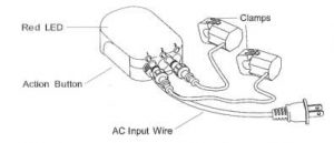
- Clip one clamp of the meter around the incoming electricity cable that connects to the main circuit breaker.
- Connect the clamp to the meter using a Clamp Connector.
- Connect the AC Wire to the meter using the AC Wire Connector.
- Wire the AC Wire into one breaker. The brown wire is Live, the blue wire is neutral.
- Replace the main circuit box panel.
- Turn the main breaker back on.
It is now time to place the main body of the Home Energy Meter. Inside the meter is a radio antenna used for communications, and this must be taken into consideration when selecting a location for the meter.
If the circuit boxes is made of metal the radio signal strength may be reduced. In this situation it is recommended that the main body of the meter be affixed outside the circuit box. This will improve the radio signal strength. The Home Energy Meter has been weatherized to the international IP43 standard so that it is resistant to rain and snow when placed vertically with the wires protruding from the bottom of the unit.
To place the Home Energy Meter:
- Unslot the backing plate from the back of your meter.
- Affix the plate to the selected wall space using the provided screws.
- Attach your meter to the backing plate.
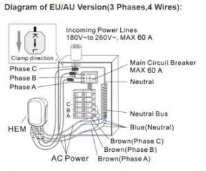
Diagram of EU/AU Version (3 Phases, 4 Wires):
Inclusion/ExclusionOn factory default the device does not belong to any Z-Wave network. The device needs to be added to an existing wireless network to communicate with the devices of this network. This process is called Inclusion.
Devices can also be removed from a network. This process is called Exclusion. Both processes are initiated by the primary controller of the Z-Wave network. This controller is turned into exclusion respective inclusion mode. Inclusion and Exclusion is then performed doing a special manual action right on the device.
Inclusion– Push the button on backside
Exclusion– Push the button three times on backside
Product UsageSetting Parameter 101 -103
| Byte# | DecimalValue | Output | Clamp# | HEMRestriction |
| byte 4 | 1 | kWh | TotalReadings | |
| byte 4 | 2 | Watt | TotalReadings | |
| byte 4 | 4 | Voltage | TotalReadings | |
| byte 4 | 8 | Amperage | TotalReadings | |
| byte 4 | 16 | kVarh | TotalReadings | Gen5Only |
| byte 4 | 32 | kVar | TotalReadings | Gen5Only |
| byte 4 | 64 | Reserved | ||
| byte 4 | 128 | Reserved | ||
| byte 3 | 256 | Watt | Clamp 1 | |
| byte 3 | 512 | Watt | Clamp 2 | |
| byte 3 | 1024 | Watt | Clamp 3 | |
| byte 3 | 2048 | kWh | Clamp 1 | |
| byte 3 | 4096 | kWh | Clamp 2 | |
| byte 3 | 8192 | kWh | Clamp 3 | |
| byte 3 | 16384 | Reserved | ||
| byte 3 | 32768 | Reserved | ||
| byte 2 | 65536 | Voltage | Clamp 1 | |
| byte 2 | 131072 | Voltage | Clamp 2 | |
| byte 2 | 262144 | Voltage | Clamp 3 | |
| byte 2 | 524288 | Amperage | Clamp 1 | |
| byte 2 | 1048576 | Amperage | Clamp 2 | |
| byte 2 | 2097152 | Amperage | Clamp 3 | |
| byte 2 | 4194304 | Reserved | ||
| byte 2 | 8388608 | Reserved | ||
| byte 1 | 16777216 | kVah | Clamp 1 | Gen5Only |
| byte 1 | 33554432 | kVah | Clamp 2 | Gen5Only |
| byte 1 | 67108864 | kVah | Clamp 3 | Gen5Only |
| byte 1 | 134217728 | kVar | Clamp 1 | Gen5Only |
| byte 1 | 268435456 | kVar | Clamp 2 | Gen5Only |
| byte 1 | 536870912 | kVar | Clamp 3 | Gen5Only |
| byte 1 | 1073741824 | Reserved | ||
| byte 1 | 2147483648 | Reserved |
Quick trouble shootingHere are a few hints for network installation if things dont work as expected.
- Make sure a device is in factory reset state before including. In doubt exclude before include.
- If inclusion still fails, check if both devices use the same frequency.
- Remove all dead devices from associations. Otherwise you will see severe delays.
- Never use sleeping battery devices without a central controller.
- Dont poll FLIRS devices.
- Make sure to have enough mains powered device to benefit from the meshing
Association – one device controls an other device
Z-Wave devices control other Z-Wave devices The relationship between one device controlling another device is called association In order to control a different always related to certain events (e.g. button pressed, sensor triggers, …). In case the event happens all devices stored in the respective association group will receive the same wireless command wireless command, typically a ‘Basic Set’ Command.
Association Groups:
| GroupNumber | MaximumNodes | Description |
| 1 | 5 | Send configured Value to devices |
| 2 | 5 | Send configured Value to devices |
| 3 | 5 | Send configured Value to devices |
Configuration ParametersZ-Wave products are supposed to work out of the box after inclusion, however certain configuration can adapt the function better to user needs or unlock further enhanced features.
IMPORTANT: Controllers may only allow configuring signed values. In order to set values in the range 128 … 255 the value sent in the application shall be the desired value minus 256. For example: To set a parameter to 200 it may be needed to set a value of 200 minus 256 = minus 56. In case of a two byte value the same logic applies: Values greater than 32768 may needed to be given as negative values too.
Parameter 2: Energy detection modeFor parameters of 101, power, energy detection modeSize: 1 Byte, Default Value: 0
| Setting | Description |
| 0 | report power, energy absolute value |
| 1 | report positive/negative power, report the algebraic sum energy |
| 2 | report positive/negative power, only report energypositive part (consuming electricity) |
| 3 | report positive/negative power, only report energynegative part (generating electricity) |
Parameter 3: Selective reportingEnable selective reporting only when power change reaches a certain threshold or percentage set in 4-11 below. This is used to reduce network traffic. Size: 1 Byte, Default Value: 1
| Setting | Description |
| 0 | disable |
| 1 | enable |
Parameter 4: Threshold change in wattageThreshold change in wattage to induce a automatic report (Whole HEM).Size: 2 Byte, Default Value: 50
Setting Description 0 – 60000 Watt
Parameter 5: Threshold change in wattage (Clamp 1)Threshold change in wattage to induce a automatic reportSize: 2 Byte, Default Value: 50
Setting Description0 – 100 Valid value
Parameter 6: Threshold change in wattage (Clamp 2)Threshold change in wattage to induce a automatic reportSize: 2 Byte, Default Value: 50
Setting Description0 – 100 Valid value
Parameter 7: Threshold change in wattage (Clamp 3)Threshold change in wattage to induce a automatic reportSize: 2 Byte, Default Value: 50
Setting Description0 – 100 Valid value
Parameter 8: Percentage change in wattage (Whole HEM)Percentage change in wattage to induce a automatic reportSize: 1 Byte, Default Value: 10
Setting Description
Parameter 9: Percentage change in wattage (Clamp 1)Percentage change in wattage to induce a automatic reportSize: 1 Byte, Default Value: 10
Setting Description0 – 100 Valid value
Parameter 10: Percentage change in wattage (Clamp 2)Percentage change in wattage to induce a automatic reportSize: 1 Byte, Default Value: 10
Setting Description0 – 100 Valid value
Parameter 11: Percentage change in wattage (Clamp 3)Percentage change in wattage to induce a automatic reportSize: 1 Byte, Default Value: 10
Setting Description0 – 100 Valid value
Parameter 13: Enable /disable reportingEnable /disable reporting CRC-16 Encapsulation CommandSize: 1 Byte, Default Value: 0
| Setting | Description |
| 0 | disable |
| 1 | enable |
Parameter 100: Reset parameter 101-103Size: 1 Byte, Default Value: 0
Setting Description1 reset parameter 101-103
Parameter 101: Setting automatic report flags Group 1Example: 1 + 1024 = Value 1025 If you want to report everthing, you would add the whole table together and set in to 101.Please, see table in usage.Size: 4 Byte, Default Value: 0
Setting Description1 Report Total HEM – KWH2 Report Total HEM – Watt4 Report Total HEM – Voltage8 Report Total HEM – Current
Parameter 102: Setting automatic report flags Group 2Example: 1 + 1024 Value 1025 If you want to report everthing you would add the whole table together and set in to 102
Setting Description1 Report Total HEM – KWH2 Report Total HEM – Watt4 Report Total HEM – Voltage8 Report Total HEM – Current
Parameter 103: Setting automatic report flags Group 3Example: 1 + 1024 = Value 1025 If you want to report everthing, you would add the whole table together and set in to 103.Please, see table in usage.Size: 4 Byte, Default Value: 0
Setting Description1 Report Total HEM – KWH2 Report Total HEM – Watt4 Report Total HEM – Voltage8 Report Total HEM – Current
Parameter 110: Reset parameter 111-113
Size: 1 Byte, Default Value: 0
Setting Description1 reset parameter 111-113
Parameter 111: Setting an automatic report intervalSet the report intervall for Group 1Size: 4 Byte, Default Value: 0
Setting Description1 – 2097152 seconds
Parameter 112: Setting an automatic report intervalSet the report intervall for Group 1Size: 4 Byte, Default Value: 0
Setting Description1 – 2097152 seconds
Parameter 113: Setting an automatic report intervalSet the report intervall for Group 1Size: 4 Byte, Default Value: 0
Setting Description1 – 2097152 seconds
Parameter 200: Partner ID
Size: 1 Byte, Default Value: 0
Setting Description0 Aeon Labs Standard Product1 others
Parameter 252: Enable/disable Configuration Locked
Size: 1 Byte, Default Value: 0
| Setting | Description |
| 0 | disable |
| 1 | enable |
Parameter 255: Factory ResetSize: 4 Byte, Default Value: 0
| Setting | Description |
| 1 | Reset to factory default setting |
| 1431655765 | Reset to factory default setting and removed from the zwave network |
Technical DataDimensions : 0.1000000×0.1900000×0.0750000 mmWeight : 510 grHardware Platform : ZM5202EAN : 1220000015548IP Class : IP 44Voltage : 400VLoad : 60ADevice Type : Smart MeterFirmware Version : 01.02Z-Wave Version : 04.22Certification ID : ZC10-16105288Z-Wave Product Id : 0x0086.0x0002.0x005fFrequency : Europe – 868,4 MhzMaximum transmission power : 5 mW
Supported Command Classes
- Basic
- Meter
- Crc 16 Encap
- Association Grp Info
- Device Reset Locally
- Zwaveplus Info
- Multi Channel
- Configuration
- Manufacturer Specific
- Powerlevel
- Firmware Update Md
- Association
- Version
- Multi Channel Association
- Controller — is a Z-Wave device with capabilities to manage the network. Controllers are typically Gateways,Remote Controls or battery operated wall controllers.
- Slave — is a Z-Wave device without capabilities to manage the network. Slaves can be sensors, actuators and even remote controls.
- Primary Controller — is the central organizer of the network. It must be a controller. There can be only one primary controller in a Z-Wave network.
- Inclusion — is the process of adding new Z-Wave devices into a network.
- Exclusion — is the process of removing Z-Wave devices from the network.
- Association — is a control relationship between a controlling device and a controlled device.
- Wakeup Notification — is a special wireless message issued by a Z-Wave device to announces that is able to communicate.
- Node Information Frame — is a special wireless message issued by a Z-Wave device to announce its capabilities and functions.
(c) 2021 Z-Wave Europe GmbH, Antonstr. 3, 09337 Hohenstein-Ernstthal, Germany, All rights reserved, www.zwave.eu. The template is maintained by Z-Wave Europe GmbH. The product content is maintained by Z-Wave Europe GmbH , Supportteam, [email protected]. Last update of the product data: 2017-12-27
14:26:40
References
[xyz-ips snippet=”download-snippet”]