![]()
Smart Switch 6View the expanded manual:http://aeotec.com/support
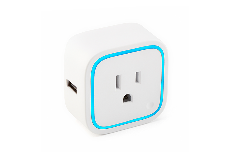
Aeotec by Aeon Labs Smart Switch 6.
Aeotec Smart Switch 6 is a low-cost Z-Wave Switch plug-in® module specifically used to enable Z-Wave command and control (on/off) of any plug-in tool. It can report immediate wattage consumption or kWh energy usage over a period of time. In the event of power failure, non-volatile memory retains all programmed information relating to the unit’s operating status.Its surface has a Smart RGB LED, which can be used for indicating the output load status or strength of the wireless signal. You can configure its indication colour according to your favour.The Smart Switch is also a security Z-wave device and supports the Over The Air (OTA) feature for the products firmware upgrade.
Familiarize yourself with your Smart Switch.

(Note: this figure is a sample of USA version. For other versions, the product appearance would be different).
Quick start.
Getting your Smart Switch up and running is as simple as plugging it into a wall socket and adding it to your Z-Wave network. The following instructions tell you how to add your Plug to your Z-Wave network via Aeotec by Aeon Labs’ Z-Stick or Minimote controller. If you are using other products as your main Z-Wave controller, such as a ZWave gateway, please refer to the part of their respective manual that tells you how to add new devices to your network.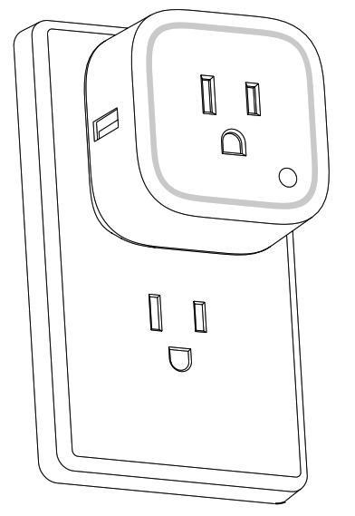
If you’re using a Z-Stick:
- Decide on where you want your Plug to be placed and plug it into a wall outlet.
- If your Z-Stick is plugged into a gateway or a computer, unplug it.
- Take your Z-Stick to your Plug.
- Press the Action Button on your Z-Stick.
- Press the Action Button on your Plug.
- If Plug has been successfully added to your Z-Wave network, its RGB LED will be solid. If the adding was unsuccessful, the red LED will be on for 2 seconds and then remain colourful gradient status, repeat the instructions from step 4. Press the Action Button on the Z-Stick to take it out of inclusion mode and then return it to your gateway or computer.
If you’re using a Minimote:

- Decide on where you want your Switch to be placed and plug it into a wall socket.
- Take your Minimote to your Plug.
- Press the Include button on your Minimote.
- Press the Action Button on your Plug.
- If Plug has been successfully added to your Z-Wave network, its RGB LED will be solid. If the adding was unsuccessful, the red LED will be on for 2 seconds and then remain colourful gradient status, repeat the instructions from step 4.
- Press any button on your Minimote to take it out of inclusion mode.
With your Smart Switch now working as a part of your smart home, you’ll be able to configure it from your home control software. Please refer to your software’s user guide for precise instructions on configuring Plug to your needs.The colour of RGB LED will change according to the output load power level when it is in Energy mode:
| Version | LED indication | Output (W) |
| US | Green | [0W, 900W) |
| Yellow | [900W, 1600W) | |
| Red | [1600W, 2000W) | |
| AU | Green | [0W, 1000W) |
| Yellow | [1000W, 2000W) | |
| Red | [2000W, 2500W) | |
| EU | Green | [0W, 1500W) |
| Yellow | [1500W, 2500W) | |
| Red | [2500W, 3000W) |
You can also configure the brightness of RGB LED when the Smart Switch is in Energy mode, Momentary Indicate mode, or Night Light mode.
Removing your Plug from a Z-Wave network.Your Smart Switch can be removed from your Z-Wave network at any time. You’ll need to use your Z-Wave network’s main controller to do this and the following instructions will tell you how to do this using Aeotec by Aeon Labs’ Z-Stick or Minimote controller. If you are using other products as your main Z-Wave controller, please refer to the part of their respective manuals that tells you how to remove devices from your network.If you’re using a Z-Stick:
- If your Z-Stick is plugged into a gateway or a computer, unplug it.
- Take your Z-Stick to your Plug.
- Press the Action Button on your Z-Stick.
- Press the Action Button on your Plug.
- If your Plug has been successfully removed from your network, its RGB LED will remain in colourful gradient status. If the removal was unsuccessful, the RGB LED will still be solid (Energy mode state when the output is on or Night light mode state when the output load is off), repeat the instructions from step 3.
- Press the Action Button on the Z-Stick to take it out of removal mode.
If you’re using a Minimote:
- Take your Minimote to your Smart Switch.
- Press the Remove Button on your Minimote.
- Press the Action Button on your Smart Switch.
- If your Plug has been successfully removed from your network, its RGB LED will remain the colourful gradient status. If the removal was unsuccessful, the RGB LED will still be solid (Energy mode state when the output is on or Night light mode state when the output load is off), repeat the instructions from step 2.
- Press any button on your Minimote to take it out of removal mode.
Advanced functions.
Changing LED mode.You can change the mode of how the LED acts by configuring the Smart Switch. There are 3 different modes: Energy mode, Momentary indicate mode and Night light mode.Energy mode will allow the LED to follow the state of the Smart Switch, when the switch is on, the LED will be on, and while the switch is off, the current colour LED will be off and then remain the purple colour of 10% brightness. Momentary indicate mode will momentarily turn the LED on for 5 seconds then turn off after every state change in the switch. Night light mode will allow the LED to be turned on and off during the selected time of day you have configured for it.Parameter 81 [1-byte dec] can be set to:(0) Energy Mode(1) Momentary Indicate Mode(2) Night Light Mode♦ Security or Non-security feature of your Smart Switch in Z-wave network.
Including Smart Switch as a non-secure device:If you want your Smart Switch to be a non-security device in your Z-wave network, you need to press the Action Button once on Plug when you use a controller/gateway to add/include your Plug. If the inclusion is successful, the green LED will be on for 2 seconds and then return to Energy mode state when the output load is on the state (the RGB LED remains solid) or Night light mode state when the output load is off state (the RGB LED remains solid with 10% brightness of purple colour). If the inclusion is unsuccessful, the red LED will be on for 2 seconds and then remain the colourful gradient status.
Including Smart Switch as a secure device:In order to take full advantage of all functionality of the Plug, you may want your Plug is a security device that uses secure/encrypted messages to communicate in your Z-wave network, so a security-enabled controller/ gateway is needed and then you need to press the Plug’s Action Button 2 times within 1 second when your security controller/gateway starts the network inclusion. If the inclusion is successful, the blue LED will be on for 2 seconds and then return to Energy mode state when the output load is on the state (the RGB LED remains solid) or Night light mode state when the output load is off state (the RGB LED remains solid with10% brightness of purple colour). If the inclusion is unsuccessful, the red LED will be on for 2 seconds and then remain the colourful gradient status.
Reset your Smart SwitchIf at some stage, your primary controller is missing or inoperable, you may wish to reset all of your Oomi Plug’s settings to their factory defaults. To do this, press and hold the Action Button for 20 seconds and then release it. Your Oomi Plug will now be reset to its original settings and the green LED will be solid for 2 seconds and then remain the colourful gradient status as a confirmation.
Technical specifications.
Model number: ZW096.Max standby power: 0.5W.USB output: DC 5V±0.3V, 1000mA.Operating temperature: 0°C to 40°C.Relative humidity: 8% to 80%.Z-Wave operating distance: Up to 100 feet/30 metres indoors or 300 feet/100 metres outdoors. AC input:
| Version | Input | Working band |
| AU | 230V 50Hz, Max: 10A | 921.42MHz |
| BR | 220V 60Hz, Max: 10A | 921.42MHz |
| CN | 220V 50Hz, Max: 10A | 68.42MHz |
| EU | 230V 50Hz, Max: 13A | 68.42MHz |
| IL | 230V 50Hz, Max: 10A | 68.42MHz |
| IN | 230V 50Hz, Max: 6A | 65.22MHz |
| UK | 230V 50Hz, Max: 13A | 68.42MHz |
| US | 120V 60Hz, Max: 15A | 908.42MHz |
Warranty.
If you are in need of any technical support during or subsequent to your product’s warranty, please get in touch with our support team via http://aeotec.com/support. The Company you bought this product from has also guaranteed to assist you with any of your support needs, and you can also contact them accordingly.This guarantee made by the company who you purchased the product includes the transfer of Aeon Labs’ full warranty to that Company. They’ve guaranteed that they’ll be able to assist you, the Customer, with all technical support and repair needs on our behalf.
Aeon Labs warrants to the original purchaser of Products, that is the Company who you have purchased from, that for the Warranty Period (as defined below), the Products will be free from material defects in materials and workmanship. The foregoing warranty is subject to the proper installation, operation and maintenance of the Products in accordance with installation instructions and the operating manual supplied. Warranty claims must be made to the Company you have purchased in writing within thirty (30) days of the manifestation of a problem.
Aeon Labs’ sole obligation under the foregoing warranty is, at Aeon Labs’ option, to repair, replace or correct any such defect that was present at the time of delivery, or to remove the Products and to refund the purchase price to Company. The Warranty Period begins on the date the product is delivered and continues for 12 months. Any repairs under this warranty must be conducted by an authorized Aeon Labs service representative and under Aeon Labs’ RMA policy. Any repairs conducted by unauthorized persons shall void this warranty.Excluded from the warranty are problems due to accidents, acts of God, civil or military authority, civil disturbance, war, strikes, fires, other catastrophes, misuse, misapplication, storage damage, negligence, electrical power problems, or modification to the Products or its components.
Aeon Labs does not authorize any person or party to assume or create for it any other obligation or liability in connection with the Products except as set forth herein. Aeon Labs will pass on to Company all manufacturers’ Material warranties to the extent that they are transferable, but will not independently warrant any Material. The company will assist the Customer with all warranty, repair, return and technical support needs, Company must prepay shipping and transportation charges for returned Products, and insure the shipment or accept the risk of loss or damage during such shipment and transportation. Aeon Labs will ship the repaired or replacement products to Company freight prepaid. Customer and Company shall indemnify, defend, and hold Aeon Labs and Aeon Labs’ affiliates, shareholders, directors, officers, employees, contractors, agents and other representatives harmless from all demands, claims, actions, causes of action, proceedings, suits, assessments, losses, damages, liabilities, settlements, judgments, fines, penalties, interest, costs and expenses (including fees and disbursements of counsel) of every kind (i) based upon personal injury or death or injury to property, to the extent, any of the foregoing is proximately caused either by a defective product (including strict liability in tort) or by the negligent or willful acts or omissions of Customer or its officers, employees, subcontractors or agents, and/or (ii) arising from or relating to any actual or alleged infringement or misappropriation of any patent, trademark, mask work, copyright, trade secret or any actual or alleged violation of any other intellectual property rights arising from or in connection with the products, except to the extent that such infringement exists as a result of Aeon Labs’ manufacturing processes.
IN NO EVENT SHALL AEON LABS BE LIABLE FOR ANY INDIRECT, INCIDENTAL, PUNITIVE, SPECIAL OR CONSEQUENTIAL DAMAGES, OR DAMAGES FOR LOSS OF PROFITS, REVENUE, OR USE INCURRED BY CUSTOMER, COMPANY OR ANY THIRD PARTY, WHETHER IN AN ACTION IN CONTRACT, OR TORT, OR OTHERWISE EVEN IF ADVISED OF THE POSSIBILITY OF SUCH DAMAGES. AEON LABS’ LIABILITY AND CUSTOMER’S EXCLUSIVE REMEDY FOR ANY CAUSE OF ACTION ARISING IN CONNECTION WITH THIS AGREEMENT OR THE SALE OR USE OF THE PRODUCTS, WHETHER BASED ON NEGLIGENCE, STRICT LIABILITY, BREACH OF WARRANTY, BREACH OF AGREEMENT, OR EQUITABLE PRINCIPLES, IS EXPRESSLY LIMITED TO, AT AEON LABS’ OPTION, REPLACEMENT OF, OR REPAYMENT OF THE PURCHASE PRICE FOR THAT PORTION OF PRODUCTS WITH RESPECT TO WHICH DAMAGES ARE CLAIMED. ALL CLAIMS OF ANY KIND ARISING IN CONNECTION WITH THIS AGREEMENT OR THE SALE OR USE OF PRODUCTS SHALL BE DEEMED WAIVED UNLESS MADE IN WRITING WITHIN THIRTY (30) DAYS FROM AEON LABS’ DELIVERY, OR THE DATE FIXED FOR DELIVERY IN THE EVENT OF NONDELIVERY. THE INDEMNITY AND WARRANTY IN ABOVE ARE EXCLUSIVE AND IN LIEU OF ALL OTHER INDEMNITIES OR WARRANTIES, WHETHER EXPRESS OR IMPLIED, INCLUDING THE IMPLIED WARRANTIES OF MERCHANTABILITY AND FITNESS FOR A PARTICULAR PURPOSE.
 FCC NOTICE (for USA)
THE MANUFACTURER IS NOT RESPONSIBLE FOR ANY RADIO OR TV INTERFERENCE CAUSED BY UNAUTHORIZEDMODIFICATIONS TO THIS EQUIPMENT. SUCH MODIFICATIONS COULD VOID THE USER’S AUTHORITY TO OPERATE THE EQUIPMENT.STORE INDOORS WHEN NOT IN USE. SUITABLE FOR DRY LOCATIONS. DO NOT IMMERSE IN WATER. NOT FOR USE WHERE DIRECTLY EXPOSED TO WATER.This device complies with Part 15 of the FCC Rules.Operation is subject to the following two conditions:1. This device may not cause harmful interference, and2. This device must accept any interference received, including interference that may cause undesired operation. This equipment has been tested and found to comply with the limits for a Class B digital device, pursuant to part 15 of the FCC Rules. These limits are designed to provide reasonable protection against harmful interference in a residential installation. This equipment generates, uses and can radiate radio frequency energy and, if not installed and used in accordance with the instructions, may cause harmful interference to radio communications. However, there is no guarantee that interference will not occur in a particular installation. If this equipment does cause harmful interference to radio or television reception, which can be determined by turning the equipment off and on, the user is encouraged to try to correct the interference by one or more of the following measures:
- Reorient or relocate the receiving antenna.
- Increase the separation between the equipment and receiver.
- Connect the equipment into an outlet on a circuit different from that to which the receiver is connected.
- Consult the dealer or an experienced radio/TV technician for help.
Warning
Do not dispose of electrical appliances as unsorted municipal waste, use separate collection facilities. Contact your local government for information regarding the collection systems available.
Certifications (regional):
 Z-Wave and Z-Wave Plus have registered trademarks of Sigma Designs and its subsidiaries in the United States and other countries
FCC ID: XBAFT096

Association information.
Smart Switch supports 2 association groups and can add max 5 nodes for each group.
| Association Group | Nodes | Send Mode |
Send commands |
| Group 1 | 0 | N/A | N/A |
| [1,5] | Single Cast | When the state of Smart Switch (turn on/off the load) is changed:1. Set Configuration parameter 80 to 0:Reserved (Default).2. Set Configuration parameter 80 to 1:Send Hail CC.3. Set Configuration parameter 80 to 2:Send the Basic Report. | |
| Group 2 | 0 | N/A | N/A |
| [1,5] | Single Cast | Forward the Basic Set, Switch Binary Set to associated nodes in Group 2 when the Smart Switch receives the Basic Set, Switch Binary Set commands from main controller. |
5.4 Association Group Info Command Class
- Association Group Info Report Command Class
Profile: General: NA (Profile MSB=0, Profile LSB=1)
5.4.2 Group 1: Lifeline
Group 2: Retransmit Association Group Name Report Command ClassGroup 1: LifelineGroup 2: Retransmit
Configuration parameters information.
| Parameter Number Hex / Decimal | Description | Default Value | Size |
| 0x03 (3) | Current Overload Protection. The load will be closed when the Current overrun (US: 16.5A, AU: 10.5A, EU: 14) and the time more than 2 minutes (0=disabled, 1=enabled). | 1 | 1 |
| 0x14 (20) | Configure the output load status after re-power on(0=last status, 1=always on, 2=always off) | 0 | 1 |
| 0x21 (33) | Set the RGB LED colour value for testing.Value1: ReservedValue2: Red valueValue3: Green valueValue4: Blue value | – | 4 |
| 0x50 (80) | Enable to send notifications to associated devices (Group 1) when the state of Micro Switch’s load changed (0=nothing, 1=hail CC, 2=basic CC report). | 0 | 1 |
| 0x51 (81) | Configure the state of the LED when it is in 3 modes below:0= The LED will follow the status (on/off) of its load (Energy mode).1= When the state of the Switch’s load changed, The LED will follow the status (on/off) of its load, but the red LED will turn off after 5 seconds if there is no switch action (momentary indicate mode).2= Night light mode. | 0 | 1 |
| Parameter Number Hex / Decimal | Description | Default Value | Size |
| 0x53 (83) | Configure the RGB value when it is in Night light mode.Value1: Red color valueValue2: Green color valueValue3: Blue color value | Value1=0x1BValue2=0x14Value3=0x1B | 3 |
| 0x54 (84) | Configure the brightness level of RGB LED (0%-100%) when it is in EnergyMode/momentary indicate mode.Value1: green colour value.Value2: yellow colour value.Value3: red colour value. | Green=0x32Yellow=0x32Red=0x32 | 3 |
| 0x5A (90) | Enables/disables parameter 91 and 92 below (1=enabled, 0=disabled). | 0 | 1 |
| 0x5B (91) | The value here represents a minimum change in wattage (in terms of wattage) for a REPORT to be sent (Valid values 0-60000). | 25 (W) | 2 |
| 0x5C (92) | The value here represents a minimum change in wattage per cent (in terms of percentage) for a REPORT to be sent (Valid values 0-100). | 5 (%) | 1 |
| 0x65 (101) | Which reports need to send in Report group 1 (See flags in the table below). | 0x00 00 00 00 | 4 |
| 0x66 (102) | Which reports need to send in Report group 2 (See flags in the table below). | 0x00 00 00 00 | 4 |
| 0x67 (103) | Which reports need to send in Report group 3 (See flags in the table below). | 0x00 00 00 00 | 4 |
| 0x6F (111) | The time interval of sending Report group 1 (Valid values 0x01- 0x7FFFFFFF). | 0x00 00 00 03 | 4 |
| 0x70 (112) | The time interval of sending Report group 2 (Valid values 0x01- 0x7FFFFFFF). | 0x00 00 02 58 | 4 |
| 0x71 (113) | The time interval of sending Report group 3 (Valid values 0x01- 0x7FFFFFFF). | 0x00 00 02 58 | 4 |
| Parameter Number Hex / Decimal | Description | Default Value | Size |
| 0xC8 (200) | Partner ID (0= Aeon Labs Standard Product, 1= others). | 0 | 1 |
| 0xFC (252) | Enable/disable Configuration Locked (0 =disable, 1 = enable). | 0 | 1 |
| 0xFE (254) | Device Tag | 0 | 2 |
| 0xFF (255) | Reset configuration set up to default setting. | N/A | 1 |
configuration Values for parameter 101-103:
| 7 | 6 | 5 | 4 | 3 | 2 | 1 | 0 | |
| configurationValue 1(MSB) | Reserved | |||||||
| configurationValue 2 | Reserved | |||||||
| configurationValue 3 | Reserved | |||||||
| configurationValue 4(LSB) | Reserved | Reserved | Reserved | Reserved | Auto send Meter REPORT (for kWh) at the group time interval | Auto send Meter REPORT (for watt) at the group time interval | Auto send Meter REPORT (for current) at the group time interval | Auto send Meter REPORT (for voltage at the group time interval |
References
[xyz-ips snippet=”download-snippet”]