AeoTec ZWA019 Water Sensor 7 Pro

Aeotec Water Sensor 7 has been crafted as a safety sensor to help detect and prevent floods and water leaks using Z-Wave Plus. It is powered by Aeotec’s Gen7 (https://aeotec.com/z-wave-home-automation/z-wave-gen7.html) technology and S2 framework. You can find out more about Water Sensor 7 (https://aeotec.com/z-wave-door-window-sensor) by following that link.
To see whether Water Sensor 7 is known to be compatible with your Z-Wave system or not, please reference our Z-Wave gateway comparison (http://aeotec.com/z-wave-gateways) listing. The technical specifications of Water Sensor 7(https://aeotec.freshdesk.com/a/solutions/articles/6000218908-door-window-sensor-7-technical-specifications-) can be viewed at that link.
Familiarize yourself with your Water Sensor 7.
Package contents:
1. Sensor Unit.2. Cover.3. Double-Sided Tape large (×2).4. Screws (×4).5. Dowels( x4).
Important safety information.
Please read this and other device guides carefully. Failure to follow the recommendations set forth by Aeotec Limited may be dangerous or cause a violation of the law. The manufacturer, importer, distributor, and/or reseller will not be held responsible for any loss or damage resulting from not following any instructions in this guide or in other materials.Keep product and batteries away from open flames and extreme heat. Avoid direct sunlight or heat exposure. Always remove all batteries from products that are being stored and not used. Batteries may damage the appliance if they leak. Do not use rechargeable batteries. Ensure correct polarity when inserting the batteries. Improper battery use may damage the product.Water Sensor 7 is intended for indoor use in dry locations only. Do not use in damp, moist, and/or wet locations.It contains small parts; keep away from children.
Installation of Water Sensor 7 Pro.
- Open the cover by pressing the clip on the side and pulling the cover upwards.
- Insert a fresh 1 * 1/2 AA battery, but pay attention to the polarity

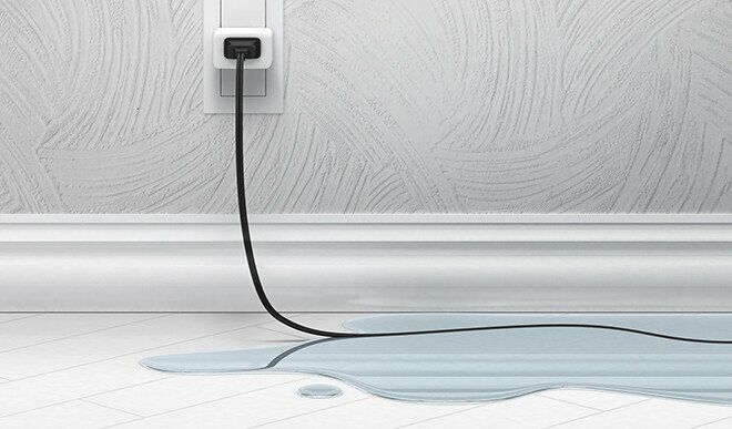
Install your Water Sensor 7 Pro.The Water Sensor 7 should be placed wherever you want to monitor for possible flooding or leaks. When placing the Water Sensor 7, consider the direction in which a flood or leak may flow and where it may occur. The contacts of the Water Sensor 7 probe will detect the liquid, so the probe must be placed so that any flood or leak will come into contact with it. When the probe contacts come into contact with a liquid, the Water Sensor 7 sends a leak warning to your Z-Wave Gateway. Make sure that both contacts are capable of detecting leaks or flooding.
Adding your Water Sensor 7 to Z-Wave network
SmartStart Inclusion.You can use this method of inclusion only if your Z-Wave gateway/controller/hub supports SmartStart.
1. Open up your Z-Wave gateway/controller/app.2. Select SmartStart inclusion.a3. Scan the QR code located on the Water Sensor 7.4. Within 10 minutes after powering your Water Sensor 7, it will automatically get included into your Z-Wave gateway/controller/hub.
Classic Inclusion
1. Set your Z-Wave controller into pairing mode.2. Triple-click the tamper switch on Water Sensor 7 – this begins to blink five times3. After completion of the inclusion, the LED will illuminate green for 3 seconds.4. If you pairing with S2 encryption/security, enter the first 5 digits of the DSK into your controller/gateway/hub interface when requested.5. Close the cover

Functions of Water Sensor 7 Pro.
Water leakOnce installed, this sensor will report wet or dry via Notification Command Class when this devices is wet or removed from water.
- Notification Report
- Type: Unknown (0x05)
- Value: Wet (0x02) or Dry (0x00)
TamperTamper alarm will be sent if the cover is removed.
- Notification Report
- Type: Tamper Removed (0x07)
- Value: 0x03
TemperatureThis sensor will report occasionally on its own as an unsolicited Multilevel Sensor Report either by a timed interval (Parameter 18) or by the change in value (Parameter 16).Multilevel Sensor Report
HumidityThis sensor will report occasionally on its own as an unsolicited Multilevel Sensor Report either by a timed interval (Parameter 18) or by the change in value (Parameter 17). Multilevel Sensor Report
LED indicator
| Function Description | LED Indicator |
| Device Not in Network | Blinks red for 5 seconds (1 sec duty cycle) when battery is inserted and sensor is not in network |
| Include/Exclude/Learn Mode | Illuminate green for 3 seconds when Inclusion / Exclusion / Configuration is successful.
Illuminate red for 3 seconds when Inclusion / Exclusion / Configuration is unsuccessful (upon a timeout of 30 seconds). |
| Local Reset | When device is locally reset to Factory Default LED blinks red (1 second duty cycle) for 5 seconds. |
| LowBatt | When operation button is Short Pressed the LED blinks red three time (1 sec duty cycle) |
| Tampering | If either Tamper Switch 1 or 2 is activated the device blinks red one time with ½ second duty cycle if within range of Controller.
The device blinks red three times with ½ second duty cycle if out of range of Controller |
| Water protection | When operation button is Short Pressed the LED illuminates red three seconds in case of Water Leakage detected and Green if no Leakage detected. |
| Push Type | Function | Description |
| Long Press 5s | Pending reset | LEDs start indication Waiting for Reset. |
| Long Press 10s | Reset | Initiates Device Reset Locally. |
| Short Press | Tamper | Sends Wake Up notification. |
| 3 Times Short Press | Sequence | See Learn Mode. |
Advanced Functions.
Communication test.
This utilizes the Power Level command class to determine the health between the Water Sensor 7 and your Z-Wave gateway. This will tell you if the Water Sensor 7 has a healthy connection to your system and is a great method of debugging connectivity issues.
1. Set Parameter #4 to value #12. Double click the Tamper Switch.3. Result:
- Green LED blinks once – success
- Red LED blinks 3x times – failure
Firmware-Update over the Air.
This device is capable of receiving a new firmware ‘over the air’. The update function needs to be supported by the central controller. Once the controller starts the update process, perform the following action to confirm the firmware update:
1. Wake Up the device by removing the cover.2. The hit the tamper switch once.
Send a wake up notification.
In order to send your sensors new configuration commands from your Z-Wave controller or gateway, it will need to be woken up.
1. Wake Up the device by removing the cover.2. The hit the tamper switch once.
Note: Water Sensor 7 remains awake until the housing is closed again.
Remove your Water Sensor 7 from Z-Wave network.
Your sensor can be removed from your Z-Wave network at any time. You’ll need to use your Z-Wave network’s main controller/gateway. To do this, please refer to the part of your gateways respective manual that tells you how to remove devices from your network.
1. Set your Z-Wave controller into unpair mode.2. Triple-click the tamper switch on Water Sensor 7 within 1.5 seconds – this will cause the LED to blink five times.3. After a successful exclusion, it will light up its LED for 2 seconds then deactivate.
Reset your Water Sensor 7.
This device also allows being reset without any involvement of a Z-Wave controller. This procedure should only be used when the primary controller is inoperable.To manually factory reset:
1. Remove the cover of Water Sensor 72. Press and hold tamper switch for 5 seconds until the red LED blinks.3. Release the tamper switch4. Immediately press and hold the tamper switch for 5 seconds until the red LED blinks.
Association Groups
Group Association allows Water Sensor to directly communicate with other Z-Wave devices directly without the need for the Z-Wave Controller to act as a inbetween controller. This using this function will help with communication effeciency and limit the amount of time it takes to control a device.
| Group Number | Maximum Nodes | Description |
| 1 | 5 | Lifeline |
| 2 | 5 | Control devices when water leakage is detected |
| 3 | 5 | Sends out alarm message when water leakage is detected |
| 4 | 5 | Sends alarm messages when tamper is tripped |
Parameter setting
Visual LED indicationsParameter: 3Size: 1 ByteDefault Value: 7Description: This parameter defines when the red LED will indicate events. Disabling all indications may extend battery life.(values 1 + 2 + 4 summarized)0 – No indications1 – Water Leakage Status Change2 – Wake Up (1 x click)4 – Device tampering
Range test after double clickParameter: 4Size: 1 ByteDefault Value: 0Description: Allows to enable the activation of a Z-Wave range test with double-clicking the tamper switch.0 – disabled1 – enabled
2nd Association Group TriggerParameter: 5Size: 1 ByteDefault Value: 0Description: This parameter defines the status of the water leakage that causes sending a BASIC command to all devices of Association Group 2.0 – Switch after Water Leakage Start and Stop1 – Switch after Water Leakage Start2 – Switch after Water Leakage Stop
Command Sent to Devices of Association Group 2Parameter: 6Size: 1 ByteDefault Value: 255Description: This parameter defines which commands is sent to 2nd Association Group0 – On1 – Off2 – On and Off
BASIC command value sent to 2nd Association Group on On eventParameter: 7Size: 1 ByteDefault Value: 255Description: This is the BASIC command value sent in case of On even0 – 99 – Value255 – On
BASIC command value sent to 2nd Association Group on Off eventParameter: 8Size: 1 ByteDefault Value: 0Description: This is the BASIC command value sent in case of Off event.0 – 99 – Value255 – On
Time Delay of On command frameParameter: 9Size: 2 ByteDefault Value: 0Description: On command is sent after a delay defined in this parameter. 0 – 32400 – Seconds
Time delay of Off command frameParameter: 10Size: 2 ByteDefault Value: 0Description:Off command is sent after a delay defined in this parameter.0 – 32400 – Seconds
Delay of tamper alarm cancellation.Parameter: 11Size: 2 ByteDefault Value: 0Description:Time a tamper alarm is delayed.0 – 32400 – Seconds
Reporting tamper alarm cancellationParameter: 12Size: 1 ByteDefault Value: 1Description: This parameter defines if the alarm cancellation event is reported.0 – do not send report1 – send report
Minimum Temperature change to report.Parameter: 16Size: 1 ByteDefault Value: 20Description:This value defines the minimum change of temperature to cause an unsolicited report of humidity to the central controller using Lifeline. If the value is set to 0, there will be no reports sent to the controller, when the temperature changes. However, periodic reports, managed by configuration parameter 18, may still be active.0 – disabled1-100 – 0,1 degree step
Minimum humidity change to report.Parameter: 17Size: 1 ByteDefault Value: 5Description:This value defines the minimum change of humidity to cause an unsolicited report of humidity to the central controller using Lifeline. If the value is set to 0, there will be no reports sent to the controller, when the humidity changes. However, periodicreports, managed by configuration parameter 18, may still be active.0 – disabled1-20 – value in %
Periodic Reports.Parameter: 18Size: 2 ByteDefault Value: 43200Description:This parameter defines the time interval to send an unsolicited report. If the value is set to 0, there will be no periodic reports sent to the controller. However, reports on temperature/humidity changes, managed by configuration parameters 16 and 17, may still be active.0 – disabled900-65535 – value in seconds
Temperature ScaleParameter: 64Size: 1 ByteDefault Value: 1Description:This parameter sets the temperature scale.1 – Celsius2 – Fahrenheit
 report this ad
255. Reset ParameterParameter: 255Size: 4 ByteDefault Value: 0Description: This parameter helps reset configuration parameters and the device to factory defaults1- Reset all Parameter settings to their default settings.1431655765 – (0x55555555) Completely factory reset sensor and send device reset locally notification
References
Support – Aeotec
s3.amazonaws.com/cdn.freshdesk.com/data/helpdesk/attachments/production/6093719007/original/WdQM6U7A2h6DDThMfBIY7HnD4NJZsTyUZA.png?1570780984
Loading…
Water Sensor 7 Pro user guide (ZWA019) : Aeotec Help Desk
Support – Aeotec
Smallest Z-Wave door / window sensor with dry contact relay • Aeotec Aeotec gen7 z-wave Z-Wave security 2 z-wave smart start z-wave door sensor z-wave window sensor open window sensor door safe sensor aeotec door window sensor 7 aeotec door window sensor 7
s3.amazonaws.com/cdn.freshdesk.com/data/helpdesk/attachments/production/6093719009/original/xSqwjLNn7xB8x0R5dJlTlF3SM0BYgqGlsQ.png?1570780985
[xyz-ips snippet=”download-snippet”]