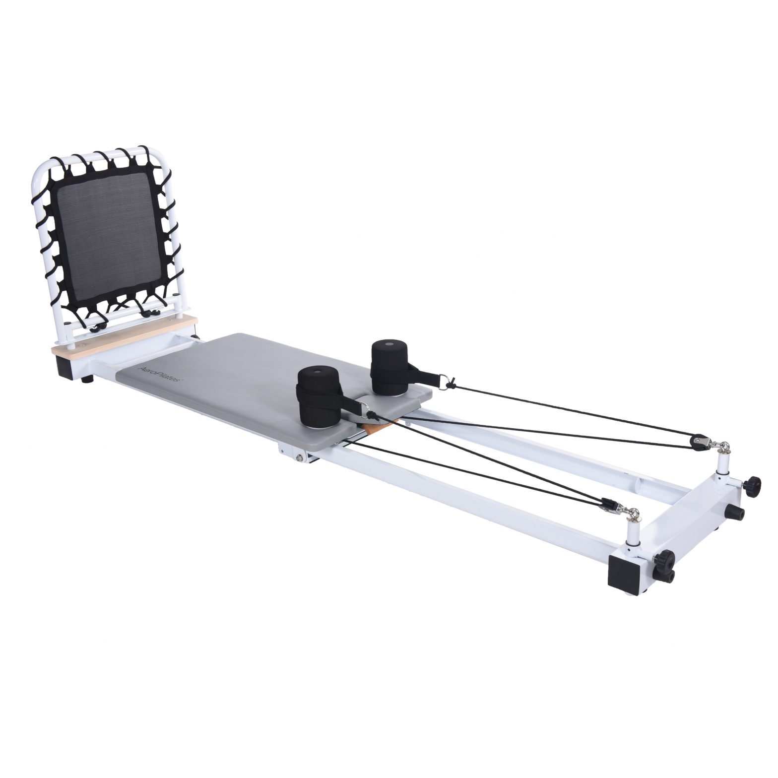
Aero Pilates Precision Series Reformer Owner’s Manual Product May Vary Slightly From Pictured.
WARNINGExercise can present a health risk. Consult a physician before beginning any exercise program with this equipment. If you feel faint or dizzy, immediately discontinue use of this equipment. Serious bodily injury can occur if this equipment is not assembled and used correctly. Serious bodily injury can also occur if all instructions are not followed. Keep others and pets away from equipment when in use. Always make sure all bolts and nuts are securely tightened prior to each use. Follow all safety instructions in this manual.
SAFETY INSTRUCTIONS
![]() Cancer and Reproductive Harm www.P65Warnings.ca.gov
Cancer and Reproductive Harm www.P65Warnings.ca.gov![]() Consult your physician before starting this or any exercise program. This is especially important if you are over the age of 35, have never exercised before, are pregnant, or suffer from any health problem. Failure to follow all warnings and instructions could result in serious injury or death.
Consult your physician before starting this or any exercise program. This is especially important if you are over the age of 35, have never exercised before, are pregnant, or suffer from any health problem. Failure to follow all warnings and instructions could result in serious injury or death.![]() The Bungee Cord(91) contain natural rubber latex which may cause allergic reactions.
The Bungee Cord(91) contain natural rubber latex which may cause allergic reactions.![]() To reduce the risk of serious injury, read the following Safety Instructions before using the AeroPilates® Precision Series Reformer 608.
To reduce the risk of serious injury, read the following Safety Instructions before using the AeroPilates® Precision Series Reformer 608.
- Save these instructions and ensure that other exercisers read this manual prior to using the AeroPilates® Precision Series Reformer 608 for the first time.
- Read all warnings and cautions posted on the AeroPilates® Precision Series Reformer 608.
- The AeroPilates® Precision Series Reformer 608 should only be used after a thorough review of the Owner’s Manual. Make sure that it is properly assembled and tightened before use.
- We recommend that two people be available for assembly of this product.
- When exercising on this product, do not exercise at an intensity that causes the product itself to move. This could result in damage to your joints and to the product.
- Keep children away from the AeroPilates® Precision Series Reformer 608. Do not allow children to use or play on the AeroPilates® Precision Series Reformer 608. Keep children and pets away from the AeroPilates® Precision Series Reformer 608 when it is in use.
- It is recommended that you place this exercise equipment on an equipment mat.
- Set up and operate the AeroPilates® Precision Series Reformer 608 on a solid level surface. Do not position the AeroPilates® Precision Series Reformer 608 on loose rugs or uneven surfaces.
- Make sure that adequate space is available for access to and around the AeroPilates® Precision Series Reformer 608.
- Before using, inspect the AeroPilates® Precision Series Reformer 608 for worn or loose components, and tighten or replace any worn or loose components prior to use.
- When folding or unfolding the AeroPilates® Precision Series Reformer 608, keep all children away from the AeroPilates® Precision Series Reformer 608 and make sure your hands are clear of any folding or pinch point.
- Consult a physician prior to commencing an exercise program and follow his/her recommendations in developing your fitness program. If at any time during exercise you feel faint, dizzy, or experience pain, stop and consult your physician.
- Always choose the workout which best fits your physical strength and flexibility level. Know your limits and train within them. Always use common sense when exercising.
- Do not wear loose or dangling clothing while using the AeroPilates® Precision Series Reformer 608.
- Be careful to maintain your balance while using, mounting, dismounting, or assembling the AeroPilates® Precision Series Reformer 608. Loss of balance may result in a fall and bodily injury.
- The AeroPilates® Precision Series Reformer 608 should not be used by persons weighing over 350 pounds.
- The AeroPilates® Precision Series Reformer 608 should be used by only one person at a time.
Costumer Care: register.staminaproducts.com
BEFORE YOU BEGIN
Thank you for choosing the AeroPilates® Precision Series Reformer 608. We take great pride in this quality product and hope it will provide many hours of quality exercise to make you feel better, look better, and enjoy life to its fullest.It’s a proven fact that a regular exercise program can improve your physical and mental health. Too often, our busy lifestyles limit our time and opportunity to exercise. The AeroPilates® Precision Series Reformer 608 provides a convenient and simple method to begin your journey of getting your body in shape and achieving a happier and healthier lifestyle.
Before reading further, please review the drawing below and familiarize yourself with the parts that are labeled. Locate the serial decal on the product and write the serial number on the cover of the manual in the space provided. See an image of the serial decal. Model number and serial number are required when calling for assistance.Read this manual carefully before using the AeroPilates® Precision Series Reformer 608.
Providing you with a quality product is Stamina’s top priority. However, sometimes there could be a missing or incorrectly sized part. If you have any questions or problems with the parts included with your AeroPilates® Precision Series Reformer 608, please do not return the product. Contact us FIRST!
If a part is missing or defective, please contact Customer Care for assistance. Call us toll free at 1-800-375-7520 (in the U.S.) or live chat on staminaproducts.com. Our Customer Care Staff is available to assist you from 7:30 A.M. to 5:00 P.M. (Central Time) Monday through Thursday and 8:00 A.M. to 3:00 P.M. (Central Time) on Friday.Be sure to have the name and model number of the product available when you contact us.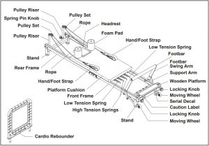
THE FOLLOWING TOOLS ARE INCLUDED FOR ASSEMBLY:
Allen Wrench (4mm): ![]() Allen Wrench (6mm):
Allen Wrench (6mm): ![]() Combination Wrench:
Combination Wrench: ![]()
EQUIPMENT WARNING, CAUTION & NOTICE LABELS
This chart is provided to help identify the warning, caution, and notice labels on the AeroPilates® Precision Series Reformer 608. Please take a moment to familiarize yourself with all of the warning, caution, and notice labels.
CAUTION LABEL(50)
SERIAL DECAL(51) To best serve you, our Customer Care Representatives willneed your serial number. For quick access, write in yourserial number on the cover of the manual.
HARDWARE IDENTIFICATION CHART
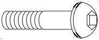
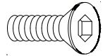
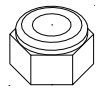
This chart is provided to help identify the hardware used in the assembly process. Place the washers or the ends of the bolts or screws on the circles to check for the correct diameter. Use the small scale to check the length of the bolts and screws.
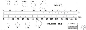
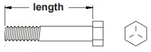 NOTICE: The length of all bolts and screws, except those with flat heads, is measured from below the head to the end of the bolt or screw. Flat head bolts and screws are measured from the top of the head to the end of the bolt or screw.
After unpacking the unit, open the hardware bag and make sure that you have all the following items. Some hardware may be already attached to the part.
|
Part Number and Description |
Qty |
|
|
|
0 Bolt, Button Head (M6 x 1 x 10mm) 62 Bolt, Button Head (M8 x 1.25 x 12mm) 63 Bolt, Button Head (M8 x 1.25 x 15mm) 64 Bolt, Button Head (M8 x 1.25 x 20mm) |
4 4 2 2 |
 |
0 Bolt, Button Head (M6 x 1 x 10mm) 4 62 Bolt, Button Head (M8 x 1.25 x 12mm) 4 63 Bolt, Button Head (M8 x 1.25 x 15mm) 2 64 Bolt, Button Head (M8 x 1.25 x 20mm) |
2 |
 |
0 Bolt, Flat Socket Head (M6 x 1 x 20mm) |
4 |
 |
77 Nylock Nut (M8 x 1.25) |
2 |
 |
83 Washer (M6)
84 Washer (M8) |
4 12 |
ASSEMBLY INSTRUCTIONS
Place all parts from the box in a cleared area and position them on the floor in front of you. Remove all packing materials from your area and place them back into the box. Do not dispose of the packing materials until assembly is completed. Read each step carefully before beginning. If you are missing a part, please go to staminaproducts.com under the Customer Care section and order the part needed, e-mail us at [email protected], or call us toll free at 1-800-375-7520 (in the U.S.). Our Customer Care Staff is available to assist you from 7:30 A.M. to 5:00 P.M. (Central Time) Monday through Thursday and 8:00 A.M. to 3:00 P.M. (Central Time) on Friday.
Some product parts are fit tested at the factory to ensure proper fit and alignment. Marks in the paint may be noticeable, but are not an indication of damage.
NOTE: We recommend that two people be available for assembly of this product.
STEP 1To connect the RAILS: Insert the REAR FRAME(2) into the CROSSING BAR(9) on the FRONT FRAME(1) and secure with BUTTON HEAD BOLTS(M6x1x10mm)(60) and WASHERS(M6)(83) from both sides, and BUTTON HEAD BOLTS(M8x1.25x12mm)(62) and WASHERS(M8)(84) from bottom.
STEP 2Screw the STANDS(10) into the FRONT FRAME(1) and REAR FRAME(2).
 STEP 3Attach the MOVING WHEELS(8) to the FRONT FRAME(1) with BUTTON HEAD BOLTS(M8x1.25x45mm) (68), WASHERS(M8)(84), and NYLOCK NUTS(M8x1.25)(77). Store the LOCKING KNOBS(6) by screwing them into the FRONT FRAME(1).
STEP 4The SUPPORT BAR(13) is packed and tied on the cradle in the FRONT FRAME(1). Untie the SUPPORT BAR(13) and remove the packing material. Insert the SUPPORT BAR(13) back into the cradle. Press a FOOTBAR BUSHING(17) into the RIGHT FOOTBAR SWING ARM(15R) and the LEFT FOOTBAR SWING ARM(15L). Attach the RIGHT FOOTBAR SWING ARM(15R) and the LEFT FOOTBAR SWING ARM(15L) to shafts in the FRONT FRAME(1) with BUTTON HEAD BOLTS(M8x1.25x15mm (63) and WASHERS(M8)(84). Attach the FOOTBAR(14) to the RIGHT FOOTBAR SWING ARM(15R) and the LEFT FOOTBAR SWING ARM(15L) with FLATHEAD SOCKET BOLTS(M6x1x20mm)(70). Attach the SUPPORT ARMS(16) to both ends of the SUPPORT BAR(13) with BUTTON HEAD BOLTS(M8x1.25x20mm)(64) and WASHERS(M8)(84).

STEP 5Insert the PULLEY RISERS(22) into the mounting holes in the REAR FRAME(2). Align one of the adjustment holes in the PULLEY RISERS(22) with the holes in the REAR FRAME(2) and secure with the SPRING PIN KNOBS(32).
STEP 6Insert the FOAM PAD ASSEMBLIES(53) into the holes located on the PLATFORM CUSHION(38). Place the HAND/FOOT STRAPS(34) onto the FOAM PAD ASSEMBLIES(53) for storage.

OPERATIONAL INSTRUCTIONS
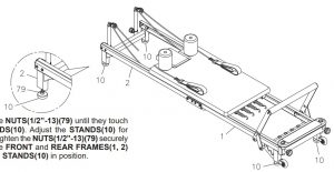
LEVELING THE AeroPilates® Precision Series Reformer 608
Adjust the STANDS(10) under the FRONT FRAME(1) and REAR FRAME(2) so that the AeroPilates® Precision Series Reformer 608 sits on the floor without rocking. Refer to the instructions below the illustration.
FOOTBAR ADJUSTMENT
The FOOTBAR(14) can be positioned at three angles. To adjust, lift the FOOTBAR(14) and swing the SUPPORT BAR(13) into desired slot in the cradle as shown in the illustration.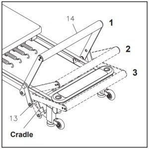
USING THE CARDIO REBOUNDER
Adjust the FOOTBAR(14) to the lowest position. Make sure that the holes in the CARDIO REBOUNDER(89) are facing toward the end of the AeroPilates® Precision Series Reformer 608 as shown in the illustration. Insert the CARDIO REBOUNDER(89) into the mounting holes located in the WOODEN PLATFORM(4) and FRONT FRAME(1). Insert the CARDIO REBOUNDER(89) all the way to the bottom and lock it in place with the LOCKING KNOBS(6).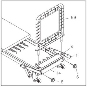
LOAD ADJUSTMENT
The AeroPilates® Precision Series Reformer 608 has four springs: two HIGH TENSION SPRINGS(48) identified with yellow bands and two LOW TENSION SPRINGS(49) identified with blue bands. The resistance of the PLATFORM(37) can be adjusted by attaching the springs to the EYEHOOKS(21). Springs are easily changed between exercises for an uninterrupted workout. The workout wall chart recommends how many and which springs to use for each exercise.
HEADREST ADJUSTMENT
The HEADREST(39) on the PLATFORM(37) can be positioned at three different angles, 0°, 14°, and 20°. Simply pivot the ANGLE ADJUSTER(40) underneath the HEADREST(39).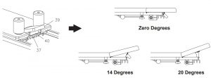
ROPE LENGTH ADJUSTMENT
The ROPE(36) feeds through the PULLEY SET(30), Loop A and Loop B, then the ball end is attached on the hook on the underside of the top edge of the PLATFORM(37).You can adjust the length between the PULLEY SET(30) and the HAND/FOOT STRAP(34).Pull the ROPE(36) from the gap between Loop A and Loop B and hang the ROPE(36) onto one of the three hooks.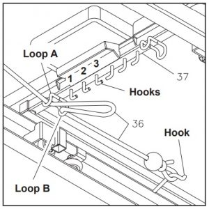
If more length is needed, unhook the ball end of the ROPE(36) from the hook. The ball will stop at Loop B, making this rope 8 inches longer. You can still pull the ROPE(36) from the gap between Loop A and Loop B and hang the ROPE(36) onto one of the three hooks to adjust the length.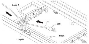
CUSTOMIZING ROPE LENGTH
Ideal rope length will vary depending on your height and limb length. To determine your ideal rope length, begin by placing the hand/foot straps over the shoulder rests as shown below. Adjust the ropes so they are taut. For complete rope length adjustment instructions, see additional Rope Length Adjustment instructions in this Owner’s Manual.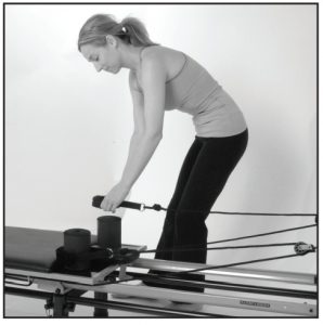
Next, lie on the reformer with your hands in the straps with shoulders against the shoulder rests. Reach your hands toward the ceiling until they are directly over the back edge of the reformer platform as shown below. In this position, the reformer platform should be at rest with no tension on the ropes. If there is still tension on the ropes in this position, lengthen the ropes. If you lose tension before reaching the arm position shown below, shorten the ropes.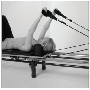
PULLEY HEIGHT ADJUSTMENT
Standard Setting- the top settingThe standard height setting for the reformer pulleys is the top setting. At the top setting, the pull of the ropes provides the most support and feedback for the body. Place your pulleys at the top setting to most easily achieve proper form and to engage the core muscles.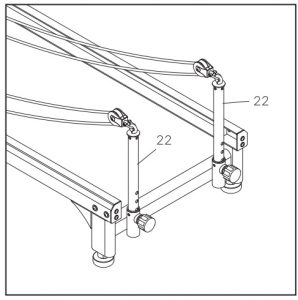
Variable settings- lower settingsYou can add variety to your routine by using different pulley settings. The lower you set the pulleys, the less guidance and support you receive from the ropes. By providing less guidance and support, the lower settings further challenge strength and coordination.There are four adjustment holes in the PULLEY RISERS(22). Remove the SPRING PIN KNOBS(32). Adjust the PULLEY RISERS(22) up or down and lock in desired position with the SPRING PIN KNOBS(32).
STORAGE
- To store the AeroPilates® Precision Series Reformer 608, simply keep it in a clean dry place.
- It is recommended that two people be available to move the AeroPilates® Precision Series Reformer 608.
- To move the AeroPilates® Precision Series Reformer 608: First, attach one of the TENSION SPRINGS(48, 49) to the EYEHOOK(21) to prevent the PLATFORM(37) from moving. Second, grasp the back end of the REAR FRAME(2) and lift the unit. Third, roll the AeroPilates® Precision Series Reformer 608 on the MOVING WHEELS(8) that are attached to the FRONT FRAME(1).
MAINTENANCE
The safety and integrity designed into the AeroPilates® Precision Series Reformer 608 can only be maintained when the AeroPilates® Precision Series Reformer 608 is regularly examined for damage and wear. Special attention should be given to the following:
- It is the sole responsibility of the user/owner to ensure that regular maintenance is reformed.
- Worn or damaged components must be replaced immediately or the AeroPilates® Precision Series Reformer 608 removed from service until repair is made.
- Verify that the CAUTION LABEL(50) is present and legible. Replace the CAUTION LABEL(50) if it is missing or damaged.
- Verify that the ROPES(36) are properly installed on the PULLEY SETS(30).
- Check the condition of the ROPES(36) and replace if they are frayed or worn.
- Check the condition of the TENSION SPRINGS(48, 49). Replace the springs that are damaged.
- Check the BUNGEE CORD(91) on the CARDIO REBOUNDER(89) for wear. Replace the CARDIO REBOUNDER(89) if the BUNGEE CORD(91) is frayed or worn.
- Check the PLASTIC SNAP HOOKS(92) on the ends of the BUNGEE CORD(91). Replace the CARDIO REBOUNDER(89) if PLASTIC SNAP HOOKS(92) are damaged or deformed.
- Check the PULLEY SETS(30) for excessive wear. Replace worn PULLEY SETS(30).
- Check the HAND/FOOT STRAPS(34) for damage. Replace damaged parts.
- Check the FOAM SLEEVE(55) and FOAM PADS(53). Replace if damaged or worn.
- Check the BUMPERS(12) for looseness or damage and replace any damaged parts.
- Check the PLATFORM CUSHION(38) and replace if it is damaged or worn.
- Check and clean the ROLLERS(42) and the rolling surfaces on the rails. Clean by wiping with a dry cloth.
- Only Stamina Products supplied components should be used to maintain/repair the AeroPilates® Precision Series Reformer 608.
- Keep your AeroPilates® Precision Series Reformer 608 clean by wiping with an absorbent cloth after use.
CONDITIONING GUIDELINES
How you begin your exercise program depends on your physical condition. If you have been inactive for several years or are severely overweight, start slowly and increase your workout time gradually. Increase your workout intensity gradually by monitoring your heart rate while you exercise.
Remember to follow these essentials:
- Have your doctor review your training and diet programs.
- Begin your training program slowly with realistic goals that have been set by you and your physician.
- Warm up before you exercise and cool down after you work out.
- Take your pulse periodically during your workout and strive to stay within a range of 60% (lower intensity) to 90% (higher intensity) of your maximum heart rate zone. Start at the lower intensity, and build up to higher intensity as you become more aerobically fit.
- If you feel dizzy or lightheaded you should slow down or stop exercising.
Initially you may only be able to exercise within your target zone for a few minutes; however, your aerobic capacity will improve over the next six to eight weeks. It is important to pace yourself while you exercise so you don’t tire too quickly.
To determine if you are working out at the correct intensity, use a heart rate monitor or use the table below. For effective aerobic exercise, your heart rate should be maintained at a level between 60% and 90% of your maximum heart rate. If just starting an exercise program, work out at the low end of your target heart rate zone. As your aerobic capacity improves, gradually increase the intensity of your workout by increasing your heart rate.
Measure your heart rate periodically during your workout by stopping the exercise but continuing to move your legs or walk around. Place two or three fingers on your wrist and take a six second heartbeat count. Multiply the results by ten to find your heart rate. For example, if your six second heartbeat count is 14, your heart rate is 140 beats per minute. A six second count is used because your heart rate will drop rapidly when you stop exercising. Adjust the intensity of your exercise until your heart rate is at the proper level.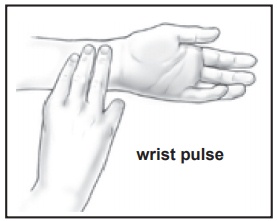
Target Heart Rate Zone Estimated by Age*
|
Age |
Target Heart Rate Zone(55%-90% of Maximum Heart Rate) |
Average MaximumHeart Rate 100% |
|
20 years |
110-180 beats per minute |
200 beats per minute |
|
25 years |
107-175 beats per minute |
195 beats per minute |
|
30 years |
105-171 beats per minute |
190 beats per minute |
|
35 years |
102-166 beats per minute |
185 beats per minute |
|
40 years |
99-162 beats per minute |
180 beats per minute |
|
45 years |
97-157 beats per minute |
175 beats per minute |
|
50 years |
94-153 beats per minute |
170 beats per minute |
|
55 years |
91-148 beats per minute |
165 beats per minute |
|
60 years |
88-144 beats per minute |
160 beats per minute |
|
65 years |
85-139 beats per minute |
155 beats per minute |
|
70 years |
83-135 beats per minute |
150 beats per minute |
* For cardiorespiratory training benefits, the American College of Sports Medicine recommends working out within a heart rate range of 55% to 90% of maximum heart rate. To predict the maximum heart rate, the following formula was used: 220 – Age = predicted maximum heart rate
WARM-UP and COOL-DOWN
Warm-UpThe purpose of warming up is to prepare your body for exercise and to minimize injuries.Warm up for two to five minutes before strength training or aerobic exercising. Perform activities that raise your heart rate and warm the working muscles. Activities may include brisk walking, jogging, jumping jacks, jump rope, and running in place.
StretchingStretching while your muscles are warm after a proper warm-up and again after your strength or aerobic training session is very important. Muscles stretch more easily at these times because of their elevated temperature, which greatly reduces the risk of injury.Stretches should be held for 15 to 30 seconds. Do not bounce.
Suggested Stretching Exercises
Lower Body Stretch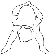 Place feet shoulder-width apart and lean forward.Keep this position for 30 seconds using the body as a natural weight to stretch the backs of the legs.DO NOT BOUNCE! When the pull on the back of the legs lessens, gradually try a lower position.
Bent Torso Pulls
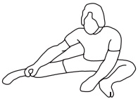 While sitting on the floor, have legs apart, one leg straight and one knee bent.Pull the chest down to touch the thigh on the leg that is bent, and twist at the waist.Hold this position at least 10 seconds. Repeat 10 times on each side.
Floor Stretch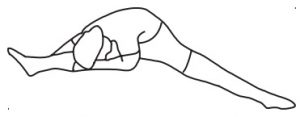
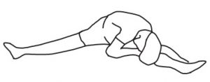 While sitting on the floor, open the legs as wide as possible. Stretch the upper body toward the knee on the right leg by using your arms to pull your chest to your thighs. Hold this stretch 10 to 30 seconds.DO NOT BOUNCE! Do this stretch 10 times.Repeat the stretch with the left leg.
Bent Over Leg Stretch Stand with feet shoulderwidth apart and lean forward as illustrated. Using the arms, gently pull the upper body towards the right leg.Let the head hang down.DO NOT BOUNCE!Hold the position a minimum of 10 seconds. Repeat pulling the upper body to the left leg. Do this stretch several times slowly
Remember to always check with your physician before starting any exercise program.
Cool-Down The purpose of cooling down is to return the body to its normal, or near normal, resting state at the end of each exercise session. A proper cool-down slowly lowers your heart rate and allows blood to return to the heart. Your cool-down should include the stretches listed above and should be completed after each strength training session.
LIMITED WARRANTY
WARRANTY
Stamina Products, Inc. (“Stamina”) warrants to the original purchaser that this product will be free from defects in materials and workmanship that arise under normal use, service, proper assembly and proper operation in accordance with product warnings/instructions for a period of 90 days on the parts and five years on the frame from the date of the original purchase from an authorized retailer. THISWARRANTY SHALL NOT APPLY TO ANY PRODUCT WHICH HAS BEEN SUBJECT TO ABUSE, MISUSE, ALTERATION OF ANY KIND OR TO ANY DEFECT OR CHANGE CAUSED BY IMPROPER ASSEMBLY, REPAIR, REPLACEMENT, SUBSTITUTION OR USE WITH PARTS NOT PROVIDED BY STAMINA.
To implement this limited warranty, send a written notice stating your name, date, and place of purchase and a brief description of the defect along with your receipt to Stamina Products, Inc. 2040 N AllianceAve, Springfield, Missouri, USA, MO 65803, or email us at [email protected], or call us at 1-800-375-7520. If the defect is covered under this limited warranty, you will be requested to return the product or part to us for free repair or replacement at our option.
NO ACTION FOR BREACH OF THIS LIMITED WARRANTY MAY BE COMMENCED MORE THAN ONE (1) YEAR AFTER THE DATE THE ALLEGED BREACH WAS OR SHOULD HAVE BEEN DISCOVERED. NO ACTION FOR BREACH OF ANY IMPLIED WARRANTY (INCLUDING MERCHANTABILITY AND FITNESS FOR A PARTICULAR PURPOSE) MAY BE COMMENCED MORE THAN ONE (1) YEAR AFTER DELIVERY OF THE PRODUCT TO THE PURCHASER. These warranties are not transferable. IF ANY PART OF THE PRODUCT IS NOT IN COMPLIANCE WITH THIS LIMITED WARRANTY OR ANY IMPLIED WARRANTY, THE REMEDY OF REPAIR OR REPLACEMENT IS THE EXCLUSIVE REMEDY. If any claim is made under this limited warranty or any implied warranty, Stamina reserves the right to require the product to be returned for inspection, at the purchaser’s expense, to Stamina’s premises in Springfield, Missouri. Return of the enclosed warranty registration card is not required for warranty coverage, but is merely a way of establishing the date and place of purchase.
Stamina SHALL NOT BE LIABLE FOR THE LOSS OF USE OF ANY PRODUCT, LOSS OF TIME, INCONVENIENCE, COMMERCIAL LOSS OR ANY OTHER INDIRECT, CONSEQUENTIAL, SPECIAL OR INCIDENTAL DAMAGES DUE TO BREACH OF THE ABOVE WARRANTY OR ANY IMPLIED WARRANTY.
THIS LIMITED WARRANTY IS THE ONLY EXPRESS WARRANTY. NO ORAL OR WRITTEN INFORMATION GIVEN BY STAMINA, ITS AGENTS OR EMPLOYEES, SHALL CREATE A WARRANTY OR IN ANY WAY INCREASE THE SCOPE OF THIS WARRANTY. This warranty gives you specific legal rights, and you may also have other legal rights which vary from state to state. ANY OTHER RIGHT WHICH YOU MAY HAVE, INCLUDING ANY IMPLIED WARRANTY OF MERCHANTABILITY OR FITNESS FOR A PARTICULAR PURPOSE, IS LIMITED IN DURATION TO THE DURATION OF THIS WARRANTY.
The laws in some states affect the disclaimer or limitation of implied warranties and consequential and incidental damages. If any such law is found applicable, the foregoing disclaimers and limitations of and on implied warranties and consequential and incidental damages shall be deemed to be modified to the extent necessary to comply with applicable law.
PRODUCT PARTS DRAWING
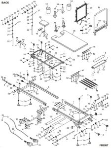
PARTS LIST
|
PART# |
PART NAME |
QTY |
|
1 |
Front Frame |
1 |
|
2 |
Rear Frame |
1 |
|
3 |
End Plate |
2 |
|
4 |
Wooden Platform |
1 |
|
5 |
Non-skid Pad |
1 |
|
6 |
Locking Knob | 2 |
|
7 |
Bushing |
6 |
|
8 |
Moving Wheel |
2 |
|
9 |
Crossing Bar |
1 |
|
10 |
Stand |
4 |
|
11 |
Stopper Bracket |
2 |
|
12 |
Bumper |
4 |
|
13 |
Support Bar |
1 |
|
14 |
Footbar |
1 |
|
15 |
Footbar Swing Arm |
2 |
|
16 |
Support Arm | 2 |
|
17 |
Footbar Bushing (Ø13.5 x Ø25 x 9mm) |
2 |
|
18 |
Spacer (Ø10.2 x Ø13 x 9mm) |
2 |
|
19 |
Nylon Washer (Ø13.2 x Ø25.4 x 2mm thick) |
2 |
|
20 |
Nut Cap (M10) |
2 |
| 21 |
Eyehook |
4 |
|
22 |
Pulley Riser |
2 |
|
23 |
Pulley Riser Eyehook | 2 |
|
24 |
Large Washer (Ø8.7 x Ø32 x 2mm) |
2 |
|
25 |
Pulley Bracket |
2 |
|
26 |
U-shaped Connector | 2 |
|
27 |
Connector Bolt (M5 x 0.8 x 22.2mm) |
2 |
|
28 |
Connector Shaft |
2 |
|
29 |
Pulley Spacer |
2 |
|
30 |
Pulley |
2 |
|
31 |
Pulley Bracket Cover |
4 |
|
32 |
Spring Pin Knob |
2 |
|
33 |
Oval Plug (40 x 80mm) |
2 |
|
34 |
Hand/Foot Strap |
2 |
| 35 |
Ball |
2 |
|
36 |
Rope |
2 |
|
37 |
Platform |
1 |
|
38 |
Platform Cushion |
1 |
|
39 |
Headrest |
1 |
|
40 |
Angle Adjuster |
1 |
|
41 |
Hinge |
2 |
|
42 |
Roller |
8 |
|
43 |
Roller Spacer (Ø8.5 x Ø12.7 x 5mm) |
4 |
|
44 |
Square Plug (20 x 20mm) |
4 |
|
45 |
Foam Pad Support Plate |
2 |
|
46 |
Rear Spring Strap |
1 |
|
47 |
Front Spring Strap |
1 |
|
48 |
High Tension Spring, Yellow Marked |
2 |
|
49 |
Low Tension Spring, Blue Marked |
2 |
|
50 |
Caution Label |
1 |
|
51 |
Serial Decal |
1 |
|
52 |
Foam Pad Tube |
2 |
|
53 |
Foam Pad |
2 |
|
54 |
Round Plug (Ø25.4mm, for tube 1.5mm thick) |
2 |
|
55 |
Foam Sleeve |
1 |
|
56 |
Allen Wrench (6mm) |
1 |
|
57 |
Allen Wrench (4mm) |
1 |
|
58 |
Bolt, Button Head (M4 x 0.7 x 12mm) |
2 |
|
59 |
Bolt, Button Head (M5 x 0.8 x 10mm, with threadlocker) |
4 |
|
60 |
Bolt, Button Head (M6 x 1 x 10mm) |
20 |
|
61 |
Bolt, Button Head (M6 x 1 x 15mm, with threadlocker) |
2 |
|
62 |
Bolt, Button Head (M8 x 1.25 x 12mm, with threadlocker) |
8 |
|
63 |
Bolt, Button Head (M8 x 1.25 x 15mm, with threadlocker) |
2 |
|
64 |
Bolt, Button Head (M8 x 1.25 x 20mm, with threadlocker) |
2 |
|
65 |
Bolt, Button Head (M8 x 1.25 x 25mm, with threadlocker) |
4 |
|
66 |
Bolt, Button Head (M8 x 1.25 x 35mm, with threadlocker) |
6 |
|
67 |
Bolt, Button Head (M10 x 1.5 x 25mm) |
2 |
|
68 |
Bolt, Button Head (M8 x 1.25 x 45mm) |
2 |
| 69 | Bolt, Button Head (M8 x 1.25 x 55mm) |
4 |
|
70 |
Bolt, Flat socket Head (M6 x 1 x 20mm, with threadlocker) |
4 |
|
71 |
Screw, Round Head (M4 x 15mm) |
11 |
|
72 |
Screw, Round Washer Head (M4 x 15mm) |
5 |
|
73 |
Screw, Flat Head (M5 x 15mm) |
6 |
|
74 |
Screw, Flat Head (M4 x 15mm) |
8 |
|
75 |
Nylock Nut (M4 x 0.7) |
2 |
| 76 |
Nylock Nut (M6 x 1) |
4 |
|
77 |
Nylock Nut (M8 x 1.25) |
10 |
|
78 |
Nylock Nut (M10 x 1.5) |
2 |
| 79 | Nut (1/2”-13) |
4 |
|
80 |
Lock Washer (M4) |
2 |
|
81 |
Arc Washer (M6) |
4 |
|
82 |
Washer (M5) |
14 |
|
83 |
Washer (M6) |
14 |
|
84 |
Washer (M8) |
26 |
|
85 |
Washer (M10) |
2 |
|
86 |
Screw, Flat Head (M5 x 0.8 x 22mm) |
2 |
|
87 |
Nylock Nut (M5 x 0.8) |
2 |
|
88 |
Combination Wrench |
1 |
|
89 |
Cardio Rebounder | 1 |
|
90 |
Cardio Rebounder Mat |
1 |
|
91 |
Bungee Cord |
1 |
|
92 |
Plastic Snap Hook |
2 |
|
93 |
Round Plug (Ø25.4mm, for tube 2mm thick) |
2 |
|
94 |
Manual |
1 |
|
95 |
Workout Chart |
1 |
TO CONTACT CUSTOMER CARE
For your convenience, Stamina’s customer care representatives can be reached by email at [email protected] or by phone at 1-800-375-7520 (in the U.S.). Our customer care representatives are available Monday through Thursday from 7:30 a.m. until 5:00 p.m., and Friday 8:00 a.m. until 3 p.m. Central Time.
References
Customer Care – Exercise Equipment | Stamina Products
Quality Home Fitness & Exercise Equipment | Stamina Products
P65Warnings.ca.gov
Customer Care – Exercise Equipment | Stamina Products
Customer Care – Exercise Equipment | Stamina Products
Quality Home Fitness & Exercise Equipment | Stamina Products
[xyz-ips snippet=”download-snippet”]