Aideepen Spot Welder Control Module SWM-103 Instruction Manual
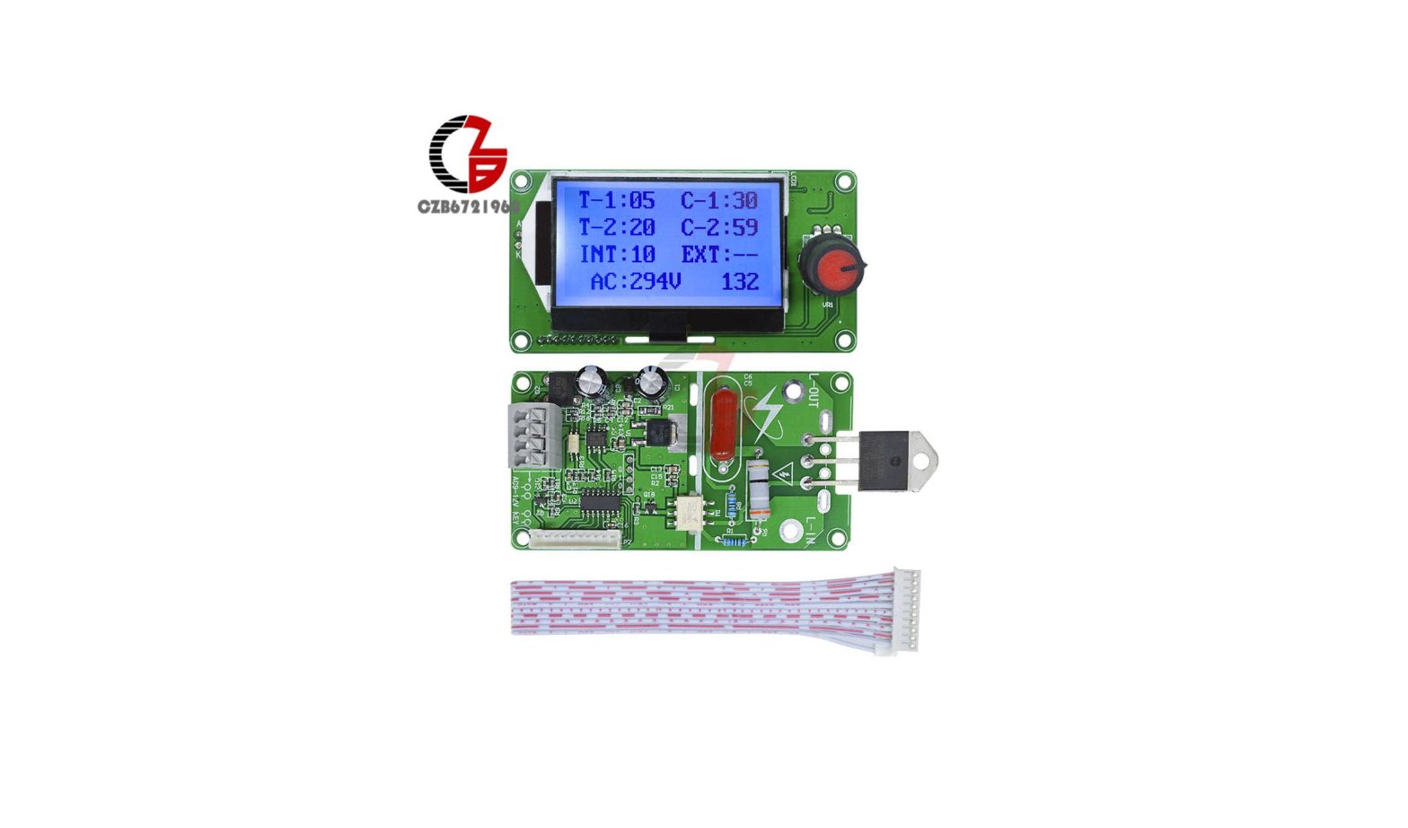
The spot welder control module is developed for DIY or simple battery welder. It is mainly used for single battery or battery group nickel plated sheet welding, such as 18650 lithium battery nickel plating 0.15 and 0.2mm steel sheet, 500W transformer can be welded directly. It is intended to weld other battery materials and different thickness, such as polymer battery electrode without nickel plating, must be combined with sufficient power transformer to weld.This module includes main board and display board, optional 40A and 100A bidirectional silicon control rectifier (SCR), does not include welding transformers, welding pen and other matching tools.
Scope of use
- DIY or simple battery welder development welding.
- Welding of a single battery or battery pack.
Functional overview
- Can be set to save the last operation, the module double pulse trigger, turn off any set of trigger time, you can change double pulse to single pulse trigger.The need for a single pulse can also select SWM-101 digital tube model.
- The main board and the display operation panel are separated, and the outer casing can be flexibly assembled.
- Multi-group data 12864 visual display, intuitive operation, convenient, single encoder parameter adjustment can make the operation simple and fast.
- With grid voltage compensation, the output of compensation can be automatically adjusted according to the change of power supply, and the electric voltage of about 1 second can be displayed when triggered, so that the effective heat of welding is consistent with the welding parameters, and the welding spot is uniform.
- With 0-9999 welding counting function, with 5 groups of sample storage parameters, can be stored even the electricity power is off, the number of wleding could be seen just by a glance.
- Time input 0-99 cycle (1 cycle is 20ms, for example, the adjustment value is 50, which is the welding time 1 second.), the stop time between 2 weldings is 0-99 cycles (1 cycle is 20ms, such as interval value 50, It is the interval of 1 second.) adjustable. Welding strength 30%-99% is adjustable.
- The module can isolate the strong and weak electricity by optical coupling, and design a reliable circuit for zero-crossing detection and voltage detection to ensure the accurate phase shift of silicon control rectifier (SCR), which can be compatible with 40A-100A bidirectional silicon control rectifier (SCR).
- 9-12 V AC power input (using AC transformers, other such as DC, can cause zero-crossing detection failure, can not trigger.)
- The power input and external trigger adopt convenient and quick welding free terminal, the external trigger can be diversified, such as normal switch, foot switch, external signal source input, etc., the software has anti-lock state, triggering to the end of welding, for one round. For example, the pedal switch has been trampled all the time, can only trigger one round.
Usage method
- Voltage calibrationThe module has the network voltage compensation function, so the voltage calibration must be carried out when the first machine is installed, and in the future, as long as the module power transformer is not replaced, there is no need to recalibrate. Of course, when you feel that the display voltage is wrong and it can be calibrated. The following are the mains voltages that are not calibrated and displayed during operation:
 Calibration operation: press and hold the encoder to power the module to enter the calibration interface, the first flicker can be adjusted by the encoder once, after the third bit, the short press encoder can enter the operation interface. For example, the measured voltage is 220 V, the calibration interface can be set to 220.The following is the trigger interface to display the local electrical voltage:
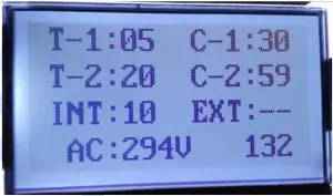
 - Display interfaceT→Time C→Current INT→Interval EXT→ExtractInterval: idle time between two welds.
- Numerical adjustment: long press encoder, enter adjustment interface, when numerical corresponding value double digital flicker,Short press encoder, with a single digit flickering left or right to adjust the value,Short press the encoder to change the next digit.When the double digit flashes, the left or right rotary encoder changes the next parameter adjustment.When the count value is greater than 0, rotate the encoder to the counting position, short press the encoder, left-hand or right-hand encoder to clear.When “exit” flashes, press the encoder to exit the adjustment interface. When exiting the interface, the encoder is double-clicked within 1 second, the current parameter content can be saved as the next call parameter (template save parameter), and the save position corresponds to the calling position.The save position is 0-4, and when it exceeds the maximum value, it is overwritten from 0.
- Extracting saved parameters(EXT→Extract):when “▬ ▬” is displayed, it indicates that the current parameter is changeable and can be adjusted freely.The last adjustment is saved by default. When the calling parameter value is 0-4, it means that the current parameter comes from the template saving parameter (double-click encoder within 1 second).The current parameter can not be changed except the calling state (EXT) can be changed and the count value can be cleared to zero. Other parameters cannot be changed.
- Wiring diagramMicrowave oven transformer Welding pen Control panel Normally open switch
- Plate size and mounting hole position
 Calibration operation: press and hold the encoder to power the module to enter the calibration interface, the first flicker can be adjusted by the encoder once, after the third bit, the short press encoder can enter the operation interface. For example, the measured voltage is 220 V, the calibration interface can be set to 220.
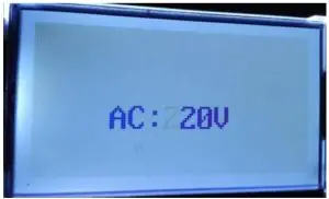 The following is the trigger interface to display the local electrical voltage:
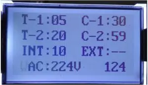
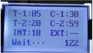 T→Time C→Current INT→Interval EXT→ExtractInterval: idle time between two welds.
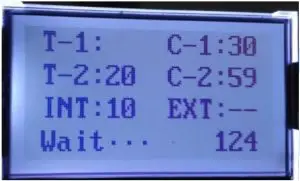 Short press encoder, with a single digit flickering left or right to adjust the value,
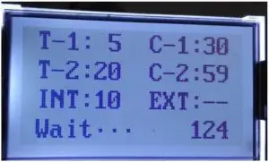 Short press the encoder to change the next digit.When the double digit flashes, the left or right rotary encoder changes the next parameter adjustment.When the count value is greater than 0, rotate the encoder to the counting position, short press the encoder, left-hand or right-hand encoder to clear.When “exit” flashes, press the encoder to exit the adjustment interface. When exiting the interface, the encoder is double-clicked within 1 second, the current parameter content can be saved as the next call parameter (template save parameter), and the save position corresponds to the calling position.The save position is 0-4, and when it exceeds the maximum value, it is overwritten from 0.
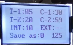
 Microwave oven transformer Welding pen Control panel Normally open switch
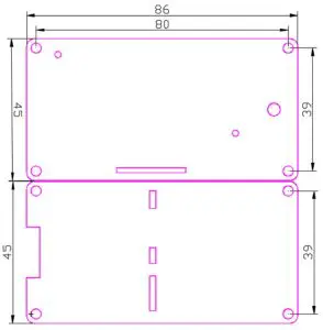
Precautions for use
- This module DIY needs to have certain electrician knowledge, if you are complete freshman, please refer to the electrician’s knowledge before you start. Pay attention to the safe use of the high voltage part during installation. When the usage frequency and power are high, silicon control rectifier requires external radiator to disspate heat.
- The power of the module driving load depends on the power of silicon control rectifier (SCR). BAT41 (40A) can carry a microwave oven transformer, BAT100 (100A) can carry two microwave oven transformers, and the recommended one for Loop transformer is 100A.
- Do not know the welding time and power of the welded parts, it is recommended that the welding time and power be adjusted from small to upper to avoid damage to the welding pen.
Fault cause and troubleshooting
- The electricity supply does not match the actual electricity voltage: re-voltage calibration.
- The solder joint is not secure or soldered: adjust welding time and power until satisfactory results are achieved.
[xyz-ips snippet=”download-snippet”]