Air Live Dual Relay Wall Switch User Manual
FCC Interference Statement
This equipment has been tested and found to comply with the limits for a Class digital device, pursuant to Part 15 of the FCC Rules. These limits are designed to provide reasonable protection against harmful interference in a residential installation.
This equipment generates uses and can radiate radio frequency energy and, if not installed and used in accordance with the instructions, may cause harmful interference to radio communications.
However, there is no guarantee that interference will not occur in a particular installation. If this equipment does cause harmful interference to radio or television reception, which can be determined by turning the equipment off and on, the user is encouraged to try to correct the interference by one of the following measures:
- Reorient or relocate the receiving antenna.
- Increase the separation between the equipment and receiver.
- Connect the equipment into an outlet on a circuit different from that to which the receiver is connected.
- Consult the dealer or an experienced radio/TV technician for help.
This device complies with Part 15 of the FCC Rules. Operation is subject to the following two conditions:
- This device may not cause harmful interference, and
- This device must accept any interference received, including interference that may cause undesired operation.
FCC Caution: Any changes or modifications not expressly approved by the party responsible for compliance could void the user’s authority to operate this equipment. This transmitter must not be co-located or operating in conjunction with any other antenna or transmitter.
Disposal![]() This marking indicates that this product should not be disposed with other household wastes throughout the EU. To prevent possible harm to the environment or human health from uncontrolled waste disposal, recycle it responsibly to promote the sustainable reuse of material resources. To return your used device, please use the return and collection systems or contact the retailer where the product was purchased. They can take this product for environmental safe recycling.
This marking indicates that this product should not be disposed with other household wastes throughout the EU. To prevent possible harm to the environment or human health from uncontrolled waste disposal, recycle it responsibly to promote the sustainable reuse of material resources. To return your used device, please use the return and collection systems or contact the retailer where the product was purchased. They can take this product for environmental safe recycling.
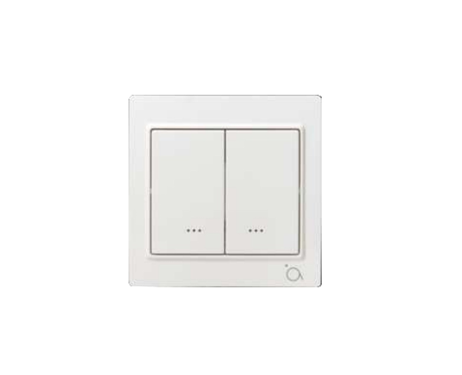
Overview
The SA-104, is a Z-Wave plus compliant Z-Wave Dual Relay Wall Switch to replace your current light switch with a Z-Wave included one. The Z-Wave command is translated to a switching command. The wall mounted switch is a component of the lighting control system. This wall mounted switch is designed to work with other Z-Wave enabled devices. Z-Wave nodes of other types can be added to the system and act as repeaters if they support this function of repeating the signal received to other modules in the system. As part of a Z-Wave network, this switch will also act as a wireless repeater to insure that commands intended for another device in the network are received. This is useful when the device would otherwise be out of the radio range of the Z-Wave controller. There are no field repairable assemblies on this unit. If service was needed, the unit must be returned where purchased. This product can be included and operated in any Z-WaveTM network with other Z-WaveTM certified devices from other manufacturers and/or other applications. All non-battery operated nodes within the network will act as repeaters regardless of vendor to increase reliability of the network.The device adopts the Z-WaveTM 500 series chip, when your Z-WaveTM network system is all made by Z-WaveTM 500 series devices. The network system will have the advantages.
Adding to Z-WaveTM Network
Note: This switch must be “Included in the Network” where it will be permanently installed. The proper operation of the SA-104 in the mesh network is dependent on knowing its location with respect to other nodes. You cannot “test bench” configure this switch and then install it.
First time adding, When first power is applied, its LED flashes on and off alternately and repeatedly at 1-second intervals. It implies that it has not been assigned a node ID yet and start the auto inclusion. To add the device into the Z-WaveTM network, first make sure the primary controller is in the inclusion mode.
Auto InclusionIn the front casing, there is an On/Off button with LED indicator which is used to toggle switch on and off or carry out inclusion, exclusion, reset or association. When first power is applied, its LED flashes on and off alternately and repeatedly at 1-second intervals. It implies that it has not been assigned a node ID and cannot work with Z-Wave enabled devices. The table below lists an operation summary of basic Z-Wave function. Please refer to the instructions for your Z-WaveTM certificated primary controller to access the Setup function, and to include/exclude/associate devices.
Note: Auto inclusion timeout is 2 minute during which the node information of explorer frame will be emitted once several seconds. Unlike “inclusion” function as shown in the table below, the execution of auto inclusion is free from pressing the Include/Exclude button in on the front case.
The table below lists an operation summary of basic Z-Wave functions. Please refer to the instructions for your Z-WaveTM Certificated Primary Controller to access the Setup function, and to include/exclude/associate devices.
| Function |
Description |
| No node ID | The Z-Wave controller does not allocate a node ID to the Switch |
| Inclusion (Add) |
|
| Exclusion (Remove) |
|
| Node ID has been excluded. | |
| Reset |
|
| Association |
|
|
LED Indication
To distinguish what
| State Type |
LED Indication |
| No node id | 1-second on, 1-second off |
| Inclusion (Add) | Press on, for off, Press off, for on |
| Exclusion (Remove) | Press on, for off, Press off, for on |
| Node ID Excluded | 1-second on, 1-second off |
| Reset | Press on, for off, Press off, for on |
| Association | Press on, for off, Press off, for on |
Choosing a Suitable Location
- The SA-104 Z-Wave Wall Switch can replace your original Switch the location there for would be the same as your original wall switch. Do not place the switch in a wet environment.
Installation and Basic Operation
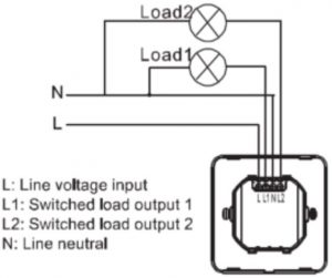
Step 1 Connection diagram of SA-104.
Note: A Neutral wire is required for the correct operation.
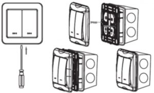
Step 2 Removal of front cover.
Step 3 Basic Operation
Basic Operation (Local Control)The switch allows the user to:
- The ON or OFF the attached load.
- Include or exclude the module from the Z-Wave system.
- Control other Z-Wave enabled devices.Also, when a controller prompts you to “Send Node ID” or to “Press Button on Unit” quickly tap the switch On or OFF three times to satisfy those instructions.
- Tapping top of left switch turns the load1 attached ON.
- Tapping bottom of left switch turns the load1 attached OFF.
- Tapping top of right switch turns the load2 attached ON.
- Tapping bottom of right switch turns the load2 attached OFF.
Caution: When dimmed at the lowest setting, even though the load looks like its off, it still has power. Tap bottom of switch to turn off completely. It is best to turn off the power at the circuit breaker to service the load. Note: Upon restoration of power after a power loss, the switch returns to previous known state.
LED IndicationThe LED on the switch will turn on when the load attached is off, to act as a night light. However, the LED can be user configured to turn on when the load attached is on the switch will flicker its LED when it is transmitting to any of its 4 groups. This can be changed if desired. See “LED transmission indication Parameter”
Remote controlThe switch will respond to BASIC and BINARY commands that are part of the Z-Wave system. Refer to your controller’s instructions as to whether your controller can transmit those commands.
Advance operation all on/all offThe switch support the all on/all off commands. The switch can be set to respond to all on and all off commands 4 different ways. Refer to your controller for information on how to set the switch to operate in the manner you desire. Some controllers may be only able to set certain settings of all on /all off response. The 4 different ways the switch can be setup to respond to all on and all off
Association and Parameter
Association SetupAssociationThe switch supports the association command.The switch can be set to control other Z-Wave devices. Those devices must be installed in their permanent location.You can turn on and off, and even dim other Z-Wave devices once they are “associated” into 1 of 4 groups within the switch.Each group is turned on or off (or dimmed) by tapping or holding the switch a differing amount of times.
Group 1 Control: If you associate a Z-Wave device into Group 1, you can turn that device ON and OFF by tapping the top or bottom of the right switch, you can brighten or dim devices by pushing and holding the top of the right switch Dim by pushing and holding the bottom of the right switch. The load attached to the switch is not affected. The LED on the right switch will indicate the status of Group 1. Group 1 will be polled at a specific interval and the LED on the right switch will indicate the status of Group 1. The polling interval can be configured. The Group1 name is lifeline (Profile MSB=0x00,Profile LSB= 0x01).
Group 2 Control: If you associate a Z-Wave device into Group 2, you can turn that device ON or OFF by tapping the top or bottom of the left switch twice. You can brighten or dim devices by tapping the switch once then push and hold the top or bottom of the left switch. The load attached to the switch is not affected. The LED on the left switch will indicate the status of Group 2. Group 2 will be polled at a specific interval and the LED on the left switch will indicate the status of Group 2. The polling interval can be configured. The Group2 name is On/Off Dimmer 1(Profile MSB=0x20, Profile LSB=0x01).
Group 3 Control: If you associate a Z-Wave device into Group 3, you can turn that device ON or OFF by tapping the top or bottom of the right switch twice. You can brighten or dim devices by tapping the switch once then push and hold the top or bottom of the right switch. The load attached to the switch is not affected. The Group3 name is on off dimmer 2 (Profile MSB=0x20, Profile LSB=0x02).
Group 4 Control: If you associate a Z-Wave device into Group 4, that device will be commanded to turn on or off when the switch is commanded to turn on or off Caution: The switch will not transmit to Z-Wave devices in Group 4 if it is already in the state that the Z-Wave command commanded it to. You can associate up to 5 Z-Wave devices into each of these groups. For instructions on how to “associate” a Z-Wave device into one of these groups, refer to your wireless controller instructions. (If you are using the z-wave controller, refer to the setup menu, association section). A note about dimming, if you combine Z-Wave enabled dimmers and other types of Z-Wave devices in a group, place a Z-Wave enabled dimmer into the empty group first to ensure that the dimming operates correctly. The Group4 name is wireless. (Profile MSB=0x20, Profile LSB=0x03)
Configuration Parameter
|
Configuration Parameter |
Function |
Value |
Default Value |
Size (Byte) |
|
1 |
Night Light | 0 – 1 | 1 |
1 |
|
2 |
Memory Function | 0 – 1 | 1 |
1 |
|
3 |
Invert Switch | 0 – 1 | 0 |
1 |
|
4 |
LED Transmission Indication | 0 – 2 | 1 |
1 |
| 5 | Suspend Group 4 | 0 – 1 | 0 |
1 |
Parameter DescriptionNight light
- Parameter NO:1
- Length: 1 Byte
- Valid values=0 or 1 (default value is 1)
The LED on the switch will by default, turn ON when the load attached is turn OFF. To make the LED turn ON when the load attached is turn ON instead, set parameter 1 to a value of 1.
Memory function
- Parameter NO:2
- Length: 1 Byte
- Valid values=0 or 1 (default value is 1)
Stated in the above form, switch by default value is 1,when the value is 0, switch memory function not open; when the value is 1, Open switch memory function.
Invert switch
- Parameter NO:3
- Length: 1 Byte
- Valid values=0 or 1 (default value is 0)
To change the top of the switch to OFF and the bottom of the switch ON, set parameter 3 to 1.Note: if you invert the switches and also install the product upside down, remember the load will now be controlled by the right, not the left switch.
LED transmission Indication
- Parameter NO:4
- Length: 1 Byte
- Valid values = 0, 1, 2, (default value is 1)
The switch will flicker its LED when it is transmitting to any of its 4 groups. This flickering can be set to not flicker at all (set to 0), to flicker the entire time it is transmitting (set to 2), or to flicker for only 1 second when it begins transmitting (set to 1). By default, the switch is set to flicker for only 1 second. Each configuration parameter can be set to its default setting by setting the default bit in the configuration set command. see your controller’s instructions on how to do this (and if it supports it). All configuration commands will be reset to their default state when the switch is reset from the Z-Wave system.
Suspend group 4
- Parameter NO:5
- Length:1 Byte
- Valid values = 0 or 1(default value is 0)
You may wish to disable transmitting commands to Z-Wave devices that are in Group 4 without “disassociating” those devices from the group. Setting parameter 5 to the value of 1 will stop the switch from transmitting to devices that are “associated” into Group 4.
Specifications
| Specification | |
| Model | SA-104 Dual Relay Wall Switch |
| Z-Wave Standard | Z-wave plus |
| Z-Wave Frequency | CE:868.40MHz,869.85MHz |
| Maximum Transmission Distance | 40M (indoor) 100m (open space) |
| Supply Voltage | 230 VAC |
| Maximum Output Current | 6A (Resistive Load) |
| Maximum Output Power | 1380 W (Resistive Load) X 2 |
| LED Indicator | 2 x LED (one per paddle) |
| Dimension and Environment | |
| Dimensions | 86(L) x 86(W) x 24(H) mm |
| Operating Temperature | 0 ~ 40° C |
** Specifications are subject to change and improvement without notice.
OvisLink Corp.http://www.airlive.com/TEL: +886 2 2218 6888FAX: +886 2 2918 6988
References
[xyz-ips snippet=”download-snippet”]