Air Live Smoke Sensor
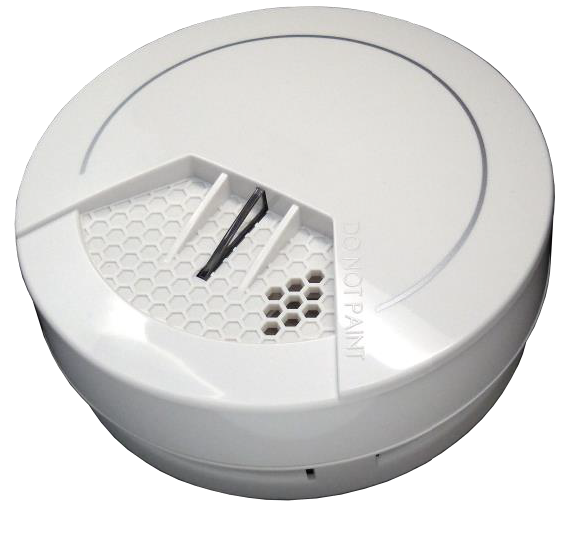
The Z-Wave Plus Smoke Sensor SI-104 is designed to give early warning of developing fires by giving off the alarm sounds from its build-in alarm horn, based on Z-WaveTM technology.It is the Z-WaveTM plus product, it support the security, OTA… those newest features of the Z-WaveTM technology. Z- Z-WaveTM is a wireless communication protocol designed for home automation, specifically to remotely control applications in residential and light commercial environments. The technology uses a low-power RF radio embedded or retrofitted into home electronics devices and systems, such as lighting, home access control, entertainment systems and household appliances.
This product can be included and operated in any Z-WaveTM network with other Z-WaveTM certified devices from other manufacturers and/or other applications. All non-battery operated nodes within the network will act as repeaters regardless of vendor to increase reliability of the network.
The device adopts the Z-WaveTM 500 series chip, when your Z-WaveTM network system is all made by Z-WaveTM 500 series devices. The network system will have the advantages as below.
- Concurrent multi-channel support reduces external interference.
- Better RF range, improve about 10 meters in indoor.
- Support 100 Kbps transmit speed, speed up communication.
Add to/Remove from Z-WaveTM Network
There is one button on the device. It can be used to add, remove, reset or association from Z-WaveTM network.In the first time, add the device into the Z-WaveTM network. First, make sure the primary controller is in the add mode. And then power on the device, just take out the insulation Mylar in the back side of the device. The device will auto start the NWI (Network Wide Inclusion) mode. And it should be included in 5 seconds. You will see the LED light ON one second.
Notice: Including a node ID allocated by Z-WaveTM Controller means “Add” or “Inclusion”.Excluding a node ID allocated by Z-WaveTM Controller means “Remove” or “Exclusion”.
| Function | Description |
|
Add |
1. Have Z-WaveTM Controller entered inclusion mode.
2. Pressing TEST Button three times within 1.5 seconds to enter the inclusion mode. 3. After add successful, the device will wake to receive the setting command from Z-WaveTM controller about 20 seconds. |
|
Remove |
1. Have Z-WaveTM Controller entered exclusion mode.
2. Pressing TEST Button three times within 1.5 seconds to enter the exclusion mode. Node ID has been excluded. |
| Reset | Notice: Use this procedure only in the event that the primary controller is lost or otherwise inoperable.
1. Pressing TEST Button four times within 1.5 seconds and do not release the tamper key in the 4th pressed and the red LED will light ON. 2. After the red LED flash 9 times, release the button within 2 seconds. 3. IDs are removed and all settings will reset to factory default. |
|
Association |
1. Have Z-WaveTM Controller entered association mode.
2. Pressing TEST Button three times within 1.5 seconds to enter the association mode. Note: The device supports 1 group. This group is for receiving the report message, like triggered event etc. These groups support 8 nodes maximum. |
| Failed or success in add/remove the node ID can be viewed from Z-WaveTM Controller. |
Notice 1: Always RESET a Z-WaveTM device before trying to add it to a Z-WaveTM network
Notice 2: When the device into NWI mode, the sensor functionality will useless. The NWI mode will timeout after 30 seconds. You can press the tamper key 3 times to abort the NWI mode.
Z-WaveTM Notification
After the device adding to the network, it will wake-up once per day in default. When it wake-up it will broadcast the “Wake Up Notification” message to the network, and wake-up 10 seconds for receive the setting commands.The wake-up interval minimum setting is 30 minutes, and maximum setting is 120 hours. And the interval step is 30 minutes.
If the user wants to wake-up the device immediately, please press the tamper key once. The device will wake-up 10 seconds
Z-WaveTM Message Report
When the smoke sensor detects, the device will report the trigger event and also report the battery status.
In default the device will using Notification Report to represent the trigger event, it can be changed to Sensor Binary Report by setting the configuration NO. 7 Bit4 to 1.
Smoke Detected/Test Report:When the Smoke Sensor detects smoke, the device will unsolicited to send the smoke detected (0x02) report to the nodes in the group 1. When the device is in alarm test mode, the device will unsolicited to send the Smoke Sensor test (0x03) report to the nodes in the group 1.
| Notification Type: Smoke (0x01)
Event: Smoke detected, Unknown Location (0x02) Smoke Alarm Test (0x03) |
| Sensor Binary Report (V2) |
| Sensor Type: Smoke (0x02) Sensor Value: 0xFF |
Tamper Report
When the tamper is pressed, the device will into the alarm state. In that state, if tamper is released, the yellow LED will light on and the device will unsolicited to send the report to the nodes in the group 1
| Notification Report (V4) |
| Notification Type: Home Security (0x07)
Event: Tampering. Product covering removed (0x03) |
| Sensor Binary Report (V2) |
| Sensor Type: Tamper (0x08) Sensor Value: 0xFF |
Notice : When the event triggered, the device will report the messages to the nodes in the group 1. The messages also include the tamper status
Power Up Procedure
NWI:When the device power on, the device will check is it already adding to the network? If doesn’t, press the button to start the NWI mode. Until timeout or the device successful to inclusion by controller. NWI mode can be aborted by pressing the button 3 times
Wake: When the device power on, the device will wake about 20 seconds. In this duration, the controller can communicate with the device. Normally the device is always sleeping to save the battery energy.
Over The Air (OTA) Firmware Update
The device supports the Z-Wave firmware update via OTA. Let the controller into the firmware update mode, and then press the button once to start the update.Please don’t remove the battery, otherwise it will cause the firmware broken, and the device will no function. After updated finish, it is recommended that the user power up the device.
Caution: After remove the battery, please wait about 30 seconds, and then re-install the battery.
Security Network
The device supports the security function. When the device included with a security controller, the device will auto switch to the security mode. In the security mode, the follow commands need using Security CC wrapped to communicate, otherwise it will not response.
COMMAND_CLASS_BATTERYCOMMAND_CLASS_NOTIFICATION_V4COMMAND_CLASS_ASSOCIATION_V2COMMAND_CLASS_CONFIGURATIONCOMMAND_CLASS_SENSOR_BINARY_V2COMMAND_CLASS_WAKE_UP_V2
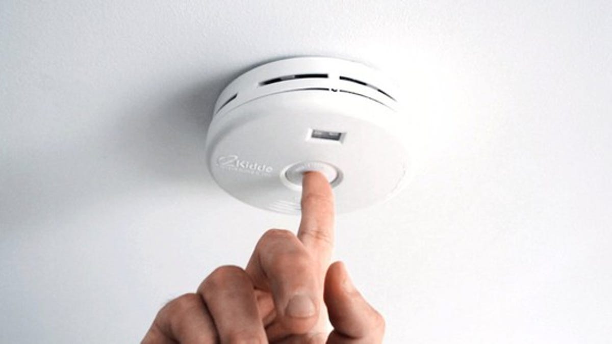
Test Alarm
Test the sensor by pushing firmly on the test button for around 2 seconds until the horn sounds, the sound pattern is 3 beeps, pause, and then 3 beeps with red LED flashing continuously and rapidly, and the controller will receive Smoke alarm test notification. If the Smoke Sensor beeps three with yellow LED flashing three times in 43 seconds, it indicates the Smoke Sensor is not working properly, it requires to be repaired.
This is the only way to make sure that the Smoke Sensor device is working properly. If the device fails to test properly, have it repaired or replaced immediately. If you suspect that your Smoke Sensor does not go into alarm, test it by pressing the test button to ensure if it works properly.
Notice : To keep the Smoke Sensor in good working condition, testing the device weekly is necessary.
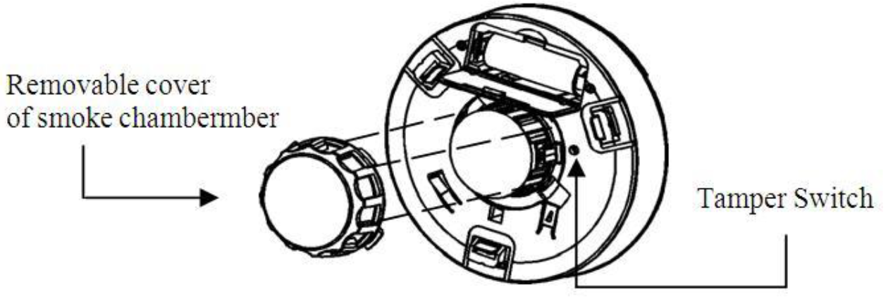
Tamper Switch Feature
If the Smoke Sensor is not mounted into the bracket properly, the tamper function is triggered and the yellow LED is steadily on. You will hear temporal three sound with yellow LED steadily on until Smoke Sensor is mounted back into bracket properly
Battery Installation
If your controller receive low battery alarm and, this signal means that the Smoke Sensor’s battery is weak. When the device report the low battery message. The user should replace the battery to new one to secure your protection. The battery type is CR123A, 3.0V.The way to open the front cover please follow below steps:
- Open battery compartment.
- Install battery into compartment and make sure the “+” and “-”ends of each battery are aligned properly.
- After battery is installed in compartment, you will hear a chirp which indicates the device is receiving battery power.
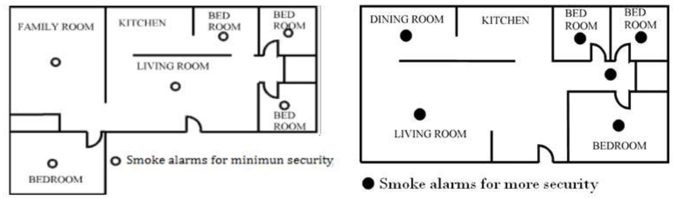
Choosing a Suitable Location
For complete coverage in residential units, Smoke Sensors should be installed in all rooms, halls, storage areas, basements and attics in each family living unit. Minimum coverage is one sensor on each floor and one in each sleeping area.
- Install Smoke Sensor as close to the center of ceiling as possible. If this is not practical, put the sensor on the ceiling, no closer than 4inches(10 cm) from any wall or corner.
- If ceiling mounting is not possible, put wall-mounted sensors between 4 and 6 inches(10~15 cm) from the ceiling.
- If some of your rooms have sloped, peaked, or gabled ceilings, try to mount sensors 3 feet(0.9 meter) measure horizontally from the highest point of ceiling.
Nuisance alarms take place when Smoke Sensors are installed where they will no work properly. To avoid nuisance alarms, do not install Smoke Sensors in the following situations:
- Combustion particles are the by-products of something that is burning. Thus, in or near areas where combustion particles are present you do not install the Smoke Sensors to avoid nuisance alarms, such as kitchens with few windows or poor ventilation, garages where there may be vehicle exhaust, near furnaces, hot water heaters, and space heaters.
- Do not install Smoke Sensors less than 20 feet (6 meters) away from places where combustion particles are normally present, like kitchens.If a 20-foot distance is not possible, e.g. in a mobile home, try to install the alarm as far away from the combustion particles as possible, preferably on the wall. To prevent nuisance alarm alarms, provide good ventilation in such places.
- In very dusty or dirty areas, dirt and dust can build up on the alarm’s sensing chamber, to make it overly sensitive. Additionally, dust or dirt can block openings to the sensing chamber and keep the alarm from sensing smoke.
- Near fluorescent lights, electrical “noise” from fluorescent lights may cause nuisance alarms. Install Smoke Sensor at least 5 feet (1.5 meters) from such lights.
Installation
- At the place where you are going to install your Smoke Sensor, draw a horizontal line six inches long.
- Remove the mounting bracket from your device by rotating it counterclockwise.
- Place the bracket so that the two longest hold slots are aligned on the line. In each of keyhole slots, drawing a mark to locate a mounting plug and screw.
- Remove the bracket.
- Drill two holes at the marks and insert plastic wall plugs. Put the Smoke Sensor away from plastic dust.
- Attach the bracket to the wall. Line up the slots of the bracket and the Smoke Sensor. Push the sensor onto the mounting bracket on turn it clockwise to fix it into the place. Pull onward on the Smoke Sensor to make sure it is securely attached to the mounting bracket.


Z-Wave Configuration Settings
Notice:All of the configuration, the data size is 1.The configuration mark with star(*), means after the remove the setting still keep, don’t reset to factory default. Unless the user execute the “RESET” procedure.The reserve bit or not supported bit is allowed any value, but no effect.
| NO. | Name | Def. | Valid | Description |
| 7(*) | Customer Function | 4 | All | Customer function switch, using bit control. |
| 0 | Bit0: Reserve. | |||
| 0 | Bit1: Reserve. | |||
| Bit2: Reserve. | ||||
| Bit3: Reserve. | ||||
| Bit4: Notification Type,
0: Using Notification Report. 1: Using Sensor Binary Report. |
||||
| Bit5: Reserve. | ||||
| 0 | Bit6: Reserve. | |||
| 0 | Bit7: Reserve. | |||
| 10 | Auto Report Battery Time | 12 | 0 ~
127 |
The interval time for auto report the battery level.
0 means turn off auto report battery. Each tick means 30 minutes. The default value is 12 (6 hours). |
Z-Wave Supported Command Class
COMMAND_CLASS_ZWAVEPLUS_INFO_V2COMMAND_CLASS_BATTERYCOMMAND_CLASS_NOTIFICATION_V4COMMAND_CLASS_ASSOCIATION_V2COMMAND_CLASS_CONFIGURATIONCOMMAND_CLASS_MANUFACTURER_SPECIFIC_V2 COMMAND_CLASS_VERSION_V2COMMAND_CLASS_SENSOR_BINARY_V2COMMAND_CLASS_WAKE_UP_V2COMMAND_CLASS_ASSOCIATION_GRP_INFO COMMAND_CLASS_POWERLEVELCOMMAND_CLASS_DEVICE_RESET_LOCALLY COMMAND_CLASS_SECURITYCOMMAND_CLASS_FIRMWARE_UPDATE_MD_V2
Specifications
Power by CR123A lithium battery.
Signal (Frequency):SI-104: 868.40 MHz, 869.85 MHz(EU),SI-104: 908.40 MHz, 916.00 MHz(US),SI-104: 922~927 MHz(JP/TW),SI-104: 921.40 MHz, 919.80 MHz(ANZ),SI-104: 869.00 MHz(RU),SI-104: 865.20 MHz(IN),SI-104-IL:916.00 MHz(IL),
Range:Minimum 40 meters indoor, 100 meters outdoor line of sight.
Operating Temperature: -10oC ~ 40oCFor indoor use only.Specifications subject to change without notice due to continuing product improvement.
Copyright & DisclaimerNo part of this publication may be reproduced in any form or by any means, whether electronic, mechanical, photocopying, or recording without the written consent of OvisLink Corp.OvisLink Corp. has made the best effort to ensure the accuracy of the information in this user’s guide. However, we are not liable for the inaccuracies or errors in this guide. Please use with caution. All information is subject to change without noticeThis product contains some codes from GPL. In compliance with GPL agreement, AirLive will publish the GPL codes on our website. Please go to www.airlive.com and go to the“Support->GPL” menu to download source code.All Trademarks are properties of their respective holders.
FCC Interference Statement
This equipment has been tested and found to comply with the limits for a Class B digital device, pursuant to Part 15 of the FCC Rules. These limits are designed to provide reasonable protection against harmful interference in a residential installation. This equipment generates uses and can radiate radio frequency energy and, if not installed and used in accordance with the instructions, may cause harmful interference to radio communications. However, there is no guarantee that interference will not occur in a particular installation. If this equipment does cause harmful interference to radio or television reception, which can be determined by turning the equipment off and on, the user is encouraged to try to correct the interference by one of the following measures:
- Reorient or relocate the receiving antenna.
- Increase the separation between the equipment and receiver.
- Connect the equipment into an outlet on a circuit different from that to which the receiver is connected.
- Consult the dealer or an experienced radio/TV technician for help.
This device complies with Part 15 of the FCC Rules. Operation is subject to the following two conditions:
- This device may not cause harmful interference, and
- This device must accept any interference received, including interference that may cause undesired operation.
FCC Caution: Any changes or modifications not expressly approved by the party responsible for compliance could void the user’s authority to operate this equipment.This transmitter must not be co-located or operating in conjunction with any other antenna or transmitter.
WarningDo not dispose of electrical appliances as unsorted municipal waste, use separate collection facilities. Contact your local government for information regarding the collection systems available. If electrical appliances are disposed of in landfills or dumps, hazardous substances can leak into the groundwater and get into the food chain, damaging your health and well-being.When replacing old appliances with new once, the retailer is legally obligated to take back your old appliance for disposal at least for free of charge.

References
[xyz-ips snippet=”download-snippet”]