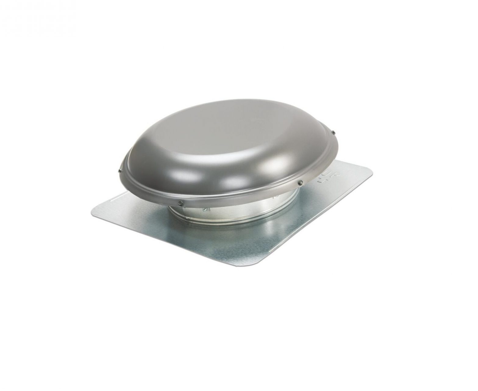
AIR VENT INC High Efficiency Powered Attic Fan

WARNING:Read all warning messages and instructions before starting installation of this fan. Failure to follow these safety instructions can result in injury or even death. If you need assistance in understanding these instructions or have questions or comments, please call (800) 247-8368.
ELECTRICAL HAZARDS
DANGER: The electrical installation and wiring of this fan must be done by a qualified electrician in accordance with all local codes and standards, including fire-rated construction. Failure to do the installation properly can result in fire or even death.NOTE: A few hours of operation without apparent problems does not necessarily imply that the installation is safe.DANGER: Do not use this fan with any solid state speed control device. Use of a solid state speed control can result in a fire causing injury or death.DANGER: Watch out for existing electrical wiring and other utility wires or pipes when selecting a location for the fan. Do not install the fan where there is electrical wiring in the way. Select another location or have a qualified electrician move the wiring to a different location.DANGER: Before servicing or cleaning the unit, switch the power off at the service panel and lock the service panel to prevent the power from being switched on accidentally. When the service disconnecting means cannot be locked, securely fasten a prominent warning device, such as a tag, to the service panel.
LACERATION HAZARDS
DANGER: This fan has an unguarded fan blade. Do not use in locations which are readily accessible to people or animals. Do not let children play in an attic where this fan has been installed. Contact with this fan while in operation can result in injury or even death.DANGER: Switch the power off at the service panel and lock the service panel before servicing the motor. When the service disconnecting means cannot be locked, securely fasten a prominent warning device, such as a tag, to the service panel. This fan is thermostatically controlled – it may start at any time if the power is not switched off at the service panel. Contact with the fan blades while the fan is operating can result in serious injury.WARNING: This product has sharp metal edges that can cut your hands. Wear canvas work gloves while handling the fan during installation.OTHER HAZARDSDANGER:This fan is for general ventilating use only. Do not use to exhaust hazardous or explosive materials or vapors. Use of this fan to exhaust hazardous, explosive or flammable materials may result in a fire or explosion, causing injury or death.
HE15 HIGH EFFICIENCY POWERED ATTIC FAN INSTALLATION INSTRUCTIONS
NOTE: Air intake openings are necessary for proper exhaust operation. Best results will be obtained if these openings are located around the eaves. Under eave soffit grills or continuous soffit vents are suggested.
Sq. Ft. of Air IntakeOpening Needed4.4
ModelHE15
TOOLS NEEDED: 1 gang steel junction box with at least one 1/2″ knockout and a cover plate, electric drill, tape measure, hammer & nails, utility knife and pencil, jig or sabre saw, roofing nails, phillips screw driver, adjustable wrench, wire cutter, work gloves and safety glasses.
TOOLS NEEDED: 1 gang steel junction box with at least one 1/2″ knockout and a cover plate, electric drill, tape measure, hammer & nails, utility knife and pencil, jig or sabre saw, roofing nails, phillips screw driver, adjustable wrench, wire cutter, work gloves and safety glasses.
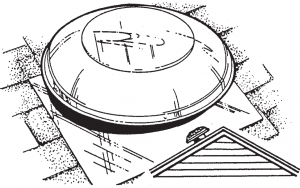
- POSITIONING THE POWER ATTIC VENTILATOR ON THE ROOF:Set the unit approximately in the center of the roof close to the ridgeline. Position the ventilator so that the unit can only be seen from one side of the house.

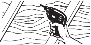
- DRILL THE GUIDE HOLE:Measure the distance to the ridgeline and to one end of the roof. Transfer these exterior dimensions to inside the attic. Next locate a center position between two rafters (inside the attic) as near as possible to the outside measurements. Drill a guide hole through the roof from inside that is an equal distance between the two rafters. Place a marker through the roof for quick identification while on the roof.
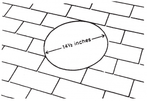
- CUTTING THE HOLE:Draw a circle 14.5″ in diameter using the guide hole as the center. A template is provided on the back of the carton for drawing the circle.
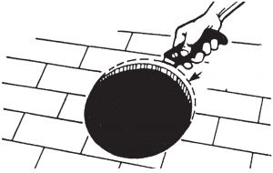
- CUTTING THE HOLE IN THE ROOF:Using a sabre saw, cut and remove all roof shingles (and deck) inside the 14.5″ diameter circle. Next cut an extra 1 inch off the top half of the hole (shingles only) to allow room for placing and positioning the flange.Do not cut through any rafters. Cutting a rafter may cause your roof to sag.
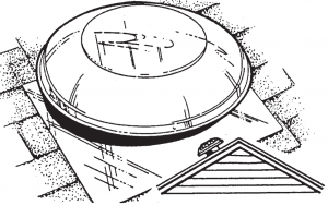
- SECURING THE BASE:Make sure the base flange parallels the ridgeline of the roof. The embossed arrow and word UP should be pointing towards the ridgeline. Slip the upper half of the flange under the shingles.Center the unit over the hole. Attach the flange securely to the roof using roofing nails around the perimeter of the unit (underneath shingles at the top). A non-hardening caulk can be used to seal between the flange and shingles.
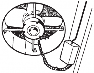
- WIRING THE MOTOR/UNIT:CAUTION: This unit will operate for 1-2 minutes immediately after the power is connected to provide confirmation that the fan is functioning properly.DANGER: The electrical installation and wiring of this fan must be done by a qualified electrician in accordance with all local codes and standards, including fire-rated construction. Failure to do the installation properly can result in fire or even death.NOTE: A few hours of operation without apparent problems does not necessarily imply that the installation is safe.DANGER: Do not use this fan with any solid state speed control device. Use of a solid state speed control can result in a fire causing injury or death.DANGER: Make sure the circuit breaker powering the circuit on which the fan will operate is turned OFF before wiring the motor. You can be shocked or electrocuted if the breaker is not off.Wire the motor directly to the homes power supply in accordance with local building codes and standards.The built in smart sensor alleviates the need for an external thermostat/humidistat that is common on other fans. Instead, use a standard junction box (not included) for electrical safety. The motor is provided with a 1/2″ coupling to secure the conduit to a grounded junction box. Ensure that the junction box is grounded.Do not connect this product to an existing thermostat. The product self regulates according to temperature and humidity so an in-line thermostat is not required.
- THERMOSTAT OPERATION:The integral thermostat/ humidistat operates automatically. When the power ventilator is powered, the fan should start automatically when the attic condition rises above 90°F or 65% relative humidity and will cut off when the attic drops below that setting.DANGER:Switch the power off at the service panel and lock the service panel before servicing the motor. When the service disconnecting means cannot be locked, securely fasten a prominent warning device, such as a tag, to the service panel. This fan is thermostatically controlled – it may start at any time if the power is not switched off at the service panel. Contact with the fan blades while the fan is operating can result in serious injury.
LIMITED LIFETIME WARRANTY
The High Efficiency Powered Attic Fan has a limited lifetime warranty from date of purchase against defects in workmanship and materials. This warranty covers fan blade, motor, thermostat and housing. If you believe any part is defective, call (800) 247- 8368 for Customer Service. If it’s determined that parts need to be returned, they must be shipped freight prepaid to Air Vent, 4117 Pinnacle Point Drive, Suite 400, Dallas, TX 75211. If found to be defective following examination by Air Vent, any defective part will be replaced free of charge and returned freight prepaid. This warranty does not cover any labor costs, including those required for field repair, replacement or removal of any allegedly defective part. This warranty gives you specific legal rights and you may also have other rights which vary from state to state.
REPLACEMENT PLUS PROTECTION
The Air Vent product to which this warranty applies is covered by Replacement Plus protection for a period of five (5) years, provided that the product has been installed in strict accordance with Air Vent’s written installation instructions and in accordance with all local codes and standards, including those pertaining to fire-rated construction. Under this warranty feature, Air Vent, at no charge, will replace any part covered by this warranty and found to be defective during the Replacement Plus period (the Replacement Plus period begins when the power vent installation is completed.) Air Vent’s maximum liability under Replacement Plus will be equal to the reasonable cost of the replacement part, including labor to remove the defective part and install the replacement part.In instances in which Air Vent, according to the terms of this warranty, has agreed to pay the cost of labor required to replace a defective part, Air Vent will provide reimbursement only upon receipt of a copy of the contractor’s invoice or other written evidence of the completion of the work which Air Vent, at its sole discretion, deems acceptable.
 [email protected] | www.airvent.com | 800-AIR-VENT (247-8368)4117 Pinnacle Point Drive | Suite 400 | Dallas, TX 75211
References
[xyz-ips snippet=”download-snippet”]