
![]()
LakeSeries™ Aeration SystemsLS40 & LS60
Owner’s Manual
OWNER’S MANUAL FOR:
LakeSeries Aeration SystemsLS40 & LS60MAX DEPTH 50′

THANK YOU FOR CHOOSING The Airmax® Aeration System

Watch & Learn | How-To Install Videoairmaxeco.com/AirmaxAerationInstallation
Important Safety Instructions
- Read all operating instructions carefully.
- To reduce the risk of electric shock, connect only to a properly grounded, grounding-type receptacle. If in doubt, have the outlet checked by a qualified electrician.
- This unit is to be used in a circuit protected by a ground fault circuit interrupter (GFCI).
- Disconnect unit from power source before handling or maintenance.
- Repair or exchange of cable/power cord must be carried through by the supplier/ manufacturer.
- This unit has not been investigated for use in swimming pool areas.
CAUTION
- Never connect to an extension cord. This may result in equipment failure.

- Do not allow anything to rest on the power cord.
- Do not place the cabinet where people may step on the power cord.
- Never override or “cheat” electrical or mechanical interlock devices.
- Never attempt any maintenance function that is not specified in the user manual.
- Never operate the system if unusual noises or odors are detected. Disconnect the power cord from the outlet and call for service.
- This appliance is not intended for use by persons (including children) with reduced physical, sensory, or mental capabilities, or lack of experience and knowledge, unless they have been given supervision or instruction concerning the use of the appliance by a person responsible for their safety.
- Children should be supervised to ensure that they do not play with the appliance.
- The appliance is to be supplied through a residual current device (RCD) having a rated residual operating current not exceeding 30 mA.
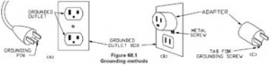
![]() GROUNDING INSTRUCTIONS - This product must be grounded. In the event of an electrical short circuit, grounding reduces the risk of electric shock by providing an escape wire for the electric current. This product is equipped with a cord having a grounding wire with an appropriate grounding plug. The plug must be plugged into an outlet that is properly installed and grounded in accordance with all local codes and ordinances.
GROUNDING INSTRUCTIONS - This product must be grounded. In the event of an electrical short circuit, grounding reduces the risk of electric shock by providing an escape wire for the electric current. This product is equipped with a cord having a grounding wire with an appropriate grounding plug. The plug must be plugged into an outlet that is properly installed and grounded in accordance with all local codes and ordinances.
![]() WARNING - Improper installation of the grounding plug is able to result in a risk of electric shock. When repair or replacement of the cord or plug is required, do not connect the grounding wire to either flat blade terminal. The wire with insulation having an outer surface that is green with or without yellow stripes is the grounding wire.
WARNING - Improper installation of the grounding plug is able to result in a risk of electric shock. When repair or replacement of the cord or plug is required, do not connect the grounding wire to either flat blade terminal. The wire with insulation having an outer surface that is green with or without yellow stripes is the grounding wire.
Check with a qualified electrician or serviceman when the grounding instructions are not completely understood, or when in doubt as to whether the product is properly grounded. Do not modify the plug provided; if it does not fit the outlet, have the proper outlet installed by a qualified technician.
For 120 VAC products: This product is for use on a nominal 120V circuit, and has a grounding plug similar to the plug illustrated in sketch A in Figure below. A temporary adapter similar to the adapter illustrated in sketches B and C may be used to connect this plug to a 2-pole receptacle as shown in sketch B when a properly grounded outlet is not available. The temporary adapter shall be used only until a properly grounded outlet (sketch A) is installed by a qualified electrician. The green colored rigid ear, lug, or similar part extending from the adapter must be connected to a permanent ground such as a properly grounded outlet box cover. Whenever the adapter is used, it must be held in place by a metal screw.
For 230 VAC products: This product is for use on a circuit having a nominal rating more than 120 V and is factory-equipped with a specific electric cord and plug for connection to a proper electric circuit. Only connect the product to an outlet having the same configuration as the plug. Do not use an adapter with this product. When the product must be reconnected for use on a different type of electric circuit, the reconnection shall be made by qualified service personnel.
2
1. System Components
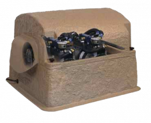
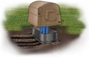
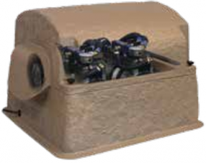
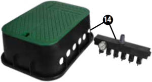
Airmax Composite Cabinet
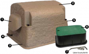
- Enhanced Cooling System tunnels air flow evenly through the cabinet with a high flow cooling fan
- Composite cabinet with removable top protects components while providing easy access
- Elevated base protects against damaging flood water
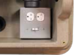
- Pre-wired electrical box simplifies electrical connections for easy setup
- Dual Air Filters - High density cabinet intake pre-filter and compressor air filter maximize the life of the system
- Under-Cabinet Junction Box Allows for easy access to airline connections under the cabinet
- Cabinet Security Bolt Kit protects your investment from unwanted guests
Cabinet Size: 27″L x 24″W x 18.75″H
SilentAir™ RP Series Rocking Piston Compressor
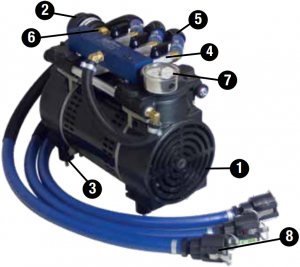
SilentAir with SmartStart™ Technology
Note: LS40 & LS60 Systems Include Two RP Series Rocking Piston Compressors
SmartStart Technology: Protects compressor during pressurized restarts following power supply interruptions.
- High efficiency, continuous-duty rocking piston compressor
- Air Filter maximizes the life of the compressor
- Rubber compressor mounts reduce noise and vibration for silent operation
- Airflow manifold simplifies airflow management to individual diffusers
- Heat-resistant ½″ flex-tube protects against high temperatures of the compressor and braided hose sleeve protects against wear
- Pressure relief valve safeguards from back pressure
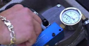
- Pressure gauge helps monitor system performance
- Cam-lock quick disconnects create quick and secure connections
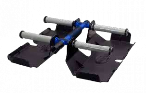
ProAir™ 4 Weighted Diffuser
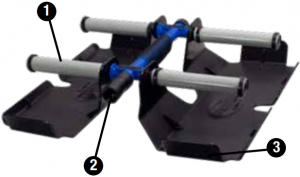
- PTFE non-stick 6″ membrane diffuser sticks provides the synergy of air stones while being virtually maintenance-free
- Check valve prevents back pressure to compressor
- Weighted design keeps diffuser submerged while maintaining an upright position during installation
Diffuser Size: 19″L x 19″W x 5″H
EasySet™ AIRLINE
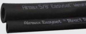
- Self-Weighted Airline: 5/8″ 100′ Roll (#510119): Lead-free weighted airline is made of durable PVC composite. Fish hook resistant and kink-free. Use from pond’s edge to diffuser.
- Direct Burial Airline: 5/8″ 100′ Roll (#510120) Flexible, yet kink-free. Bury from cabinet and compressor to pond’s edge when placing the cabinet and compressor away from the pond.
*Depending on the type of installation, additional connector kits may be required. See section 6 for connector kits.
4
2. System Installation
| Tech Specs: | HP | Running Amps | Volts | Max CFM | Power Cord | Max Pond Size | Max Depth | # Diffusers |
| LS40 | ½ (x2) | 8.2 or 4.1 | 115V or 230V | 9.4 | 6′ | 5 Acres | 50′ | 4 |
| LS60 | ¾ (x2) | 10.6 or 5.3 | 115V or 230V | 11.6 | 6′ | 6+ Acres* | 50′ | 6 |
*Ponds greater than 6 acres require multiple systems
Tools Required:
• Placement Rope • Utility razor knife• Level • Boat/Raft/Swimsuit• Small stone or gravel • Shovel• Rake • Flathead screwdriver• Permanent Marker • Coast Guard-approved life jacket
See Video Instructions of the Airmax Aeration System installation online atairmaxeco.com/LakeSeriesAeration
STEP ONE: Select a Location for the Aeration Cabinet
- Locate cabinet on a solid surface with adequate strength for the weight of the unit.
- Locate cabinet away from irrigation sprinklers.
- Cabinet must always remain above the high water mark.
* Attention: For airline that runs longer than 100′, connector kits are required (sold separately). See Replacement Parts.
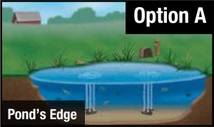
If a power source is available near the pond’s shore, locate the cabinet at the pond’s edge for quicker installation.
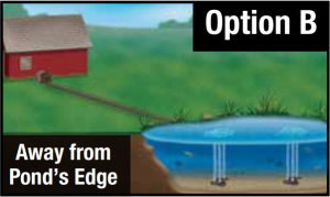
If a power source is not available near the pond’s shore or you would prefer to install the cabinet in another location, install Direct Burial Airline(s) (sold separately) from the cabinet’s location to the pond’s edge
Option B with Remote Manifold
Use a single airline from cabinet to shoreline with valves at pond’s edge.
Learn about installing an optional Remote Manifold Kit online at airmaxeco.com/RemoteManifold
STEP TWO: Prepare the Ground Surface and Place the Cabinet
 1. Place the cabinet on the ground in the selected location and mark an area 6″ wider than the base of the cabinet on all sides.

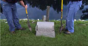
2. Move the cabinet and remove the sod from the area. Then dig a hole approximately 13″ x 18″ x 6″ for the junction box.
5
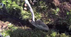
STEP THREE: Excavate Trench and Place Airline(s)
 1. Using your shovel, dig a trench from the cabinet to the pond’s edge. This trench should be a minimum depth of 8″ to protect the airline. We recommend having utility lines marked before you begin digging.
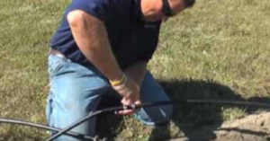
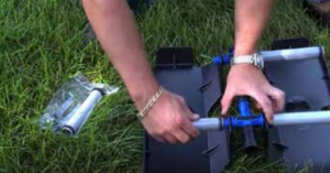
2. Place airline into the trench from the aeration cabinet to the pond’s edge.Option A:Use EasySet weighted airline. There must be a separate run of airline for each diffuser that will be installed. Leave remaining airline coiled at the pond’s edge.Option B:Use Direct Burial airline. There must be a separate run of airline for each diffuser that will be installed. Join multiple sections of direct burial airline using 5/8″ connector kits. First, slide two hose clamps onto one section of airline. Next insert the 5/8″ insert adaptor half way into one section of airline and then insert into next the section of airline. Using a flathead screw driver, secure one of the hose clamps onto each half of the insert adaptor (see image on the left).Option B with Remote Manifold:Use 1″ Direct Burial Airline or PVC Pipe. Only 1 run of airline is required from the cabinet location to the pond’s edge. See Remote Manifold Kit Manual or watch the installation video at airmaxeco.com/RemoteManifold for more information.
STEP FOUR: Connect Airline(s) to the Compressor Manifold
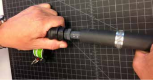
Option A & B:Insert a male adaptor into the weighted airline and secure with a hose clamp. Then attach a male Cam-lock end. Repeat for each diffuser line. (see image on the left)
Next, place the junction box into the hole over top of the airline ends. Then join each line to the female locking end of the Cam-lock from under the cabinet*. Place the cabinet over the junction box. Open the aeration cabinet by unscrewing the 4 lobed thumb bolts. Gently lift the cabinet top and lay on its side next to the base. Use your level to make sure the cabinet is sitting secure and level.
Option B with Remote Manifold:Refer to the Remote Manifold Kit Manual or watch the installation video at airmaxeco.com/RemoteManifold for more information.
Note: You may choose to fill in with small stone or gravel under the cabinet and in the junction box. This allows for a firm base for the cabinet and for drainage.
STEP FIVE: Partially Backfill Airline Trench
Backfill the airline trench in a few areas to temporarily keep the airline in place until installation is complete.
6
STEP SIX: Connect Weighted Airline for Diffusers

Unroll the EasySet weighted airline and remove any kinks or twists. Join enough sections of weighted airline, using 5/8″ connector kits, so that the airline can rest on the bottom of the pond, from the pond’s edge out to the planned location for each diffuser. For option B installations, connect the weighted airline to the direct burial airline or Remote Manifold Kit at the pond’s edge.
Note: Diffusers should be placed equally apart or in areas of low water movement for optimum performance. If you need help choosing the correct location for your diffusers, please contact Airmax or your local dealer.
STEP SEVEN: Connect ProAir Diffusers
See the ProAir Diffuser Manual for assembling and connecting the diffusers.
STEP EIGHT: Start the Aeration System
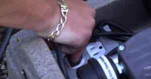
Plug the compressors into the power control outlet inside of the cabinet. Ensure the power switch is in the”ON” position. Plug the power control outlet into a GFCI power outlet.
STEP NINE: Install the ProAir Diffusers
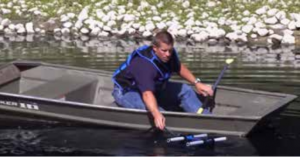
Installing Diffusers from a Boat/Raft: Have one person on shore guiding the airline as a second person uses a boat or raft, extend the airline out to the area of the pond that the diffuser will be located. Gently release the diffuser into the water. Repeat until all diffusers are in position.
7
STEP TEN: Adjust Airflow
Bubbles should be noticeable on the pond’s surface from the diffuser locations. When more than one diffuser is installed, adjust the airflow valves on the compressor manifold (For Option B with Remote Manifold, do this step at the remote manifold). Once an adjustment is made you may need to wait several minutes to see the results at the diffuser location(s).Note: Deeper placement of diffusers and longer runs of airline will require more flow.

STEP ELEVEN: Mark Pressure Gauge
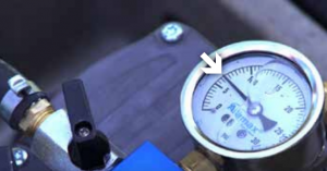
Using a permanent marker, mark the current pressure gauge reading. During regular maintenance if the reading is above or below this mark, it may indicate that the system requires maintenance.
STEP TWELVE: Secure Cabinet & Prepare for Start-Up
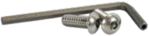
Secure the aeration cabinet lid with the 4 lobed screws. You can also secure the cabinet to prevent unwanted guests with the included Cabinet Security Bolt Kit. Simply replace 2 lobed screws with 2 locking bolts and use the locking bolt tool to secure into place. Complete backfill on airline trenches and level with a rake. Complete installation by reviewing and following the Initial Start-Up Procedure in Section 3.

3. Initial Start-Up & Seasonal Operation
![]() The circulation of poor quality, low oxygen, deep water to the pond’s surface can introduce harmful gases and by-products into the previously healthy upper regions of the water column. These by-products can make the upper regions unfit for aquatic life and could result in fish-kill.
The circulation of poor quality, low oxygen, deep water to the pond’s surface can introduce harmful gases and by-products into the previously healthy upper regions of the water column. These by-products can make the upper regions unfit for aquatic life and could result in fish-kill.
Initial Start-Up Procedure To Prevent Fish-Kill:Follow this procedure anytime system has been shut-off for an extended period of time.
Day 1: Run system for 30 minutes; turn system off for remainder of day.Day 2: Run system for 1 hour; turn system off for remainder of day.Day 3: Run system for 2 hours; turn system off for remainder of day.Day 4: Run system for 4 hours; turn system off for remainder of day.Day 5: Run system for 8 hours; turn system off for remainder of day.Day 6: Run system for 16 hours; turn system off for remainder of day.Day 7: Begin running system 24 hours/day, 7 days/week.
Summer OperationTo reduce the risk of fish kills in hot summer months and for optimum aeration benefits, Airmax Aeration Systems should run continuously throughout the summer.
To enhance pond health, reduce mucky bottoms and enhance pond’s aesthetic appeal, Airmax products:
![]() MuckAway™
MuckAway™ ![]() PondClear™
PondClear™ ![]() EcoBoost™
EcoBoost™ ![]() Pond Dye
Pond Dye
Winter OperationOwner assumes all responsibility for operating Airmax Aeration System during winter months. Operating in freezing conditions on an ice-covered pond will cause large open water areas at diffuser sites. Ice thickness around open areas will be much thinner than the surrounding areas. Airmax strongly recommends that “Danger – Thin Ice” be posted at frequent intervals around pond.
If you choose to turn your system off for the winter, do the following:
- Unplug your aeration system.
- Disconnect compressor flex-tube(s) from airline(s).
- Cover airline ends to prevent debris from entering the airline. We recommend using winterization caps (see replacement parts).
- Move cabinet and compressor inside to keep dry.
- If operating during the winter season, condensation could cause airlines to freeze. If so:• Use 1 cup isopropyl alcohol in the airline running out to each plate.• Turn on compressor to push through line and free any ice blockage.
8
4. Maintenance**
Airmax Aeration Systems are designed for low-maintenance and require minimal scheduled maintenance. Cabinet inlets and outlets should be kept free of debris and weed growth allowing normal ventilation.
- Always unplug system before performing any maintenance or troubleshooting.
- Always unplug system and refer servicing to a qualified electrician when: cord is damaged or frayed, compressor, power control, compressor fan, or other electrical components are producing unusual noises or odors.
- Always use parts that are supplied or approved by Airmax, Inc. Use of other parts may result in poor performance and could create a hazardous situation.**Local environmental conditions may require more frequent maintenance.
WARNING: Compressors are equipped with a thermal overload switch. If temperature becomes high enough to trip the overload, the compressor will shut down. It will then automatically start up when temperature decreases as long as power is applied.
EVERY 3-6 MONTHS - Air Filter: Clean/replace air filter.Cooling Fan: Check to ensure cooling fan is operating. Hot air should be pulled from the cabinet, not blowing in.Pressure Gauge: Mark pressure gauge upon initial start up. Check to verify pressure has not significantly risen above or dropped below initial reading. Normal operation will range between 5-10psi.Pressure Relief Valve: Check to ensure air is not escaping from valve and replace if needed.
EVERY 12-18 MONTHS - Maintenance Kit: It is recommended to install a maintenance kit every 12-18 months to ensure optimum performance.EVERY 24-36 MONTHS - Membrane Sticks: We recommend inspecting and/or cleaning the membrane diffuser sticks every 24-36 months, or anytime the pressure gauge reading is significantly higher than normal or there is a reduction in bubbles from the diffuser. To clean, use Airmax D-Scale (#530298) and a soft cloth.

Watch the Maintenance KitHow-To Video atairmaxeco.com/LakeSeriesAeration
5. Troubleshooting
| IF COMPRESSOR IS NOT OPERATING: | |||
| ISSUE | CHECK | LIKELY CAUSE | CORRECTION |
| Cabinet fan is not running. | Option 1: Check for power. | Compressor and fan are not receiving power. | Open cabinet and ensure the compressor and fan are plugged into the power outlet. Also ensure the power switch is on. |
| Option 2: GFCI circuit tripped. | Damage to electrical cord or low voltage from power supply. | Contact Airmax or local dealer for electrical troubleshooting assistance. | |
| Option 3: GFCI circuit not tripped. | GFCI malfunction. | ||
| Cabinet fan is running. | Option 1: Check compressor for power. | Compressor is not receiving power. | Open cabinet and ensure the compressor is plugged into the power outlet. |
| Option 2: Check compressor capacitor wiring for frays or poor connections. | Wiring loosened or was damaged during shipment or maintenance. | Contact Airmax or local dealer for repair/replacement. | |
| Option 3: No capacitor wiring issues can be seen. | Bad capacitor. | ||
| Option 4: Capacitor has been replaced. | Compressor is bad. | ||
| IF COMPRESSOR IS OPERATING: | |||
| ISSUE | CHECK | LIKELY CAUSE | CORRECTION |
| No bubbles at any diffusers. | Option 1: No air leaks are audible in cabinet. Compressor running louder and possible excessive vibration. | Compressor air filter is dirty/clogged. | Clean or replace air filter. NEVER re-install wet filter. |
| Option 2: Compressor operating normally or making unusual noises. Exhibits reduced pressure and/or air flow. | Compressor needs maintenance kit and possibly new air filter. | Contact Airmax or local dealer with specifications for maintenance kit. Clean or replace air filter. NEVER re-install wet filter. | |
| No bubbles at some diffuser plates. | Option 1: Check for leaks at all connections in line and in cabinet. If none are audible, carefully spray SMALL amount of soapy water onto connections and look for bubbles. | Vibration loosened connection or cracked fitting. | Tighten loose connection or replace cracked fitting as necessary. |
| Option 2: Are all flow control valves in compressor wide open? | Improper “balancing” of diffusers. | Adjust air flow valves on manifold in cabinet until all diffusers operate properly. See Section 2. System Installation for more information. | |
| Option 3: Valves in cabinet are properly “balanced” and no leaks are evident. | Compressor beginning to lose compression and needs maintenance kit. | Contact Airmax or local dealer with compressor specifications for maintenance kit. | |
| Large rolling bubbles instead of fine bubbles at surface above one or more diffuser plates. | Inspect each diffuser plate for malfunction. | Diffuser membrane damaged, diffuser plate fitting broken or diffuser plate is flipped over. | Contact Airmax or local dealer for repair/replacement. |
| Air coming out of pressure relief valve. | Option 1: High pressure reading on gauge. Inspect diffuser plates and tubing for clogging. | Diffuser maintenance needed. | Remove any overgrowth around diffuser membrane surface. See Section 4. Maintenance for more information. |
| Option 2: Low pressure reading on gauge. Diffuser plates not clogged. | Bad pressure relief valve. | Contact Airmax or local dealer for repair/replacement. | |
| Compressor stops working for periods of time, then restarts. | Inspect cooling fan for proper function. | Compressor over-heating due to bad cooling fan. | Contact Airmax or local dealer for fan replacement. If possible, leave top of cabinet open for cooling. Otherwise, unplug system until fan is replaced. |
| Compressor shakes erratically and is making loud noises. | Option 1: Check for low voltage while compressor is running. | Gauge of supply wires to circuit possibly undersized or cabinet is plugged into extension cord. | If gauge of circuit wiring is incorrect, have electrician replace. NEVER use extension cord to operate system for continual use. |
| Option 2: Check for clogged air filter. | Air filter in need of replacement. | Clean or replace air filter. NEVER re-install wet filter. |
9
6. Replacement Parts / Accessories
Optional
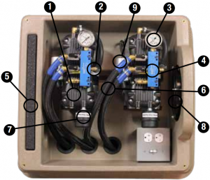
Cabinet & Compressor Replacement Parts
1. RP Series SilentAir High Efficiency Compressor#510501 - RP50 (87R) 1/2 HP Dual Piston Compressor, 115V#510505 - RP50 (87R) 1/2 HP Dual Piston Compressor, 230V#510502 - RP75 (72R) 3/4 HP Dual Piston Compressor, 115V#510506 - RP75 (72R) 3/4 HP Dual Piston Compressor, 230V#510511 - RP50 (87R) 1/2 HP Maintenance Kit#510512 - RP75 (72R) 3/4 HP Maintenance Kit
2. #490239 - Pressure Relief Valve
3. #490272 - Pressure Gauge
4. Airflow Manifold#600237 - LS40#600239 - LS60
5. #510417 - Air Intake Pre-Filter, Large Cabinet
6. #490238 - ½” Flex-Tube Assembly
7. Air Filtera. #510150 - Air Filter, Completeb. #510151 - Air Filter Media Only
8. Cooling Fan#510452 - Cooling Fan for 115V Systems#510453 - Cooling Fan for 230V Systems
9. Capacitor#510407 - RP50 (87R)#510408 - RP75 (72R)
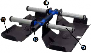
ProAir 4 Replacement Parts
10. #490332 Diffuser Manifold *#490158 1″ Marine Stainless Hose Clamp11. #490337 Diffuser Sled *#490118 ½” to ¾” Insert Reducer Adapter12. #510168 PTFE 6″ Membrane Stick *#490118 3/8″ to ¾” Insert Reducer Adapter13. #490340 Check Valve *Not shown in Diagram
EasySet Airline
#510119 5/8″ Weighted Airline, 100′ Roll#510120 5/8″ Direct Burial Airline, 100′ Roll#490323 Winterization Cap
Optional Remote Manifold Kits
14. #600193 Airmax LS40 4-Port Remote Manifold Kit#600191 Airmax LS60 6-Port Remote Manifold Kit
Connector Kit
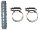
#490206 5/8″ Connector Kit
Security Kits
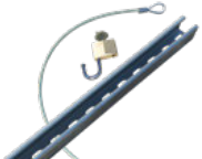
#510430 - Cabinet Security Stake Kit (Optional)#510424 - Cabinet Security Bolt Kit
THANK YOU FOR CHOOSING
![]()
Cleaning Water Naturally™ www.airmaxeco.com
10
NOTES
Visit airmaxeco.com or call your local Airmax Dealer with questions or to order parts.
18
Airmax, Inc.Airmax Aeration SystemsLimited Warranty
Airmax, Inc. warrants to the original purchaser (the end user) of any Airmax Aeration System manufactured by Airmax, Inc. that any aeration system component which proves to be defective in materials or workmanship, as determined by the factory within the timeframe specified below from the shipping date, will be repaired or replaced at no charge with a new or remanufactured part, and returned freight prepaid. The end user shall assume all the responsibility and expense for removal, packaging, and freight to ship to Airmax®, Inc. to determine the warranty claim and for all reinstallation expenses.
• Cabinet Lifetime • Compressor 2 Years • Airline & Diffusers 5 Years
The warranty is void in cases where damage results from: improper installation, improper electrical connection, improper voltage, alteration, lightning, careless handling, misuse, abuse, disassembly of motor or failure to follow maintenance or operating instructions. Modification or repair by an unauthorized repair facility will void the warranty. Compressor seals, piston cups, cylinder sleeves, valves, air filters and diffuser membranes are considered wear parts and are not covered under warranty.
In no case will Airmax, Inc. or its dealers accept responsibility for any costs incurred by the user during installation, removal, inspection, evaluation, repair, parts replacement, or for return freight. Nor will any liability be accepted for loss of use, loss of profits, loss of goodwill, for consequential damage, or for personal injuries to the purchaser or any person.
In the event of problems believed to be covered under warranty, it will be necessary to notify the dealer who will try to help resolve the problem and who may contact the factory for additional assistance. If it is concluded that there may be a defect which may be covered under warranty, it will be necessary to get a Return Material Authorization (RMA) from the dealer before shipment. Freight collect shipments will not be accepted by the factory on warranties or repairs.
The product or part(s) must be returned freight prepaid, to the factory, as directed, and in its original packaging or in a container which will prevent damage. Parts returned under warranty and damaged during shipping will not be covered under warranty for the shipping damage. If the factory evaluation of the returned goods concludes that the failure is due to defects in materials or workmanship, the part or parts in question will be replaced under warranty with new parts, remanufactured parts, or will be repaired; at the factory’s option. The warranty period for all parts supplied under warranty will terminate at the end of the original product’s warranty. All warranty shipments from the factory will be shipped freight prepaid.
Warranty registration is HIGHLY recommended.
No implied warranties of any kind are made by Airmax, Inc. for its products, and no other warranties, whether expressed or implied, including implied warranties of merchantability and fitness for a particular purpose, shall apply. Should an Airmax, Inc. product prove to be defective in materials or workmanship, the retail purchaser’s sole remedy shall be repair or replacement of the product as expressly provided above.
The manufacturer’s warranty will begin from the dealer’s original purchase date if the product is not registered. To register a product you are required to fill out the warranty form at airmaxeco.com/warranty. Warranty registration must be submitted directly to Airmax within 30 days of the end-users purchase date. When making warranty claims end-users may be required to supply their proof of purchase.
19
Airmax, Inc.
15425 Chets Way StreetArmada, MI 48005
(866) 4-AIRMAXairmaxeco.com
#510472 V2
References
[xyz-ips snippet=”download-snippet”]