
Airrex Infrared Heater AH-200/300/800 User Manual
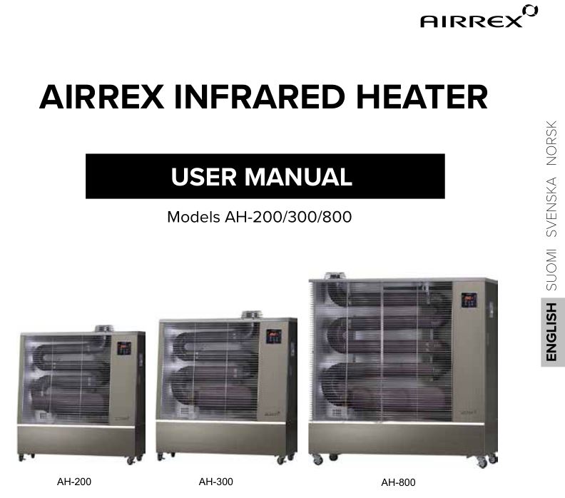
- Thank you for purchasing an Airrex infrared heater!
- Please read the user manual carefully before operating the heater.
- Once you have read the user manual, ensure that it is stored in such a way that it is available to everyone using the heater.
- Study the safety instructions with particular care before using the heater.
- These heaters have been adjusted to function in Northern European conditions. If you take the heater to other areas, check the mains voltage in your country of destination.
- This user manual also includes instructions for activating the three-year warranty.
- Due to active product development, the manufacturer reserves the right to make changes to the technical specifications and functional descriptions in this manual without separate notice.
![]()
SAFETY INSTRUCTIONS
The purpose of these safety instructions is to ensure the safe use of the Airrex heaters. Adherence to these instructions prevents the risk of injury or death and damage to the heating device as well as other items or premises.Please read the safety instructions with care.The instructions feature two concepts: “Warning” and “Note”.
![]()
This marking indicates a risk of injury and/or death.
![]()
T his marking indicates the risk of minor injury or structural damage.
SYMBOLS USED IN THE MANUAL:
![]()
Prohibited measure
![]()
Mandatory measure
![]()
![]() Only use 220/230 V mains electricity. Incorrect voltage may cause a fire or electrical shock.
Only use 220/230 V mains electricity. Incorrect voltage may cause a fire or electrical shock.
![]()
Always ensure the condition of the power cord and avoid bending it or placing anything on the cord. A damaged power cord or plug may cause a short circuit, electric shock or even fire.![]() Do not handle the power cord with wet hands. This may cause a short circuit, fire or risk of death.
Do not handle the power cord with wet hands. This may cause a short circuit, fire or risk of death.
![]() Never use any containers carrying flammable liquids or aerosols near the heater or leave them in its immediate vicinity due to the fire and/or explosion risk they present.
Never use any containers carrying flammable liquids or aerosols near the heater or leave them in its immediate vicinity due to the fire and/or explosion risk they present.
![]() Ensure that the fuse adheres to the recommendation (250 V / 3.15 A). The wrong fuse may cause malfunctions, overheating or a fire.
Ensure that the fuse adheres to the recommendation (250 V / 3.15 A). The wrong fuse may cause malfunctions, overheating or a fire.
![]() Do not deactivate the heater by cutting the power supply or disconnecting the power plug. Cutting power during heating may lead to malfunctions or an electric shock. Always use the power button on the device or the ON/OFF button on the remote control.
Do not deactivate the heater by cutting the power supply or disconnecting the power plug. Cutting power during heating may lead to malfunctions or an electric shock. Always use the power button on the device or the ON/OFF button on the remote control.
![]() Damaged power cords must be replaced immediately at a maintenance shop authorised by the manufacturer or importer or some other maintenance shop authorised for electrical repairs.
Damaged power cords must be replaced immediately at a maintenance shop authorised by the manufacturer or importer or some other maintenance shop authorised for electrical repairs.
![]() If the plug gets dirty, clean it carefully before connecting it to the socket. A dirty plug may cause a short circuit, smoke and/or fire.
If the plug gets dirty, clean it carefully before connecting it to the socket. A dirty plug may cause a short circuit, smoke and/or fire.
![]() Do not extend the power cord by connecting additional lengths of cord to it or its connector plugs. Poorly-made connections may cause a short circuit, electric shock or fire.
Do not extend the power cord by connecting additional lengths of cord to it or its connector plugs. Poorly-made connections may cause a short circuit, electric shock or fire.
![]() Before cleaning and maintaining the device, disconnect the power plug from the socket and allow the device to cool down sufficiently. Neglecting these instructions may lead to burns or an electric shock.
Before cleaning and maintaining the device, disconnect the power plug from the socket and allow the device to cool down sufficiently. Neglecting these instructions may lead to burns or an electric shock.
![]() The power cord of the device may only be connected to a grounded socket.
The power cord of the device may only be connected to a grounded socket.
![]() Do not cover the heater with any obstructions such as clothing, fabric or plastic bags. This may cause a fire.
Do not cover the heater with any obstructions such as clothing, fabric or plastic bags. This may cause a fire.
KEEP THESE INSTRUCTIONS ACCESSIBLE TO ALL USERS NEAR THE DEVICE.
![]() Do not place your hands or any items inside the safety mesh. Touching the internal components of the heater may cause burns or an electric shock.
Do not place your hands or any items inside the safety mesh. Touching the internal components of the heater may cause burns or an electric shock.
![]() Do not move an operating heater. Switch off the heater and unplug the power cord before moving the device.
Do not move an operating heater. Switch off the heater and unplug the power cord before moving the device.
![]() Only use the heater to heat indoor spaces. Do not use it to dry clothing. If the heater is used for heating premises intended for plants or animals, the exhaust gases must be fed outside through a flue, and a sufficient supply of fresh air must be ensured.
Only use the heater to heat indoor spaces. Do not use it to dry clothing. If the heater is used for heating premises intended for plants or animals, the exhaust gases must be fed outside through a flue, and a sufficient supply of fresh air must be ensured.
![]() Do not use the heater in closed spaces or spaces primarily occupied by children, elderly people or disabled people. Always ensure that those in the same space as the heater understand the necessity for efficient ventilation.
Do not use the heater in closed spaces or spaces primarily occupied by children, elderly people or disabled people. Always ensure that those in the same space as the heater understand the necessity for efficient ventilation.
![]() We recommend that this heater not be used at extremely high elevations. Do not use the device more than 1,500 m above sea level. At an elevation of 700–1,500, the ventilation must be efficient. Poor ventilation of the space being heated may lead to the formation of carbon monoxide, which may cause injury or death.
We recommend that this heater not be used at extremely high elevations. Do not use the device more than 1,500 m above sea level. At an elevation of 700–1,500, the ventilation must be efficient. Poor ventilation of the space being heated may lead to the formation of carbon monoxide, which may cause injury or death.
![]() Do not use water to clean the heater. Water may cause a short circuit, electrical shock and/or fire.
Do not use water to clean the heater. Water may cause a short circuit, electrical shock and/or fire.
![]() Do not use petrol, thinner or other technical solvents to clean the heater. They may cause a short circuit, electrical and/or fire.
Do not use petrol, thinner or other technical solvents to clean the heater. They may cause a short circuit, electrical and/or fire.
![]() Do not place any electrical devices or heavy items on the heater. Items on the device may cause malfunctions, electric shocks or injury upon falling off the heater.
Do not place any electrical devices or heavy items on the heater. Items on the device may cause malfunctions, electric shocks or injury upon falling off the heater.
![]() Only use the heater in well-ventilated open spaces where the air is replaced 1–2 times an hour. Using the heater in poorly ventilated spaces may generate carbon monoxide, which can lead to injury or death.
Only use the heater in well-ventilated open spaces where the air is replaced 1–2 times an hour. Using the heater in poorly ventilated spaces may generate carbon monoxide, which can lead to injury or death.
![]() Do not use the device in rooms where people sleep without a flue leading outside the building and without ensuring a sufficient supply of replacement air.
Do not use the device in rooms where people sleep without a flue leading outside the building and without ensuring a sufficient supply of replacement air.
![]() The heater must be placed in a location where the safety distance requirements are met. There must a clearance of 15 cm on all sides of the device and at least 1 m in front of and above the device.
The heater must be placed in a location where the safety distance requirements are met. There must a clearance of 15 cm on all sides of the device and at least 1 m in front of and above the device.
![]()
![]() Do not position the heater on an unstable, inclined or wobbly foundation. The device tilting and/or falling over may cause malfunctions and lead to a fire.
Do not position the heater on an unstable, inclined or wobbly foundation. The device tilting and/or falling over may cause malfunctions and lead to a fire.
![]()
Do not attempt to dismantle the remote control of the heater, and always protect it against strong impacts.
![]()
If the heater will not be used for an extended period of time, unplug the power cord.
![]()
During thunder storms, the device must be switched off and unplugged from the power socket.
![]()
Never allow the heater to get wet; the device must not be used in bathrooms or other similar spaces. Water may cause a short circuit and/or fire.
![]() The heater must be stored in a dry location indoors. Do not store in hot or particularly humid spaces. Possible corrosion caused by humidity may cause malfunctions.
The heater must be stored in a dry location indoors. Do not store in hot or particularly humid spaces. Possible corrosion caused by humidity may cause malfunctions.
IMPORTANT THINGS TO NOTE BEFORE OPERATION
ENSURE THE SAFETY OF THE HEATER’S LOCATION
- The vicinity of the heater must be free of flammable materials.
- There must always be 15 cm of clearance between the sides and back of the heater and the nearest piece of furniture or other obstruction.
- A distance of one (1) metre in front of and above the heater must be kept clear of all items and materials. Please note that different materials may react differently to heat.
- Ensure that there are no fabrics, plastics or other items near the heater that may cover it if they are moved by an air current or other force. The heater being covered by a fabric or other obstruction may cause a fire.
- The heater must be placed on an even base.
- When the heater is in place, lock its casters.
- Separate flue gas discharge piping must be used in small spaces. The diameter of the piping must be 75 mm and the maximum length is 5 metres. Ensure that water cannot flow into the heater through the discharge piping.
- Place extinguishing equipment suitable for oil and chemical fires in the immediate vicinity of the heater.
- Do not place the heater in direct sunlight or near a strong heat source.
- Position the heater in the immediate vicinity of a power socket.
- The power cord plug must always be easily accessible.
USE ONLY HIGH-GRADE BIODIESEL OR LIGHT FUEL OIL IN THE HEATER.
- The use of fuels other than light fuel oil or diesel may cause malfunctions or excessive soot formation.
- ALWAYS switch off the heater when adding fuel to the tank.
- All heater fuel leaks must be repaired immediately at a maintenance shop authorised by the manufacturer/importer.
- When handling fuel, observe all relevant safety instructions.
THE HEATER’S OPERATING VOLTAGE IS 220 / 230 V / 50 HZ
- It is the responsibility of the user to connect the device to a power grid that supplies the appropriate voltage.
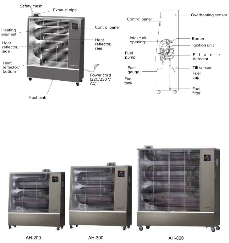
HEATER STRUCTURE
STRUCTURAL FIGURES
OPERATING SWITCHES AND DISPLAY
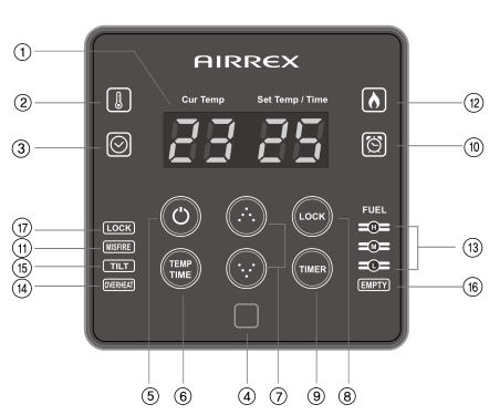
- LED-DISPLAYThe display can be used to check the temperature, timer, error codes, etc.
- THERMOSTAT OPERATIONThis light is on when the heater is in thermostat operation mode.
- TIMER OPERATIONThis light is on when the heater is in timer operation mode.
- REMOTE CONTROL RECEIVER
- POWER BUTTON (ON/OFF)Switches the device power on and off.
- MODE SELECTIONThis button is used to select the desired operating mode between thermostat operation and timer operation.
- ARROW BUTTONS FOR ADJUSTMENT FUNCTIONS (INCREASE/DECREASE)These buttons are used to adjust the desired temperature and set the length of the heating cycle.
- KEY LOCKPressing this button for three (3) seconds locks the keys. Correspondingly, pressing the button for another three (3) seconds unlocks the keys.
- SHUTDOWN TIMERThis button activates or deactivates the shutdown timer function.
- SHUTDOWN TIMER INDICATOR LIGHTThe light indicates whether or not the shutdown timer is active.
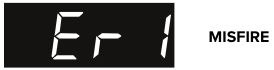
- BURNER FAULT INDICATOR LIGHTThis indicator light is lit if the burner has failed or shut down during operation.
- BURNER INDICATOR LIGHTThis indicator light is on when the burner is active.
- FUEL GAUGEThe column of three lights indicates the remaining fuel.
- OVERHEAT WARNING LIGHTThe warning light is lit if the temperature in the top section of the heating element exceeds 105°C. The heater is switched off.
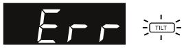
- TILT SENSOR’S WARNING LIGHTThe warning light is lit if the device is tilted by more than 30°C or is subjected to an outside force that results in significant movement.
- FUEL AMOUNT WARNING LIGHTThe warning light is lit when the fuel tank is almost empty.
- KEY LOCK INDICATOR LIGHTWhen this light is lit, the keys of the device are locked, which means that adjustments cannot be made.
REMOTE CONTROL
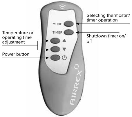
- Aim the end of the remote control towards the heater.
- Strong sunlight or bright neon or fluorescent lights may disrupt the operation of the remote control. If you suspect that the lighting conditions may be causing problems, use the remote control right in front of the heater.
- The remote control emits a sound whenever the heater detects a command.
- If the remote control will not be used for an extended period of time, remove the batteries.
- Protect the remote control against all liquids.
REPLACING THE REMOTE CONTROL BATTERIES
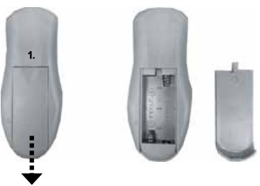
- OPENING THE BATTERY CASEPress area 1 lightly and push the battery case cover in the direction of the arrow.
- REPLACING THE BATTERIESRemove the old batteries and install the new ones. Ensure that you align the batteries correctly.Each battery’s (+) terminal must connect with the corresponding marking in the case.
- CLOSING THE BATTERY CASEPush the battery case into place until you hear the lock click.
BURNER STRUCTURE

OPERATING INSTRUCTIONS
ACTIVATION AND DEACTIVATION
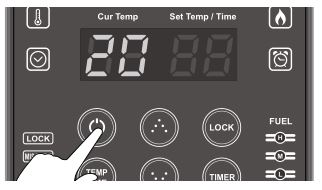
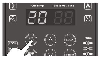
- START THE HEATER
- Press the power button. The device emits an audio signal upon activation.
- The device can be switched off by pressing the same button.

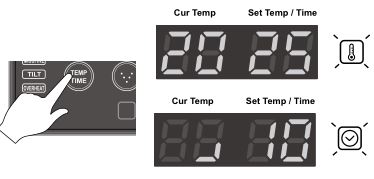
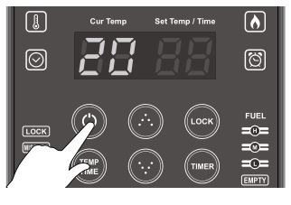
- SELECT THE OPERATING MODE
- Select the desired operating mode, either thermostat or timer operation.
- You can make the selection with the TEMP/TIME button.
- The default is thermostat operation.
- SET THE TARGET TEMPERATURE OR HEATING TIME WITH THE ARROW BUTTONS
- The temperature can be adjusted between 0–40 ºC.
- The minimum heating time is 10 min, and there is no upper limit.NOTE!After activation, the heater’s default operating mode is thermostat operation, which is shown by the corresponding indicator light.
SHUTDOWN TIMERIf you would like the heater to switch off on its own, you can use the shutdown timer.Use the TIMER button to activate the shutdown function. Then select the desired shutdown delay with the arrow buttons. The minimum delay is 30 minutes. 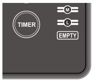
TIPS FOR USING THE HEATER
- The heater is activated when the adjusted temperature is 2°C higher than the ambient temperature.
- After activation, the heater defaults to thermostat operation.
- When the device is deactivated, all timer functions are reset and must be set again if they are needed.
THERMOSTAT OPERATION
In this mode, you can set the desired temperature, after which the heater operates automatically and switches itself on as needed to maintain the set temperature. Thermostat operation is selected by default when the heater is activated.
- Plug in the power cord. Start the heater. When the heater is in operation, the current temperature is shown on the left and the set target temperature is shown on the right.
- The corresponding signal light is on when thermostat operation is selected. To switch from thermostat operation to timer operation, press the TEMP/TIME button.
- The temperature can be adjusted with the arrow buttons.
- The temperature can be adjusted within the range 0–40ºC
- The heater’s default setting is 25ºC.
- Pressing an arrow button for two (2) seconds continuously will change the temperature setting faster.
- The range of the current temperature display is -9…+50ºC.
- When powered on, the heater is activated automatically when the current temperature drops by two (2ºC) degrees below the target temperature. Correspondingly, the heater is deactivated when the current temperature rises by one degree (1ºC) above the set target temperature.
- When you press the power button to switch off the device, the display only shows the current temperature.


TIPS FOR USING THE HEATER
- If the current temperature is -9ºC, the text “LO” appears in the current temperature view. If the current temperature is +50ºC, the text “HI” appears in the current temperature view.
- A single press of an arrow button changes the temperature settings by one degree. Pressing an arrow button for more than two (2) seconds changes the display setting by one digit per 0.2 seconds.
- Pressing both arrow buttons for five (5) seconds changes the temperature unit from Celsius (ºC) to Fahrenheit (ºF). The device uses Celsius degrees (ºC) by default.
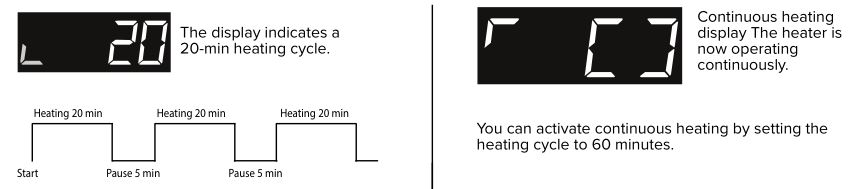
TIMER OPERATION
Timer operation can be used to operate the heater in intervals. The operating time can be set between 10 and 55 minutes. The pause between cycles is always five minutes. The heater can also be set to be continuously on. In timer operation, the heater does not take the thermostat’s temperature or the set temperature into account.
- START THE HEATER
- SELECT TIMER OPERATIONSelect timer operation by pressing the TEMP/TIME button. The timer operation signal light is lit.
- When timer operation is on, a light ring is shown on the left. The set operating time (in minutes) is displayed on the right. Select the desired operating time with the arrow buttons. The selected time flashes on the display. If the arrow buttons are not pressed for three (3) seconds, the time setting shown on screen is activated.
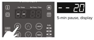
- The operating time can be set between 10 and 55 minutes, or the heater can be set to run continuously. Once the operating cycle ends, the heater always suspends operation for five (5) minutes. Two lines (- -) are shown on the display alongside the operating time to indicate the pause.


CLEANING AND MAINTENANCE
CLEANING SURFACES
OBSERVE THE FOLLOWING CLEANING INSTRUCTIONS:
- External surfaces can be cleaned lightly with mild cleaning agents, if necessary.
- Clean the reflectors behind and to the sides of the heating pipes with a soft and clean (microfibre) cloth.
NOTE!The heating pipes are coated with a ceramic layer. Clean them with special care. Do not use any abrasive cleaning agents.
DO NOT DETACH OR REMOVE ANY HEATING PIPES!
- Clean the key panel and LED display with a soft and clean (microfibre) cloth.
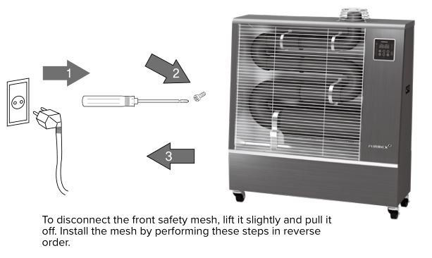
- Reinstall the safety mesh after cleaning.
HEATER STORAGE
It is a good idea to unplug the power cord for every period of storage. Place the power cord in the tank inside the heater to ensure that it is not caught under a tyre, for example, when being moved.
Allow the heater to cool down completely before placing it in storage. Protect the heater during storage by covering it with the bag included in the delivery.
If the heater will be out of use for an extended period, fill the fuel tank with an additive to prevent any microbial growth inside the tank.
![]()
Storing the heater outdoors or in an extremely humid environment may cause corrosion resulting in significant technical damage.
REPLACING THE FUEL FILTER
The fuel filter is located in the heater tank. We recommend replacing the fuel filter regularly, but at least once per heating season.
REPLACING THE FUEL FILTER
- Disconnect the fuel hoses from the fuel pump.
- Lift off the rubber seal on the fuel tank with a screwdriver.
- Unscrew the nut lightly with a spanner.
- Ensure that two (2) small O-rings remain on the copper pipe before installing the new fuel filter.
- Screw the fuel filter lightly onto the copper pipe.
- Place the fuel filter back into the tank and attach the fuel hoses to the fuel pump.
NOTE!The fuel system may require bleeding after fuel filter replacement.
BLEEDING THE FUEL SYSTEM
If the heater’s fuel pump sounds exceptionally loud and the heater does not run properly, the probable cause is air in the fuel system.
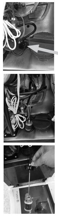
BLEEDING THE FUEL SYSTEM
- Loosen the bleeder wing nut at the bottom of the fuel pump by 2–3 rotations.
- Start the heater.
- When you hear the fuel pump start, wait for 2–3 seconds and close the bleed screw.
Bleeding the system may require this procedure to be repeated 2–3 times.
DIAGNOSING AND REPAIRING MALFUNCTIONS
ERROR MESSAGES
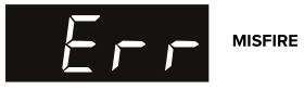
- MALFUNCTIONBurner malfunction.
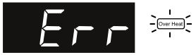
- OVERHEATThe warning light is lit when the temperature in the top section of the heating element exceeds 105°C. The heater is deactivated by its safety systems. Once the device has cooled down, it is automatically restarted.
- SHOCK OR TILTThe warning light is lit if the device is tilted by more than 30°C or subjected to a strong shock or jolt. The heater is deactivated by its safety systems.
- FUEL TANK EMPTYWhen the fuel tank is entirely empty, the message “OIL” appears on the display. In addition to this, the fuel gauge’s EMPTY indicator light is continuously on and the device lets out a continuous audio signal. The tank cannot be emptied enough to require the fuel pump to be bled.
- SAFETY SYSTEM ERRORThe safety system shuts down all burner functions. Please contact an authorised maintenance service.
- SAFETY SYSTEM ERRORThe safety systems shuts down all burner functions. Please contact an authorised maintenance service.

NOTE!If the heater is shut down by the safety systems, carefully ventilate the space being heated to clear all exhaust gases and/or fuel vapours.
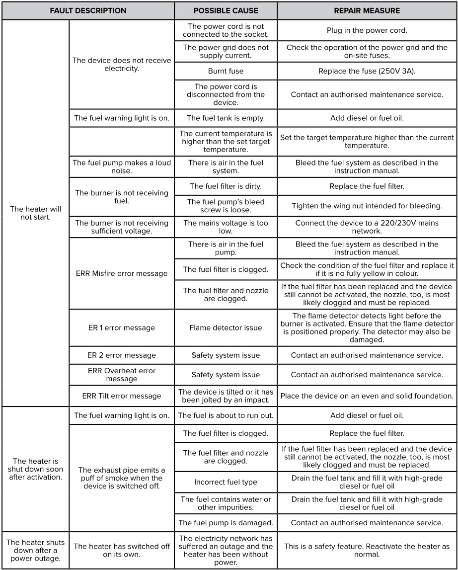
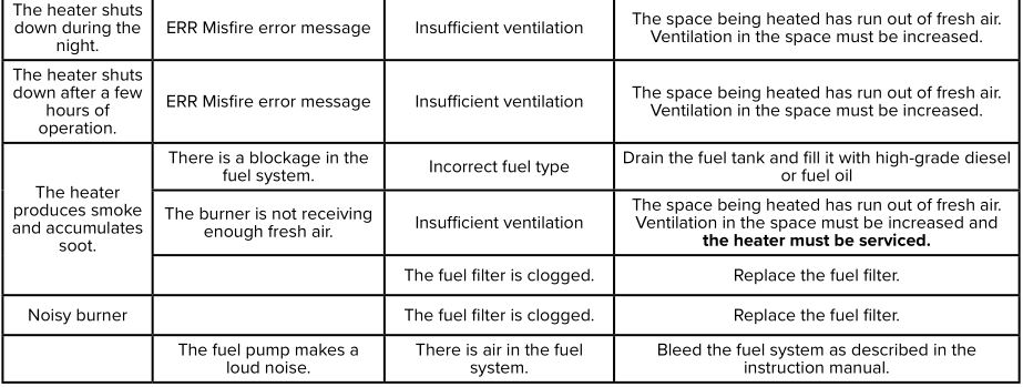
TIP FOR USING THE HEATERSee all possible causes of error messages in the table on page 16.
DIAGNOSING AND REPAIRING OPERATING FAILURES
![]()
ENSURE SUFFICIENT VENTILATION!
More than 85% of all operating malfunctions are due to insufficient ventilation. It is advisable to place the heater in a central and open location so that it can radiate heat in front of it without obstruction. The heater needs oxygen to run, which is why sufficient ventilation in the room must be ensured. Natural ventilation in accordance with the applicable building regulations is sufficient, provided that no inlet or outlet vents have been blocked. It is also not recommended to position a replacement air vent near the device so that the thermostat control is not disturbed.

- It is important to ensure that air circulates in the space being heated. Ideally, air should be fed in through an inlet vent at the bottom and the CO2-containing air should discharged through an outlet vent at the top.
- The recommended diameter of the ventilation openings is 75–100 mm.
- If the room has an inlet or outlet vent only, air cannot circulate in it and the ventilation is insufficient. The situation is the same if ventilation is only provided through an open window.
- Air flowing in from slightly opened doors/windows does not guarantee sufficient ventilation.
- The heater requires sufficient ventilation even when the exhaust pipe is led out of the room being heated.
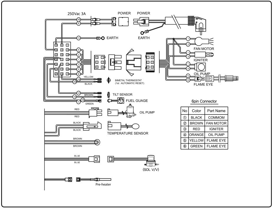
TECHNICAL SPECIFICATIONS AND CONNECTION DIAGRAM
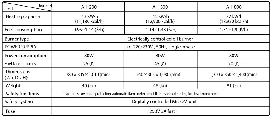
- The manufacturer does not recommend these heaters be used in temperatures under -20ºC.
- Due to active product development, the manufacturer reserves the right to make changes to the technical specifications and functional descriptions in this manual without separate notice.
- The device may only be connected to a 220/230 V electricity network.
AIRREX WARRANTY
The more the Airrex heaters are used, the more reliable their operation is. Airrex utilises strict quality control processes. Each product is inspected after completion, and some products are subjected to unrelenting functional tests.
To resolve any unexpected faults or malfunctions, please contact your retailer or importer.If the fault or malfunction is caused by a defect in the product or one of its components, the product will be replaced free of charge during the warranty period, provided that the following conditions are met:
NORMAL WARRANTY
- The warranty period is 12 months from the device’s date of purchase.
- If the fault or malfunction is caused by user error or damage caused to the device by an external factor, all repair costs are charged to the customer.
- Warranty maintenance or repairs require the original purchase receipt to verify the date of purchase.
- The validity of the warranty requires the device to have been purchased from an official retailer authorised by the importer.
- All costs connected to transporting the device to warranty servicing or warranty repair are at the customer’s expense. Keep the original packaging to facilitate any transport. The retailer/importer will cover the costs connected to returning the device to the customer after warranty servicing or warranty repair (if the device was approved for warranty servicing/repair).
3-YEAR ADDITIONAL WARRANTY
The importer of Airrex infrared heaters Rex Nordic Oy grants a 3-year warranty for imported diesel infrared heaters. One of the prerequisites for a 3-year warranty is that you activate the warranty within 4 weeks of the date of purchase. The guarantee must be activated electronically at: www.rexnordic.com.
3-YEAR WARRANTY TERMS
- The warranty covers all parts that are covered by the general warranty terms.
- The warranty only covers products imported by Rex Nordic Group and sold by an official dealer thereof.
- Only dealers authorised by Rex Nordic Group are allowed to market and advertise the 3-year warranty.
- Print the warranty certificate on the extended warranty and retain it as an attachment to the purchase receipt.
- If the device is sent to warranty servicing within the extended warranty period, the receipt and warranty certificate for the extended warranty must be sent with it.
- If the fault or malfunction is caused by user error or damage caused to the device by an external factor, all repair costs are charged to the customer.
- Warranty servicing or warranty repair require the receipt and warranty certificate for the extended warranty.
- All costs connected to transporting the device to warranty servicing or warranty repair are at the customer’s expense. Keep the original packaging to facilitate any transport.
- The costs connected to returning the device to the customer after warranty servicing or warranty repair (if the device was approved for warranty servicing/repair) are at the expense of the dealer/importer.
VALIDITY OF THE 3-YEAR WARRANTY
The warranty will remain valid for three years starting from the date of purchase indicated in the receipt, provided that the warranty is activated according to the instructions above. The 3-year warranty is only valid with the original receipt. Remember to keep the receipt. It is proof of a valid warranty.
![]()
MANUFACTURER
HEPHZIBAH CO., LTD(Juan-dong) 86, Gilpa-ro71beon-gil, Nam-gu,Incheon, Korea+82 32 509 5834
IMPORTER
REX NORDIC GROUPMustanlähteentie 24 A07230 AskolaFINLAND
FINLAND +358 40 180 11 11SWEDEN +46 72 200 22 22NORWAY +47 4000 66 16INTERNATIONAL +358 40 180 11 11
[email protected]www.rexnordic.com
Airrex Infrared Heater AH-200/300/800 User Manual – Airrex Infrared Heater AH-200/300/800 User Manual –
[xyz-ips snippet=”download-snippet”]