AJAX WallSwitch – Wireless Power Relay with Energy Monitor User Manual
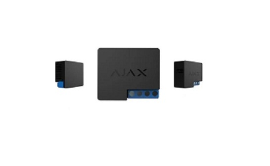
Functional Elements
- Antenna
- Power supply terminal block
- Contacts terminal block
- Function button
- Light indicator
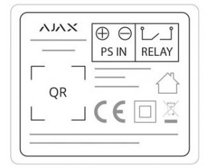
- PS IN Terminals – “+” and “-” contact terminals, 7-24 V DC input power supply.
- Relay Terminals – output potential-free terminals.

Operating Principle
![]() Do not connect Relay power supply input terminals exceeding 36V or alternate current sources. It creates a risk or fire and will damage the device!
Do not connect Relay power supply input terminals exceeding 36V or alternate current sources. It creates a risk or fire and will damage the device!
Regardless of the type of electrical circuit, only a qualified electrician should install Relay!Relay is powered by a 724 V DC source. The recommended voltage values are 12 V, and 24 V. Use the Ajax Security System app to connect and set up Relay.Relay features dry (potential-free) contacts. The contacts are not connected to the device galvanically so that Relay can imitate a button, switch, etc. in electrical circuits of various voltages (sirens, electrical valves, electromagnetic locks). The miniature body makes it possible to install Relay inside a junction box, switchboard, or a switch.Relay closes and opens the contacts by user command from the app or automatically by scenario.
Relay Operation Modes:
- Bistable: Relay opens or closes contact and remains in this state.
- Pulse: Relay opens or closes contacts for a pre-set time (from 0.5 to 255 seconds) then switches back to the initial state.
Connecting to the Hub
Before Connecting the Device:
- Switch on the hub and check its Internet connection (the logo glows white or green).
- Install the Ajax app. Create the account, add the hub to the app, and create at least one room.
- Make sure that the hub is not armed, and it does not update by checking its status in the Ajax app.
- Connect Relay to 12 or 24 V power supply.
![]() Only users with administrator rights can add a device to the app.
Only users with administrator rights can add a device to the app.
To Pair Relay with a Hub:
- Click Add device in the Ajax app.
- Name the device, scan it, or enter the QR Code manually (located on the case and packaging), select the room.
- Click Add — the countdown will begin.
- Press the functional button.
For detection and pairing to occur, the device should be located in the coverage area of the hub’s wireless network (at the same object). The connection request is transmitted only at the moment of switching on the device.If the device failed to pair, wait 30 seconds and then retry. Relay will appear in the list of hub devices.The device statuses update depends on the ping interval set in the hub settings. The default value is 36 seconds.
![]() When switching on for the first time, Relay contacts are open! When deleting Relay from the system, contacts open!
When switching on for the first time, Relay contacts are open! When deleting Relay from the system, contacts open!
States
- Devices
- Relay
|
Parameter |
Value |
| Jeweller Signal Strength | Signal strength between the hub and Relay |
| Connection | Connection status between the hub and the relay |
| Routed Through ReX | Displays the status of using the ReX range extender |
| Active | State of the relay contacts (closed / open) |
| Voltage | The current input voltage |
| Temporary Deactivation | Displays the status of the device: active or completely disabled by the user |
| Firmware | Device firmware version |
| Device ID | Device identifier |
Settings
- Devices
- Relay
- Settings

| First field | Device name, can be edited |
| Room | Selecting the virtual room to which the device is assigned |
| Relay Mode | Choosing the relay operation mode
|
| Contact State | Normal contact state
|
| Pulse duration, sec | Selecting the pulse duration in the pulse mode: From 0.5 to 255 seconds |
| Scenarios | Opens the menu for creating and configuring scenarios |
| Jeweller Signal Strength Test | Switches the relay to the signal strength test mode |
| User Guide | Opens the Relay User Manual |
| Temporary Deactivation | Allows a user to deactivate the device without removing it from the system. The device will not execute system commands and participate in automation scenarios. All notifications and alarms will be ignored
Please note that deactivated device will save its current state (active or inactive) |
| Unpair Device | Disconnect Relay from a hub and delete its settings |
Voltage Protection — The contact will open when the voltage exceeds the limits of 6.536.5 V.Temperature Protection — The contact will be opened when the temperature threshold of 85° inside Relay is reached.
Indication
The Relay light indicator can light green depending on the device status.When not paired with the hub, the light indicator blinks periodically. When the functional button is pressed, the light indicator lights up.
Functionality Testing
The Ajax security system allows conducting tests for checking the functionality of connected devices.The tests do not start immediately but within a period of 36 seconds when using default settings. The test time start depends on the settings of the detector ping interval (the Jeweller menu in the hub settings).Jeweller Signal Strength Test
Installation of the Device
![]() Regardless of the type of electrical circuit, only a qualified electrician should install Relay.
Regardless of the type of electrical circuit, only a qualified electrician should install Relay.
The communication range with the hub in the line of sight is up to 1,000 meters. Take this into account when choosing the location for Relay. If the device has a low or unstable signal strength, use the ReX radio signal range extender.
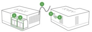
Installation Process:
- De-energize the cable to which Relay will be connected.
- Connect the grid wire to the Relay terminals according to the following scheme:
When installing Relay in the box, lead out the antenna and place it under the plastic frame of the socket. The bigger the distance between the antenna and metal structures, the lower the risk of interfering (and impairment) of the radio signal.![]() Do not shorten the antenna! Its length is optimal for operation within the used radio frequency range!
Do not shorten the antenna! Its length is optimal for operation within the used radio frequency range!
During the installation and operation of Relay, follow the general electrical safety rules and the requirements of electrical safety regulatory acts. It is strictly forbidden to disassemble the device. Do not use the device with damaged power cables.
Do not Install the Relay:
- Outdoors.
- In metal wiring boxes and electrical panels.
- In places with temperature and humidity exceeding the permissible limits.
- Closer than 1 m to a hub.
Maintenance
The device does not require maintenance.
Technical Specification
| Actuating element | Electromagnetic relay |
| The service life of the relay | 200,000 switchings |
| Supply voltage range | 7 – 24 V (DC only) |
| Voltage protection | Yes, min — 6.5 V, max — 36.5 V |
| Maximum load current* | 5 A at 36 V DC, 13 A at 230 V AC |
| Operating modes | Pulse and bistable |
| Pulse duration | 0.5 to 255 seconds |
| Maximum current protection | No |
| Parameter control | Yes (voltage) |
| Device energy consumption | Less than 1 W |
| Frequency band | 868.0 – 868.6 MHz or 868.7 – 869.2 MHz depending on the region of sale |
| Compatibility | Operates only with all Ajax hubs and range extenders |
| Effective radiated power | 3.99 mW (6.01 dBm), limit — 25 mW |
| Modulation of the radio signal | GFSK |
| Maximum distance between the device and the Hub | Up to 1000 m (any obstacles absent) |
| Communication ping with the receiver | 12 – 300 sec (36 sec default) |
| Shell protection rating | IP20 |
| Operating temperature range | From 0°С to +64°С (ambient) |
| Max. temperature protection | Yes, over 65°C at the place of installation or over 85°C inside the Relay |
| Operating humidity | Up to 75% |
| Dimensions | 39 × 33 × 18 mm |
| Weight | 25 g |
![]() If using inductive capacitive load, the maximum commutated current decreases to 3 A at 24 V and to B A V to AC!
If using inductive capacitive load, the maximum commutated current decreases to 3 A at 24 V and to B A V to AC!
Complete Set
- Relay
- Connecting wires — 2 PCS
- Quick Start Guide
Warranty
Warranty for the “AJAX SYSTEMS MANUFACTURING” LIMITED LIABILITY COMPANY products is valid for 2 years after the purchase.
If the device does not work correctly, you should first contact the support service — in half of the cases, technical issues can be solved remotely!The full text of the warranty User Agreement
Technical support: [email protected]
References
Warranty – Ajax Systems
Current product lines of the Ajax security system
Current product lines of the Ajax security system
Relay — Wireless low-current dry contact | Ajax Systems
Wireless panic button with control mode | Ajax Systems
ReX — Intelligent radio signal range extender | Ajax Systems
ocBridge Plus — Module for Ajax devices integration with wired systems
Jeweller radio technology | Ajax Systems
How to create and configure a scenario in the Ajax security system | Ajax Systems Support
Software | Ajax Systems
What is Jeweller Signal Strength Test | Ajax Systems Support
uartBridge — Module for Ajax devices integration with third-party wireless alarms systems
End user agreement – Ajax Systems
Current product lines of the Ajax security system
[xyz-ips snippet=”download-snippet”]