AKG 3249H00010 Perception Wireless Presenter Set Instruction Manual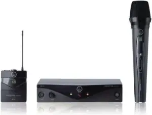
Safety and Environment
Safety
- Do not spill any liquids on the equipment.
- The equipment must only be used in dry rooms.
- The equipment must only be opened, serviced, and repaired by authorised personnel. The equipment contains no user-serviceable parts.
- Before connecting the equipment to power, check that the AC mains voltage stated on the supplied AC adapter is identical to the AC mains voltage available where you will use the equipment.
- Only operate the equipment with the supplied AC adapter with a 12-VDC output. Using adapters with a different output voltage or current type may cause serious damage to the unit.
- If any solid object or liquid should get into the equipment, shut down the system immediately. Disconnect the AC adapter from the power outlet at once and have the equipment checked by our customer service department.
- If the equipment is not going to be used for a long time, disconnect the AC adapter from the power outlet. Please note that if you turn the equipment off while leaving the AC adapter plugged in, it is not fully isolated from the power supply.
- Do not place the equipment near heat sources such as radiators, heating ducts, amplifiers, etc. and do not expose it to direct sunlight, excessive dust, moisture, rain, mechanical vibrations, or shock.
- To avoid hum or interference, route all audio lines, particularly those connected to the microphone inputs, away from power lines of any type. If you use cable ducts, be sure to use separate ducts for the audio lines.
- Clean the equipment with a moistened (not wet) cloth only. Be sure to disconnect the AC adapter from the power outlet before cleaning the equipment. Never use caustic or scouring cleaners or cleaning products containing alcohol or solvents since these may damage the enamel and plastic parts.
- Only use the equipment for the applications described in this manual. AKG cannot accept any liability for damages resulting from improper handling or misuse
Environment
- The power supply unit consumes a small amount of electricity even when the unit is switched off. To save energy, unplug the power supply unit from the socket if you are not going to be using the unit for some time.
- The packaging is recyclable. Dispose of the packaging in an appropriate recycling collection system.
- If you scrap the unit, separate the case, electronics and cables and dispose of all the components in accordance with the appropriate waste disposal regulations.
Description
Introduction
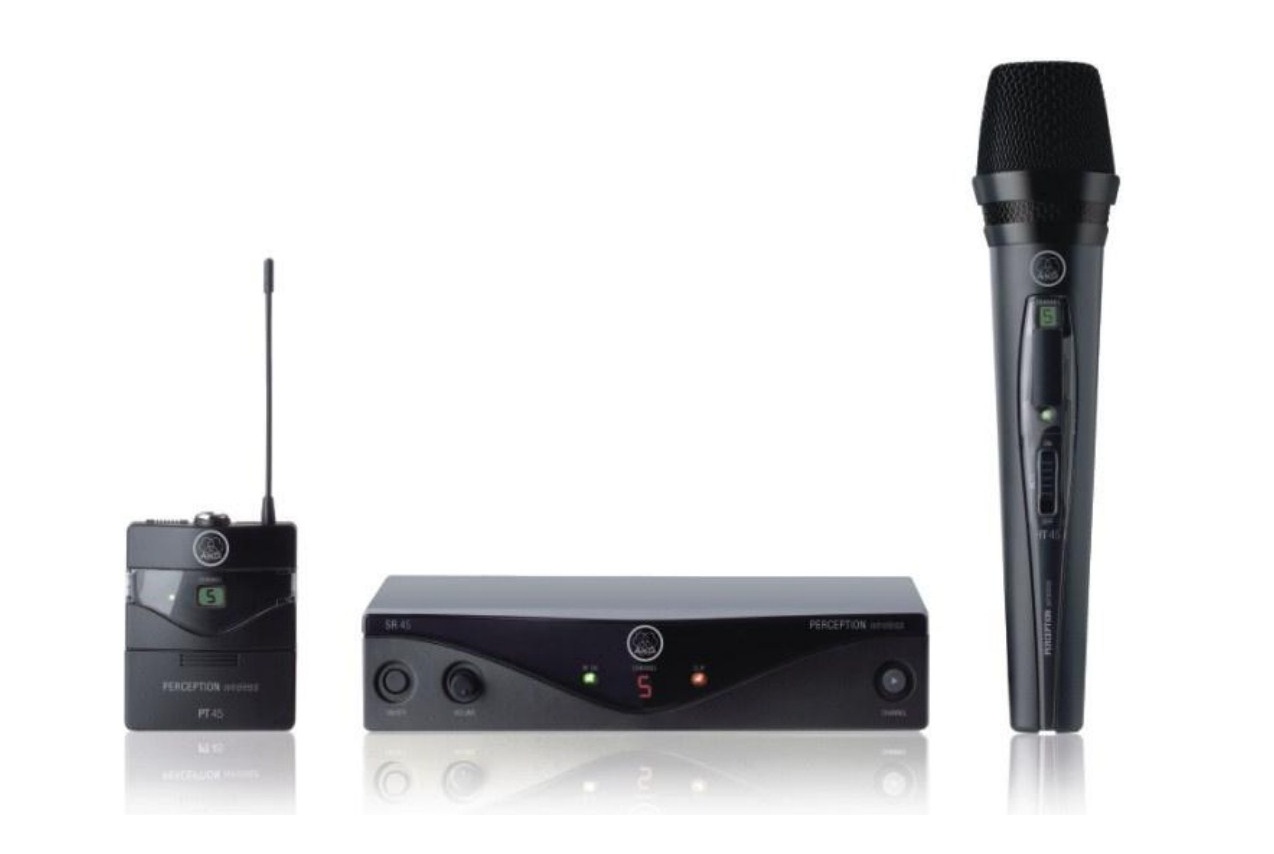
Thank you for purchasing an AKG product. This Manual contains important instructions for setting up and operating your equipment. Please take a few minutes to read the instructions below carefully before operating the equipment. Please keep the Manual for future reference. Have fun and impress your audience!
Scope of supply
The Perception wireless is available in 4 sets with receiver SR 45
Vocal Set
- 1 HT 45 handheld transmitter
- 1 tripod adapter
- 1 AA battery
- 1 SR 45 receiver
- 1 SMPS switched mode power supply
- 1 guarantee card
- 1 frequency table
- 1 Manual Supplement sheet
Presenter Set
- 1 PT 45 bodypack transmitter
- 1 AA battery
- 1 CK 55 L lavalier microphone with attachment clip
- 1 W 444 windshield
- 1 SR 45 receiver
- 1 SMPS switched mode power supply
- 1 guarantee card
- 1 frequency table
- 1 Manual Supplement sheet
Instrumental Set
- 1 PT 45 bodypack transmitter
- 1 AA battery
- 1 MKG L cable
- 1 SR 45 receiver
- 1 SMPS switched mode power supply
- 1 guarantee card
- 1 frequency table
- 1 Manual Supplement sheet
Sports Set
- 1 PT 45 bodypack transmitter
- 1 AA battery
- 1 C 544 L headset microphone
- 4 moisture shields
- 1 W 444 windshield
- 1 SR 45 receiver
- 1 SMPS switched mode power supply
- 1 guarantee card
- 1 frequency table
- 1 Manual Supplement sheet
Check that the packaging contains all of the items listed for your system. If anything is missing, please contact your AKG dealer.
Optional Accessories
For optional accessories, refer to the current AKG catalog or folder, or visit www.akg.com. Your dealer will be glad to help.
SR 45 receiver
The SR 45 is a stationary receiver for use with all transmitters of the Perception wireless system
.The SR 45 operates within a switching bandwidth of up to 30 MHz in the 500 to 865 MHz UHF carrier frequency range and offers up to 8 selectable carrier frequencies.
Front panel
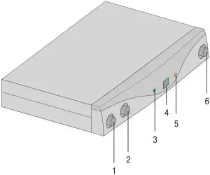 Figure 1: Front panel controls on SR 45 receiver
- ON/OFF: On/off button.
- VOLUME: This retractable rotary control allows continuous adjustment of the audio output level.
- RF OK: This LED lights up to indicate that signal is being received. If no signal is received or the automatic squelch is on, the RF OK LED goes out and the audio output is muted.
- Display: Shows the selected receiving channel.
- CLIP: This LED lights up if the audio level is too high.
- CHANNEL: This button allows you to select one of up to 8 different carrier frequencies within the receiver’s carrier frequency range.
Rear panel
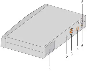 Figure 2: Rear panel controls on SR 45 receiver
- Carrier frequency label: A label indicating the carrier frequency range and up to 8 carrier frequencies is affixed to the rear panel of the receiver.
- SQUELCH: The automatic squelch circuit switches the receiver off if the received signal is too weak, in order to suppress the interference noise or background noise of the receiver while the transmitter is off. Set the squelch control to minimum before switching on the receiver for the first time.
- AUDIO OUT/BALANCED: Balanced audio output to 3-pin XLR connector. Can be connected to a microphone input on a mixer, for example.
- AUDIO OUT/UNBALANCED: Unbalanced audio output to 1/4″ (6.3 mm) mono jack socket.Can be connected to a guitar amplifier, for example.
- Strain relief for the feeder cable of the supplied AC adapter.
- DC IN: Input connector for the supplied AC adapter.
HT 45 handheld transmitter
The HT 45 handheld transmitter operates within a switching bandwidth of up to 30 MHz in the 500 to 865 MHz UHF carrier frequency range and offers up to 8 selectable carrier frequencies. The transmitter uses an antenna integrated within the housing.
The microphone capsule in the transmitter has a cardioid pickup pattern. It provides low handling noise sensitivity, high gain before feedback and brilliant sound quality, as well as a built-in wind and pop filter to reduce wind and breath noise.
Controls
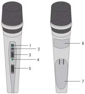
- Display: Shows the selected transmitting channel.
- CHANNEL: This button allows you to select one of up to 8 different carrierfrequencies within the transmitter’s carrier frequency range.
- GAIN: This slide switch allows you to set the audio input sensitivity of the transmitter to one of two positions: “HI” = high input sensitivity, “LOW” = low input sensitivity.
- Status LED: Indicates the transmitter’s operating status.LED lit green: Battery is OK.LED lit red: From the moment the LED changes to red, the battery capacity will provide a maximum of one operating hour. We recommend replacing the battery with a new one as soon as possible.
- On/off switch: This slide switch has three positions:ON: Power to the transmitter is on.MUTE: The audio signal delivered by the microphone is muted while power and the RF carrier frequency remain on.OFF: Power to the transmitter is off.NOTEIf you use a rechargeable battery, the LED will change to red approximately 15 minutes before the battery goes flat.
- Carrier frequency label: The label above the battery compartment indicates the carrier frequency range and up to 8 carrier frequencies.
- Battery compartment cover: See Inserting and testing batteries in the handheld/bodypack transmitters (Page 26)
PT 45 bodypack transmitter
You can use the PT 45 bodypack transmitter with both dynamic microphones and condenser microphones operating on a supply voltage of approx. 4 V. Naturally you may also connect an electric guitar, electric bass or keytar.
The PT 45 operates within a switching bandwidth of up to 30 MHz in the 500 to 865 MHz UHF carrier frequency range and offers up to 8 selectable carrier frequencies.
Controls
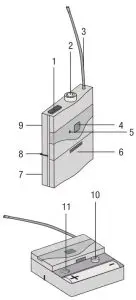
- On/off switch: This slide switch has three positions:ON: Power to the transmitter is on.MUTE: The audio signal delivered by the microphone or instrument is muted while power and the RF carrier frequency remain on.OFF: Power to the transmitter is off.
- Audio input: 3-pin mini XLR connector with both mic and line level pins that automatically match the connector pinout of the recommended AKG microphones or optional MKG L guitar cable.
- Antenna: Permanently connected, flexible antenna.
- Display: Shows the selected transmitting channel.
- Status LED: Indicates the transmitter’s operating status.LED lit green: Battery is OK.LED lit red: From the moment the LED changes to red, the battery capacity will provide a maximum of one operating hour. We recommend replacing the battery with a new one as soon as possible.NOTEIf you use a rechargeable battery, the LED will change to red approximately 15 minutes before the battery goes flat.
- Battery compartment cover with integrated screwdriver.
- Viewing window: The viewing window lets you check if there is a battery or rechargeable battery inside the battery compartment.
- Belt clip for fixing the transmitter to your belt.
- Carrier frequency label: A label indicating the carrier frequency range and up to 8 carrier frequencies is affixed to the rear panel of the transmitter.
- CHANNEL: This button allows you to select one of up to 8 different carrier frequencies within the transmitter’s carrier frequency range.
- GAIN: This rotary control allows you to match the transmitter input gain to the connected microphone or instrument.
Microphones, guitar cable
The PT 45 has been designed specifically for use with the following AKG microphones:
- CK 55 L, C 417 L, C 520 L, C 555 L, C 544 L, C 577
- C 516 ML, C 518 ML, C 519 ML, C 411
- The MKG L guitar cable from AKG lets you connect an electric guitar, electric bass or keytar to the bodypack transmitter.
The MKG L guitar cable is included in the Instrumental Set and is also available separately as an accessory.
Setting up
NOTE
- Before setting up your Perception wireless, check that the transmitter and receiver are tuned to the same frequency. The wireless connection will not work if the receiver and transmitter are tuned to different frequencies.
- Never use both outputs (BALANCED and UNBALANCED) at the same time. This can cause loss of signal and increased noise.
Positioning the receiver
- Set up the receiver as a free-standing unit.
- Reflections off metal parts, walls, ceilings, etc. or the shadow effects of musicians and other people may weaken or cancel the direct transmitter signal.
For best results, set up the receiver as follows:
- Place the receiver near the performance area (stage). Make sure, though, that the transmitter will never be any closer to the receiver than 10 ft (3 m). Optimum separation is 16 ft (5 m).
- Check that you can see the receiver from where you will be using the transmitter.
- Place the receiver at least 5 ft. (1.5 m) away from any large metal objects, walls, scaffolding, ceilings, etc.
Connecting the receiver to a balanced input
- Use an XLR cable to connect the BALANCED output on the back of the receiver to a balanced microphone input (XLR socket) on the mixer or amplifier.
- Turn the VOLUME control on the receiver fully anticlockwise to set the receiver output to mic level.
Connecting the receiver to an unbalanced input
- Use a standard 1/4″ (6.3 mm) jack cable to connect the UNBALANCED output on the back of the receiver to an unbalanced 1/4″ (6.3 mm) line input jack on the mixer or amplifier.
- Turn the VOLUME control on the receiver fully clockwise to set the receiver output to line level.
NOTE
To avoid hum interference, do not use audio cables that are longer than 10 feet (3 m).
Connecting the receiver to power
- Check that the AC mains voltage stated on the included power supply is identical to the AC mains voltage available where you will use your system. Using the power supply with a different AC voltage may wreck the unit.
- Plug the feeder cable of the included power supply into the DC IN socket on the receiver.
- Plug the AC adapter into a power outlet.
- Press the ON/OFF switch to switch the receiver on.
Inserting and testing batteries in the handheld/bodypack transmitters
- Depress the snap hook on the battery compartment cover.
- Pull the battery compartment cover off the transmitter in the direction shown by the arrow.
- Insert the supplied battery into the battery compartment conforming to the polarity marks.The transmitter will not function if you insert the battery the wrong way round.
- To turn the transmitter on, set the on/off switch to “ON”.If the battery is in good condition, the status LED will be lit green.If the status LED is lit red, the battery will be flat within about one hour. Replace the battery with a new one as soon as possible.If the status LED is not lit, the battery is flat. Insert a new battery.NOTEIf you use a rechargeable battery, the LED will change to red approximately 15 minutes before the battery goes flat.
- To close the battery compartment, slide the battery compartment cover onto the battery compartment from below until the snap hook engages.
Setting the frequency
- Switch the receiver on or, if it is already on, press CHANNEL. The selected channel (e.g. 1) blinks for 3 seconds after which it is displayed without blinking, indicating that the selected channel is active.
- During those 3 seconds, press CHANNEL to obtain the required channel number. Each press of the button increases the channel number by one.
- Once you have reached the required channel number, the display blinks for a further 3 seconds after which the channel you have just selected becomes active.
Setting up the handheld transmitter
- Set the SQUELCH control on the receiver to minimum and switch the receiver on.
- To turn the handheld transmitter on, set the on/off switch to “ON”.
- Switch on your PA system or amplifier.
- Speak or sing into the microphone and watch the LEDs on the receiver:
- If the CLIP LED does not light up at all, the input sensitivity of the transmitter is too low. Set the GAIN to “HIGH”.
- If the CLIP LED lights up frequently or all the time, the input sensitivity of the transmitter is too high. Set the GAIN to “LOW”.
- Set the volume of the PA system or amplifier referring to the appropriate instruction manual or by ear.
Setting up the bodypack transmitter
The PT 45 bodypack transmitter has been designed for use with the CK 55 L, C 411, C 417 L, C 520 L, C 555 L, C 516 ML, C 518 ML and C 519 ML microphones from AKG. If you wish to connect other microphones from AKG or other manufacturers to the PT 45, please note that you may have to rewire the existing connector of your microphone or replace it with a 3-pin mini XLR connector.
Audio input pinout:Pin 1: shieldContact 2: audio inphase (+)Pin 3: supply voltage
A 4V positive supply voltage for condenser microphones is available on pin 3.
ATTENTION
AKG cannot guarantee that the PT 45 bodypack transmitter will work perfectly with products from other manufacturers and any damage that may result from such use is not covered by the AKG warranty scheme.
Connecting a microphone
- Remove the battery compartment cover.
- Plug the mini XLR connector on the cable of your microphone into the audio input socket on the bodypack transmitter.
- Turn the bodypack transmitter on by setting the on/off switch to “ON”.
- Set the SQUELCH control on the receiver to minimum and switch the receiver on.
- Set the transmitter and receiver to the same frequency.
- Speak or sing into the microphone.
- Use the screwdriver integrated in the battery compartment cover to set the GAIN control to a position where the CLIP LED on the receiver will flash occasionally.
- Replace the battery compartment cover on the transmitter.
Connecting an instrument
- Remove the battery compartment cover.
- Plug the jack plug on the MKG L guitar cable into the output jack of your instrument and the mini XLR connector on the guitar cable into the audio input socket of the bodypack transmitter.
- Turn the bodypack transmitter on by setting the on/off switch to “ON”.
- Set the SQUELCH control on the receiver to minimum and switch the receiver on.
- Play your instrument.
- Use the screwdriver integrated in the battery compartment cover to set the GAIN control to a position where the CLIP LED on the receiver will flash occasionally.
- Replace the battery compartment cover on the transmitter.
Before the soundcheck
- Move the transmitter around the area where you will use the system to check the area for “dead spots”, i.e. places where the field strength seems to drop and reception deteriorates.If you find any dead spots, try to eliminate them by repositioning the receiver. If this does not help, avoid the dead spots.
- If the RF OK LED on the receiver goes out, this means no signal is being received or the squelch is active.Switch the transmitter on, move closer to the receiver or adjust the squelch level to the point where the green RF OK LED lights up.
- If interference noise occurs, adjust the squelch level until the interference noise goes away.
NOTE
Do not set the squelch level higher than necessary. The higher the squelch level, the lower the sensitivity of the receiver and hence the smaller the range between transmitter and receiver.
Microphone technique
HT 45 handheld transmitter
A handheld vocal microphone provides many ways of shaping the sound of your voice as it is heard over the sound system.
The following sections contain useful hints on how to use your HT 45 handheld transmitter for best results.
Working distance and proximity effect
Basically, your voice will sound bigger and mellower, the closer you hold the microphone to your lips. Moving away from the microphone will produce a more reverberant, more distant sound as the microphone will pick more of the room’s reverberation.
You can use this effect to make your voice sound aggressive, neutral, sensual, etc. simply by altering your distance from the microphone.
The proximity effect is a powerful increase in low frequency response that occurs when a sound source is close to a microphone (less than 2 inches / 5 cm). It gives more “body” to your voice and an intimate, bass-heavy sound.
Angle of incidence
Sing to one side of the microphone or above and across the top of the microphone. This provides a well-balanced, natural sound.
If you sing directly into the microphone, it will not only pick up excessive breath noise but also overemphasise “s”, “sh”, “tch”, “p”, and “t” sounds.
Feedback
Feedback occurs when part of the sound projected by the loudspeakers is picked up by a microphone, amplified and fed back to the speakers. Above a certain volume (the feedback threshold) this process becomes a vicious circle, making the sound system howl and screech.The only solution is to turn down the volume.
To reduce the danger of this happening, the microphone of the HT 45 has a cardioid pickup pattern.
This means that the microphone is most sensitive to sounds arriving from in front of it (your voice), while picking up hardly any sound arriving from the sides or rear (from monitor speakers for instance).
To maximize gain before feedback, place the PA speakers in front of the microphones (along the front edge of the stage)
If you use monitor speakers, be sure never to point any microphone directly at the monitors or at the PA speakers.
Feedback may also be triggered by resonances (due to the room acoustics), particularly in the low frequency range, and thus indirectly by the proximity effect. In this case, it is often enough to move away from the microphone a little to stop the feedback.
Backing vocals
- Never let more than two people share a microphone.
- Backing vocalists should not sing at more than 35° to the microphone axis.The microphone is very insensitive to sounds arriving from the side. If the two vocalists were to try and sing into the microphone at an angle of more than 35° to the microphone axis, you would have to turn up the level of the microphone channel high enough to cause a feedback problem.
PT 45 bodypack transmitter
CK 55 L lavalier microphone
Fix the microphone to the supplied lavalier clip or to the optional H 41/1 tiepin.
- Clip the microphone onto the speaker’s clothing, as close as possible to his or her mouth.NOTEThe closer the microphone is to the speaker’s mouth, the less danger there is of feedback.
- Make sure to aim the microphone towards the user’s mouth.
C 544 L headset microphone
Putting on the microphone
- Put the microphone on.
- Bend the gooseneck so that the microphone sits to one side in front of the corner of your mouth.
NOTE
- If you hear excessive pop noise (“p” and “t” sounds are overemphasised unnaturally), move the microphone capsule further away from your mouth (back or down).
- If the microphone sounds “thin” or flat, move the microphone capsule closer to your mouth.
- Find the optimum position during the soundcheck.
Windshield
If (for instance,on an open-air stage) excessive wind or pop noise becomes audible, attach the supplied foam windshield to the microphone.
- Slide the windshield onto the microphone capsule.
- Pull the windshield over the outer end of the microphone capsule.
Moisture shield
A special moisture shield on the microphone capsule makes it harder for moisture and makeup to penetrate into the microphone.
This prevents the microphone apertures from being clogged by perspiration or makeup, which would make the sound dull and reduce the sensitivity of the microphone. Therefore, you should never remove the moisture shield from the microphone.
The C 544 L headset microphone includes a replacement moisture shield in case the first one gets damaged or lost.
Cleaning
Surfaces Internal windshield of handheld transmitter
Use a soft cloth moistened with water to clean the surfaces.
- Unscrew and remove the wire-mesh cap of the handheld transmitter.
- Take the windshield (foam insert) out of the wire-mesh cap.
- Wash the windshield in mild soap suds.
- As soon as the windshield has dried, replace it in the wire-mesh cap and screw the wiremesh cap onto the handheld transmitter.
Troubleshooting
| Problem | Possible cause | Remedy |
| No sound | AC adapter is not connected to receiver and/or power outlet. | Connect AC adapter to receiver and/or power outlet. |
| Receiver is OFF. | Push ON/OFF switch to switch receiver ON. | |
| Receiver is not connected to mixer or amplifier. | Connect receiver output to mixer or amplifier input. | |
| VOLUME control on receiver is at zero. | Turn up VOLUME control. | |
| Microphone or instrument is not connected to bodypack transmitter. | Connect microphone or instrument to audio input on bodypack. | |
| Transmitter has a different frequency range or is tuned to a different frequency from the receiver. | Use a transmitter with the same frequency range as the receiver or tune both to the same frequency. | |
| Transmitter on/off switch is at “OFF” or “MUTE”. | Set transmitter on/off switch to “ON”. | |
| Transmitter batteries are not inserted properly. | Insert batteries conforming to “+” and “-” marks. | |
| Transmitter batteries are flat. | Replace transmitter batteries. | |
| Transmitter is too far away from receiver or squelch level set too high. | Move closer to receiver or reduce squelch level. | |
| Obstructions between transmitter and receiver. | Remove obstructions. | |
| No line of sight between transmitter and receiver. | Avoid spots where you cannot see receiver. | |
| Receiver is too close to metal objects. | Remove interfering objects or move receiver
away from them. |
|
| Noise, crackling, unwanted signals | Antenna position. | Move receiver to a different location. |
| Interference from other wireless systems, TV, radio, walkie-talkies, or defective electrical appliances or installations. | Switch off interference sources or defective appliances or use a Perception wireless tuned to a different frequency; have electrical
installation checked. |
|
| Distortion | GAIN control is set too high or too low. | Turn GAIN control up or down until distortion goes away. |
| Interference from other wireless systems, TV, radio, walkie-talkies, or defective electrical appliances or installations. | Switch off interference sources or defective appliances or use a Perception wireless tuned to a different frequency; have electrical installation checked. | |
| Antenna position. | Move receiver to a different location. If dead spots persist, mark and avoid them. |
Specifications
|
– |
HT 45 | PT 45 | SR 45 |
| Carrier frequency range | 500 – 865 MHz | 500 – 865 MHz | 500 – 865 MHz |
| Modulation | FM | FM | FM |
| Audio bandwidth | 70 – 20,000 Hz | 40 – 20,000 Hz | 40 – 20,000 Hz |
| T.H.D. at 1 kHz | typ. 0.8% | typ. 0.8% | typ. 0.8% |
| Signal/noise ratio | typ. 105 dB(A) | typ. 105 dB(A) | typ. 105 dB(A) |
| RF output | 10 mW | 10 mW | |
| Power requirement | 1x 1.5 V AA size battery | 1x 1.5 V AA size battery | – |
| Battery life | 10 hours | 10 hours | – |
| Squelch threshold | – | – | -100 to -70 dBm adjustable |
| Audio outputs | – | – | Balanced XLR and unbalanced 1/4″ (6.3 mm) jack: adjustable from mic to line level. Output level at rated deviation: 500 mV rms |
| Dimensions | 229 x 53 x 53 mm | 60 x 74 x 30 mm | 200 x 190 x 44 mm |
| Net weight | 214 g | 60 g | 360 g |
 report this ad
This product conforms to the standards listed in the Declaration of Conformity. To order a free copy of the Declaration of Conformity, visit http://www.akg.com or contact [email protected].
References
[xyz-ips snippet=”download-snippet”]