![]() Smart IntercomX915XQuick Guide
Smart IntercomX915XQuick Guide
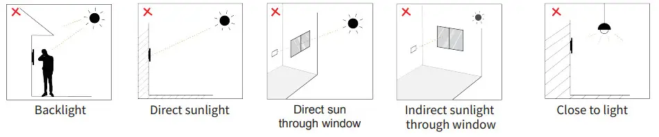
Installation Environment
Indoor and outdoor installation is supported.If installing the device outdoors, please do not place the device under direct sunlight.If installing the device indoors, please keep the device at least 2 meters away from light, and at least 3 meters away from the window and door.
Attention: Biometric recognition products may not be 100% accurate and applicable to all scenarios and environments. For higher security purposes or scenarios, please set up an access authentication combination.
Step 1:Wall-mounting Box or Flush-mounting Box Installation
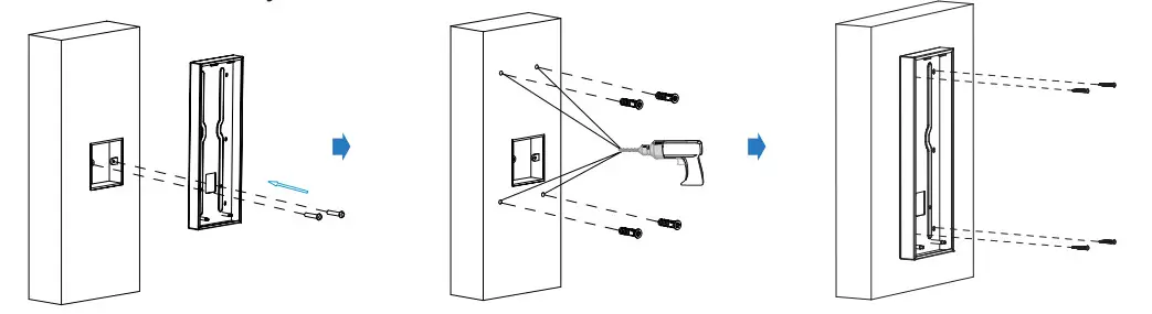
1. Wall-Mounting1.1 With 86×86 mm embedded junction box in the wall
 |
||
| Fix the wall-mounting box onto the embedded box (86) with two M4x30 crews, mark the positions of the four holes of the wall mounting box at the hole center. | Take off the box and drill the four marked holes using a 5 mm drill bit hand drill before inserting the plastic wall anchors into the drilled holes. | Place the wall mounting box closely against the wall while lining up its four holes with their corresponding drilled holes and then fix the wall mounting box on the wall by tightening the four ST4 x 20 screws to the plastic wall anchors. |
1.2 Without embedded junction box in the wall
 |
||
| According to the position of the wire on the wall, put the wall-mounting box closely onto the wall and mark the four positioning holes, while making sure that relative positions between the wall-mounting box and the wiring hole are correct. | Drill the marked holes using 5 mm drill bit hand drill before inserting a plastic wall anchor into the drilled holes. | Place the wall-mounting box closely against the wall while lining up its four holes with their corresponding drilled holes and then fix the wall-mounting box on the wall by tightening four ST x 20 screws to the plastic wall anchors. |
Note: It is suggested that you move the bottom edge of the square hole 10 mm away from the wring hole on the wall as highlighted in green in the drawing.
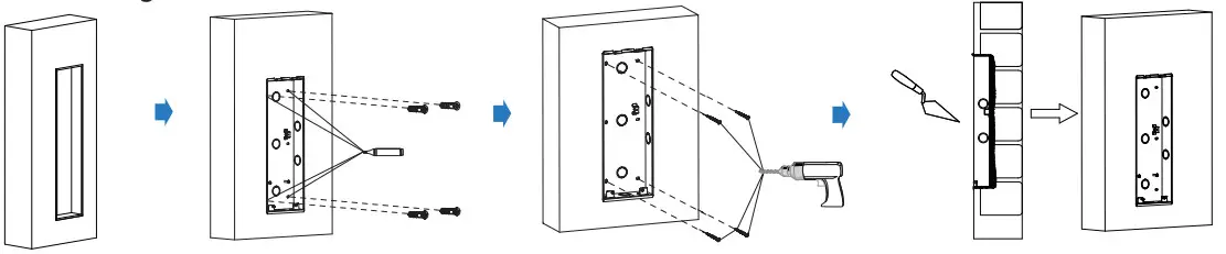
2. Flush-Mounting
 |
|||
| Cut out a square holewith the dimension (height*width*depth = 337*123*43 mm). | Insert the flush-mounting box into the hole and mark the positions of the four holes of the flush-mounting box on the wall, then take off the box and drill the holes on the marked positions using 5 mm drill bit hand drill before inserting the plastic anchors into the drilled holes. | Break off the round knock-out wiring oles and lead the wires through the corresponding hole into the flush-mounting box, then press the flush-mounting box into the square hole. The upper and lower folded edges of the flush-mounting box must fit snugly against the wall. Then fix the box using the four plastic wall anchors and the four ST4x20 screws. | Make sure that the flush- mounting box are well tightened and its upper and lower folded edges are fit snugly against the wall, fill in the gap between the wall and the flush-mounting box using cement or non-corrosive structural adhesive and wait until the cement is hardened before proceeding to the next step. |
STEP 2 :Back cover Installation
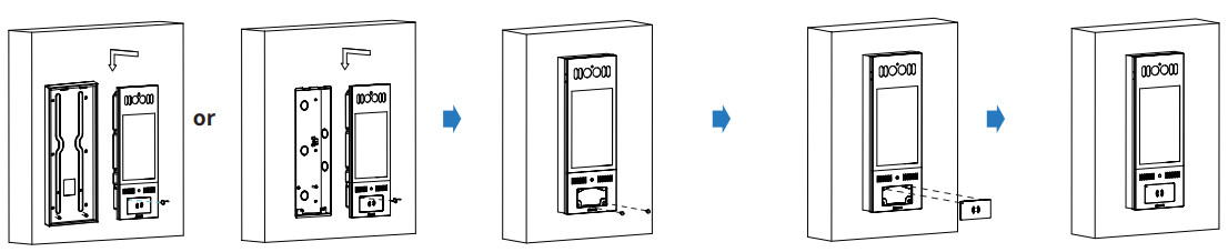 |
|||
| Hang the one end of the rope onto the square hanger on the wall-mounting/flush-mounting box then hang the other end of the rope onto the square hook on the device for the convenience of the later wire installation etc. | Connect the wires to the terminal blocks as needed (for details, refer to “Device Wiring”), then insert the terminal blocks into the corresponding interface of the mainboard as indicated in the drawing according to the number of pins.Note: The pry bar attached can be used to unplug the terminal blocks if needed. | Choose a suitable size rubber plug (small, large, and medium) to hold down the wires, while tearing off the adhesive sticker on the selected rubber plug and stick it onto the X915 back cover and then tear off the adhesive sticker on the other rubber plug of the same size and stick it on to the back cover in the position as indicated in the drawing. | Press the X915 back cover silicone rubber sealing ring into the corresponding groove as indicated by the arrow and then tighten the back cover using the six M3x4 screws to its corresponding holes. |
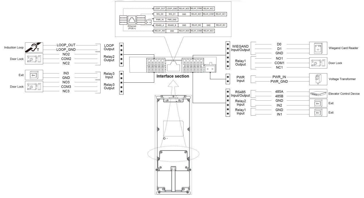
Device Wiring
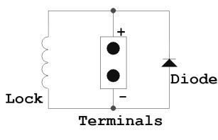
![]() WarningWhen you connect a device containing a coil, such as a relay or an electromagnetic lock, it is necessary to protect the intercom against voltage peak while switching off the induction load. For this way of protection, we recommend a diode 1 A / 200 V (included in the accessories) connected antiparallel to the device.
WarningWhen you connect a device containing a coil, such as a relay or an electromagnetic lock, it is necessary to protect the intercom against voltage peak while switching off the induction load. For this way of protection, we recommend a diode 1 A / 200 V (included in the accessories) connected antiparallel to the device.
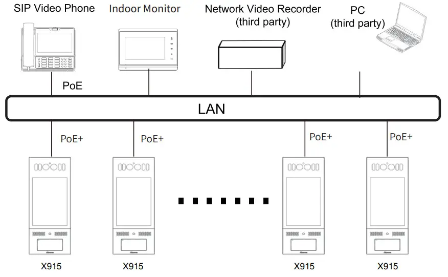
Application Network Topology
Configuration
- IP address Checking: Press 9999 on the dial screen, then press 3888 to enter the system screen and click Info to check the device IP address. X915 uses DHCP by default.
- Account Registration: On the web interface, go to the path Account -> Basic page to register and fill in the account information.(please refer to user manual for more information)
Operation
Make a call:Enter the IP or SIP number and press the Dial tab to make a call.Receive a call:X915 supports Auto Answer by default. Incoming calls from the indoor devices will be answered automatically.Unlock by PIN:Enter the PIN code on the home screen for door access.Unlock by RF Card:Place the configured RF card on the RF card reader area for door access.
Notice Information

Information contained in this document is believed to be accurate and reliable at the time of printing. This document is subject to change without notice, any update to this document can be viewed on Akuvox’ s website: http://www.akuvox.com© Copyright 2020 Akuvox Ltd. All rights reserved.
AKUVOX (XIAMEN) NETWORKS CO., LTD.ADD: 10/F, NO.56 GUANRI ROAD, SOFTWARE PARK II, XIAMEN 361009, CHINAwww.akuvox.com

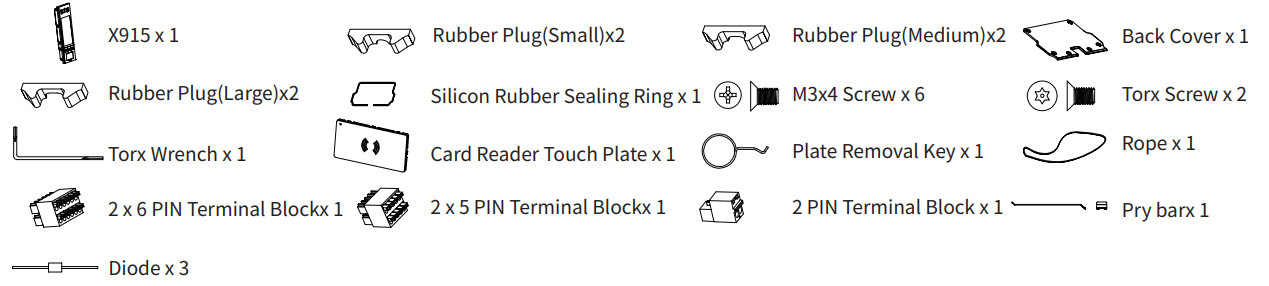
Unpacking
Before you be using the device, please check the version you obtained and ensure that the following items are included in the shipped box:Mainframe Accessories :
Flush-mounting Accessories (Please find in In-Wall Installation Kit box):

Wall-mounting Accessories (Please find in On-Wall Installation Kit box):

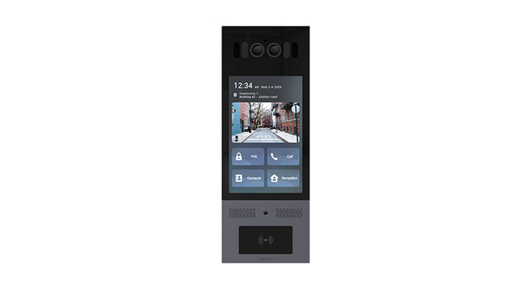
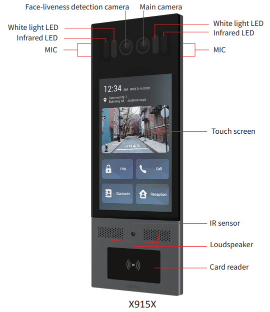
Product Overview
References
[xyz-ips snippet=”download-snippet”]