ALARM COM ADC-V724 1080p Outdoor Wi-Fi Camera with Two-Way Audio Installation Guide
ADC-V724
Pre-installation checklist
- ADC-V724 camera (included)
- AC power adapter (included)
- Wi-Fi (2.4 or 5 GHz) connection to broadband Internet (Cable, DSL, or Fiber Optic) Internet
- A computer, tablet, or smartphone with Wi-Fi is required if the router does not have the Wi-Fi Protected Setup (WPS) feature.
There are two options for connecting the V724 to the Wi-Fi network: Access Point (AP) mode or Wi-Fi Protected Setup (WPS) mode. Use WPS mode if you have easy access to the customer’s router and the router has the WPS feature enabled.
Note that some Internet Service Providers disable the WPS feature on customer routers. AP mode is the most reliable method for installing this device.
In the box
Overview
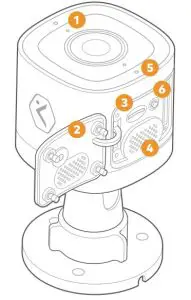
❶ Status LED❷ SD Card Door❸ SD Card Slot
❹ Speaker❺ Microphone❻ WPS/Reset button ![]()
Rubber Plug
A rubber plug has been included with your ADC-V724 at the base of the mount. This rubber plug should only be used if you are mounting directly over a hole in the wall. The rubber plug will provide a seal to prevent water from entering the hole in the wall behind the camera.
In all other installations, please remove the rubber plug. Removing the rubber plug will allow you to route the power cable through the mouse hole without bending or breaking the cable.

Installation
AP Mode (recommended)To ensure sufficient Wi-Fi signal, complete these steps with the camera near its final location but prior to mounting.
- Connect the camera’s AC power adapter and plug it into a non-switched outlet.
- The camera’s LED will begin to blink white. If the LED is not white after two minutes, hold down the WPS/Reset button and release when the LED begins to blink white (about 6 seconds).
- On an Internet-enabled device, connect to the Wi-Fi network ADC-V724 (XX:XX:XX) where XX:XX:XX is the last six characters of the ADC-V724’s MAC address, which is located on the camera or on the packaging.
- On the same device, open a web browser and enter http://v724install in the URL field. Follow the on-screen instructions to add the ADC-V724 to the Wi-Fi network. The LED will briefly turn red before blinking green. The LED will be solid green when the connection is complete.
- Add the device to the account by either selecting the account in MobileTech or by using a web browser and entering the following URL: www.alarm.com/addcamera (you will need the customer user name and password).
- Select the camera from the video device list or enter its MAC address to begin adding the camera. The MAC address is located on the camera or on the packaging.
- Follow the on-screen instructions to finish adding the camera.
You can now power down the camera and install it in its final location using the included hardware. You may configure camera settings from the Customer Website.
WPS Mode (alternate)
To ensure sufficient Wi-Fi signal, complete these steps with the camera near its final location but prior to mounting.
- Connect the camera’s AC power adapter and plug it into a non-switched outlet.
- After the startup process is complete (the camera’s LED will be blinking white), hold down the WPS/Reset button
 and release when the LED begins to blink blue (about 3 seconds).
 - Activate WPS mode on the router. The camera will begin to connect to the Wi-Fi network. The LED will be solid green when the connection is complete.
- Add the device to the account by either selecting the account in MobileTech or by using a web browser and entering the following URL: www.alarm.com/addcamera (you will need the customer user name and password).
- Select the camera from the video device list or enter its MAC address to begin adding the camera. The MAC address is located on the camera or on the packaging.
- Follow the on-screen instructions to finish adding the camera.You can now power down the camera and install it in its final location using the included hardware. You may configure camera settings from the Customer Website.
LED reference guide
Troubleshooting
- If you have issues connecting the camera to the account, power cycle the camera and try again.
- If issues persist, reset the camera to factory defaults. Press and hold the WPS/Reset button until the LED is flashing green and red (about 15 seconds), then release the button. The camera will reboot to factory default.
![]() If the camera was previously installed to an Alarm.com account, it will need to be deleted before it can be installed again.
If the camera was previously installed to an Alarm.com account, it will need to be deleted before it can be installed again.
Prolonged exposure to sunlight in extreme conditions may impact the camera’s performance. The optimal installation location is in a shaded area such as under an eave.
Questions?Visit: answers.alarm.com or contact your service provider
Notices
Federal Communication Commission interference statement
This equipment has been tested and found to comply with the limits for aClass B digital device, pursuant to part 15 of the FCC Rules.
These limits are designed to provide reasonable protection against harmful interference in a residential installation.
This equipment generates, uses and can radiate radio frequency energy and, if notinstalled and used in accordance with the instructions, may cause harmful interference toradio communications.
However, there is no guarantee that interference will not occur in a particular installation. If this equipment does cause harmful interference to radio or television reception, which can be determined by turning the equipment off and on, the user is encouraged to try to correct the interference by one or more of the following measures:
- Reorient or relocate the receiving antenna.
- Increase the separation between the equipment and receiver.
- Connect the equipment into an outlet on a circuit different from that to which the receiver is connected.
- Consult the dealer or an experienced radio/TV technician for help. Changes or modifications not expressly approved by the party responsible for compliance could voidthe user’s authority to operate this equipment.
ISED statementThis device contains licence-exempt transmitters(s)/receiver(s) that comply with Innovation, Science and Economic Development Canada’s licence-exempt RSS(s). Operation is subject to the following two conditions:
- This device may not cause interference.
- This device must accept any interference, including interference that may cause undesired operation of the device.
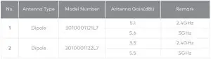
This radio transmitter [IC: 4491A-V723] has been approved by Innovation, Science and Economic Development Canada to operate with the antenna types listed below, with the maximum permissible gain indicated. Antenna types not included in this list that have a gain greater than the maximum gain indicated for any type listed are strictly prohibited for use with this device.
The device for operation in the band 5150-5250 MHz is only for indoor use to reduce thepotential for harmful interference to co-channel mobile satellite systems.
IMPORTANT NOTE:IC Radiation Exposure Statement:This equipment complies with IC RSS-102 radiation exposure limits set forth for an uncontrolled environment. This equipment should be installed and operated with minimum distance 20cm between the radiator & your body.
The transmitter module may not be co-located with any other transmitter or antenna.
CAN ICES-3 (B)/NMB-3(B)The Country Code Selection feature is disabled for products marketed in the US/Canada.For product available in the USA/Canada market, only channel 1~11 can be operated. Selection of other channels is not possible.
8281 Greensboro DriveSuite 100Tysons, VA 22102
© 2021 Alarm.com. All rights reserved.210303 | Made in China.
report this adReferences
[xyz-ips snippet=”download-snippet”]