www.alfatronelectronics.comALFATRON ELECTRONICS GmbH GERMANYALF-PA2B
Preface
Read this user manual carefully before using this product. Pictures shown in this manual are for reference only, different models and specifications are subject to a real product. This manual is for operation instruction only, not for any maintenance usage. The functions described in this version are updated as of April 2020. Any changes of functions and parameters will be informed separately. Please refer to the dealers for the latest details.
FCC Statement
This equipment generates, uses, and can radiate radio frequency energy and, if not installed and used in accordance with the instructions, may cause harmful interference to radio communications. It has been tested and found to comply with the limits for a Class B digital device, pursuant to part 15 of the FCC Rules. These limits are designed to provide reasonable protection against harmful interference in a commercial installation. Operation of this equipment in a residential area is likely to cause interference, in which case the user at their own expense will be required to take whatever measures may be necessary to correct the interference. Any changes or modifications not expressly approved by the manufacture would void the user’s authority to operate the equipment.
Do not dispose of this product with the normal household waste at the end of its life cycle. Return it to a collection point for the recycling of electrical and electronic devices. This is indicated by the symbol on the product, user manual, or packaging. The materials are reusable according to their markings. By reusing, recycling or other forms of utilization of old devices you make an important contribution to the protection of our environment. Please contact your local authorities for details about collection points.
SAFETY PRECAUTIONS
To ensure the best performance from the product, please read all instructions carefully before using the device. Save this manual for further reference.
- Unpack the equipment carefully and save the original box and packing material for possible future shipment.
- Follow basic safety precautions to reduce the risk of fire, electrical shock, and injury to persons.
- Do not dismantle the housing or modify the module. It may result in electrical shock or burn.
- Using supplies or parts not meeting the products’ specifications may cause damage, deterioration, or malfunction.
- Refer all servicing to qualified service personnel.
- To prevent fire or shock hazards, do not expose the unit to rain, moisture or install this product near liquid.
- Do not put any heavy items on the extension cable in case of extrusion.
- Do not remove the housing of the device as opening or removing housing may expose you to dangerous voltage or other hazards.
- Install the device in a place with adequate ventilation to avoid damage caused by overheating. Keep the module away from liquids. Substances spilled into the housing may result in fire, electrical shock, or equipment damage.
- If an object or liquid falls or spills onto the housing, unplug the module immediately.
- Do not forcefully twist or pull the ends of the optical cable. It can cause a malfunction.
- Do not use liquid or aerosol cleaners to clean this unit. Always unplug the power from the device before cleaning.
- Unplug the power cord when left unused for a long period of time.
- Information on disposal for scrapped devices: do not burn or mix with general household waste, please treat it as normal electrical waste.
Product Introduction
The Alfatron PA2B is a compact-size digital amplifier (Class-D) with 3 inputs, 2 lines in, and 1 balanced MIC. Integrated functions include bridge connection, dual-mono, EQ control, microphone mixer, etc. Excellent in varied applications, including classrooms, small meeting rooms, lecture halls, bars, etc.
Features
- 2×20 Ohm as the default amplifier output.
- Bridge connection function. Users can switch the Mini Digital Amplifier to be by bridge connection.
- Two stereo audio inputs, switchable via buttons, IR remote & RS232.
- Volume/Bass/Treble controllable via buttons, IR remote & RS232.
- MIC port supports both balanced and unbalanced signals, suppressing the external noise effectively.
- Line audio output at 3.5mm jack, with volume control.
- Dual-mono function. Users can sum up the stereo audio to two times mono audio.
- MIC mixer function. The microphone will be mixed to the line audio output and be controlled separately.
- MIC input supports 48V phantom power, dynamic MIC, and wireless MIC.
- Auto noise gate. It keeps detecting the audio and MIC input, will mute the output when there is no input.
- Ultra-low inrush current, no need for power sequencing. This allows multiple Mini Digital Amplifiers to be powered on simultaneously without overloading power circuits.
- Convection cooled; a fan is not required.
- Antistatic case design: providing good protection for long-term and stable performance.
Package List
- 1 x PA2B mini amplifier
- 2 x Pluggable Terminal Blocks
- 1 x RS232 Cable
- 1 x Power Adapter
- 1 x Power Cord
- 4 x Plastic Cushions
- 1 x User Manual
Optional Accessories
- IR remote control is available separately for purchasing.
- IR receiver is available separately for purchasing.
Note: Please ensure listed accessories are all included, should it not be, please contact the dealer.
System Connection
Audio Output
- Default Output: The default output of the amplifier is Output connection is pictured below:
- Bridge Connection: The amplifier has a bridge connection, which would double the output power at It will sum up the left and right input channel to be a mono output, the power is up to 40Watt. The bridge connection is:
- Dual-mono OutputThe amplifier also has the function of double-mono output. It can sum up the left and right channel to be the mono audio output. In this way, both of the outputs are outputting the same mono audio. The connection is:
Microphone Input
The microphone input of Mini Digital Amplifier has three modes, and different modes use different connections, as the picture below:
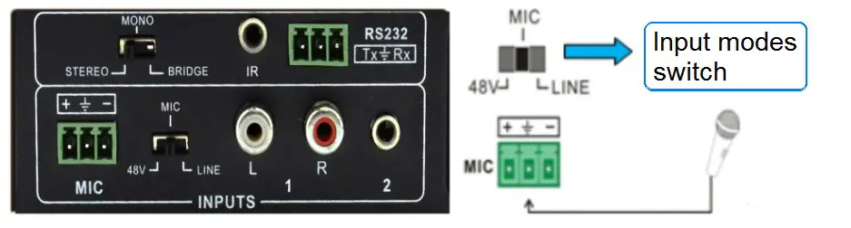
- 48V Phantom Power InputWhen the switch is set to “48V”, the MIC input will provide 48V phantom power. This is usually used as the power supply for a condenser microphone, Connection is: “+” connects to positive, “-” connects to negative, and “
 ” to ground.Note: In this mode, only a condenser microphone can be connected.
 - MIC InputWhen the switch is set to “MIC”, the microphone input is used to connect with a dynamic microphone. There are two different connections:1) Unbalanced connection:“” connects to ground, and “-” connects to signal.“” connects to ground, and “+” connects to signal.2) Balanced connection: “+” connects to positive,”-” connects to negative, and ““connects to ground.
- LINE InputWhen the switch is set to “LINE”, the microphone input is used for connecting with normal audio or wireless microphone output. There are two different connections:1) Unbalanced connection:“” connects to ground, and “-” connects to signal.“” connects to ground, and “+” connects to signal.2) Balanced connection:“+” connects to positive, “-” connects to negative, and “” connects to ground
Panel Control
The panel buttons control the volume/EQ and switching. The following content introduces audio switching and EQ control in detail.
- Audio SwitchingThere are two switchable stereo audio inputs, one 2xRCA input, and one 3.5mm jack input, switchable through the source selection buttons as pictured below:
- Volume/EQ controllingThe line volume and MIC volume can be controlled via the panel buttons. The MIC Volume/LINE volume/LINE bass/LINE treble must be selected via the function button and only then can the up/down/mute via the buttons on the right be done. Pictured below:
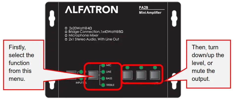
For example, to turn up the line volume, you should select the “LINE” first, and then press the button ” ![]() “.
“.
IR Remote Control (Optional)
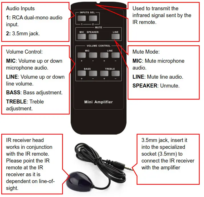
Note: The IR remote, the IR receiver, and the required batteries for the IR remote are all optional accessories available for purchase.
System Diagram
RS232 Command
After setting all required input and output devices according to the system connection introduction, connect a PC for control to the RS232 port. Then install the RS232 control software (e.g. backlight) into the control PC to send RS232 commands to control the amplifier.After installing the RS232 control software, please set the parameters of COM number, bound rate, data bit, stop bit, and the parity bit correctly, you will then be able to send commands in the command sending area.The serial port settings for all RS232 commands are:Baud rate: 9600 Data bit: 8 Stop bit: 1 Parity bit: none
| Command | Function Description | Feedback Code |
| 1A1. | Switching the audio to input 1. | A: 1 -> 1 |
| 2A1. | Switching the audio to input 2. | A: 2 -> 1 |
| OM. | Mute Audio of MIC and Line out. | Mute |
| 1A0. | Mute audio of MIC. | Mute MIC |
| 2A0. | Mute audio of line out. | Mute LIN |
| °A1. | Unmute Audio. | Unmute |
| 3A0. | Switch on Noise Gate. | Gate On |
| 4A0. | Switch off Noise Gate. | Gate Off |
| 600% | Checking the working status. | A: 1 -> 1Volume: 30 Bass: 00Treble: 00 |
| 601% | MIC volume up. | The volume of MIC: 51 |
| 602% | MIC volume down. | The volume of MIC: 51 |
| 603% | Line volume up. | The volume of LINE: 51 |
| 604% | Line volume down. | The volume of LINE: 51 |
| 605% | Bass level up. | Bass of LINE: 04 |
| 606% | Bass level down. | Bass of LINE: 04 |
| 607% | Treble level up. | Treble of LINE: 04 |
| 608% | Treble level down. | Treble of LINE: 04 |
| 609% | Initialization, back to the default setting. | !nit OK |
| 5[x][x]% | Preset MIC volume, [xx] arranges from [00] to [60].61 degrees in total. | The volume of MIC: 50 |
| 7[x][x]% | Preset line volume, [xx] arranges from [00] to [60].61 degrees in total. | The volume of LINE: 50 |
| 8[x][x]% | Preset the bass level, [xx] arranges from [00] to [08].9 degrees in total. | Bass of LINE: 04 |
| 9[x][x]% | Preset the treble level, [xx] arranges from [00] to [08].9 degrees in total. | Treble of LINE: 04 |
Note:
- The letter inside bracket [ ] is the variable code, which is changeable.
- The bracket [ ] is not included in the RS232 commands.
- Any dot “.” after the letters is part of the command.
 report this ad
Example 1:Switching the input 2 to the line out, the RS232 command is: [2A1.].Example 2:Turning up the volume of the line audio, the RS232 command is: [603%].Example 3:Preset the MIC volume to level “21”, RS232 command is: [521%].Example 4:Checking the working status of PA2B Mini Digital Amplifier, the RS232 command is: [600%].
Specifications
| Audio Input | |
| Input | (2) Stereo Audio, (1) MIC |
| Input Connector | (2) RCA. (1) 3.5mm Jack.(1) Pluggable Terminal Block (3P. 3.81mm) |
| Audio Output | |
| Output | (1) Amplifier. (1) Stereo Audio |
| Output Connector | (1) 3.5mm Jack,(1) Pluggable Terminal Block (4P, 5.08mm) |
| Audio Performance | |
| Input Impedance | >10k0 |
| Output Impedance | 500 Analog Output; 4/80 Speaker Output |
| Maximum Rated Power Output | 2×20 watts (4 Ohms) |
| Frequency Response | 20Hz – 20kHz |
| Common Mode Rejection Ratio (CMRR) | >70dB©20Hz-20kHz |
| Signal to Noise Ratio (SNR) | 80dB (Max) |
| Total Harmonic Distortion + Noise (THD+N) | 1% at ‘I kHz: 0.3% at 20kHz at Nominal Level |
| General | |
| Power Supply Input Voltage | 100-240v AC at 50/60 Hz |
| Power Supply | 24V DC at 2.71A |
| Maximum Power Consumption | 45 watts |
| Operation Temperature | 0°C – +40°C |
| Storage Temperature | -10°C – +60°C |
| Storage Humidity | 10%-90% |
| Dimensions (W’1-I’D) | 123mm x40mm x87mm |
| Net Weight | 720g |
Troubleshooting & Maintenance
- When there is no output audio:•Check if there is any signal at the input.•Check if there is any signal at the output.We can check these by using an oscilloscope or a multimeter. If there is no signal input/output, perhaps the input/output cables are broken, or the connectors have come loose, please change for another cable.•Check if the output port number is the same as the controlled one.•If none of the above, please contact your dealer for assessment.
- If the POWER indicator does not work or no response to any operation, please ensure the power cord is properly connected.
- If there is interference in the output sound, please ensure the system is grounded well.
- If the static becomes stronger when connecting the audio connectors, please inspect the grounding and ensure it is well connected, if not, it could damage the converter.
- If the PA2B mini digital amplifier cannot be controlled by the buttons on the panel, RS232 port, nor IR remote, the unit may be damaged. Please send it to the dealer for repair.
After-sales Service
Should you experience problems using the ALF-PA2B, please refer to the manual and troubleshooting and maintenance section (8). Should the error persist, note that any transport costs of the equipment to the distributor are borne by the user during the warranty.
- Product Limited Warranty: Alfatron warrants that its products will be free from defects in materials and workmanship for seven years, which starts from the first day of purchase. Proof of purchase in the form of a bill of sale or receipted invoice which is evidence that the unit is within the warranty period must be presented to obtain warranty service.
- What the warranty does not cover (servicing available for a fee):•Warranty expiration.•The factory-applied serial number has been altered or removed from the product.•Damage, deterioration, or malfunction caused by:•Normal wear and tear.•Use of supplies or parts not meeting product specifications.•No certificate or invoice as proof of warranty.•The product model shown on the warranty card does not match with the product or if the product had been altered.•Damage caused by force majeure.•Servicing is not authorized by Alfatron.•Any other causes which do not relate to a product defect.•Delivery, installation, or labor charges for installation or setup of the product.
- Technical Support: Contact our after-sales department at www.alfatronelectronics.com
Mini Digital Amplifier
Limited warranty in respect of Alfatron Products Only
- This limited warranty covers defects in materials and workmanship in this product.
- Should warranty service be required, proof of purchase must be presented to the Company. The serial number on the product must be clearly visible and not have been tampered with in any way whatsoever.
- This limited warranty does not cover any damage, deterioration, or malfunction resulting from any alteration, modification, improper or unreasonable use or maintenance, misuse, abuse, accident, neglect, exposure to excess moisture, fire, improper packing, and shipping (such claims must be presented to the carrier), lightning, power surges, or other acts of nature. This limited warranty does not cover any damage, deterioration, or malfunction resulting from the installation or removal of this product from any installation, any unauthorized tampering with this product, any repairs attempted by anyone unauthorized by the Company to make such repairs or any other cause which does not relate directly to a defect in materials and/or workmanship of this product. This limited warranty does not cover equipment enclosures, cables, or accessories used in conjunction with this product. This limited warranty does not cover the cost of normal maintenance. Failure of the product due to insufficient or improper maintenance is not covered.
- The Company does not warrant that the product covered hereby, including, without limitation, the technology and/or integrated circuit(s) included in the product, will not become obsolete or that such items are or will remain compatible with any other product or technology with which the product may be used.
- Only the original purchaser of this product is covered under this limited warranty. This limited warranty is not transferable to subsequent purchasers or owners of this product.
- Unless otherwise specified, the goods are warranted in accordance with the manufacturer’s product-specific warranties against any defect attributable to faulty workmanship or materials, fair wear and tear is excluded.
- This limited warranty only covers the cost of faulty goods and does not include the cost of labor and travel to return the goods to the Company’s premises.
- In the event of any improper maintenance, repair, or service being carried out by any third persons during the warranty period without the Company’s written authorization, the limited warranty shall be void.
- A 7 (seven) year limited warranty is given on the aforesaid product were used correctly according to the Company’s instructions, and only with the use of the Company’s components.
- The Company will, at its sole option, provide one of the following three remedies to whatever extent it shall deem necessary to satisfy a proper claim under this limited warranty:
- Elect to repair or facilitate the repair of any defective parts within a reasonable period of time, free of any charge for the necessary parts and labor to complete the repair and restore this product to its proper operating condition.; or
- Replace this product with a direct replacement or with a similar product deemed by the Company to perform substantially the same function as the original product, or Issue a refund of the original purchase price less depreciation to be determined based on the age of the product at the time remedy is sought under this limited warranty.
- The Company is not obligated to provide the Customer with a substitute unit during the limited warranty period or at any time thereafter.
- If this product is returned to the Company this product must be insured during shipment, with the insurance and shipping charges prepaid by the Customer. If this product is returned uninsured, the Customer assumes all risks of loss or damage during shipment. The Company will not be responsible for any costs related to the removal or reinstallation of this product from or into any installation. The Company will not be responsible for any costs related to any setting up this product, any adjustment of user controls, or any programming required for a specific installation of this product.
- Please be aware that the Company’s products and components have not been tested with competitor’s products and therefore the Company cannot warrant products and/or components used in conjunction with competitor’s products.
- The appropriateness of the goods for the purpose intended is only warranted to the extent that the goods are used in accordance with the Company’s installation, classification, and usage instructions.
- Any claim by the Customer which is based on any defect in the quality or condition of the goods or their failure to correspond with specification shall be notified in writing to the Company within 7 days of delivery or (where the defect or failure was not apparent on reasonable inspection by the Customer) within a reasonable time after discovery of the defect or failure, but, in any event, within 6 months of delivery.
- If delivery is not refused, and the Customer does not notify the Company accordingly, the Customer may not reject the goods and the Company shall have no liability and the Customer shall pay the price as if the goods had been delivered in accordance with the Agreement.
- THE MAXIMUM LIABILITY OF THE COMPANY UNDER THIS LIMITED WARRANTY SHALL NOT EXCEED THE ACTUAL PURCHASE PRICE PAID FOR THE PRODUCT.
References
[xyz-ips snippet=”download-snippet”]