www.alfatronelectronics.comALFATRON ELECTRONICS GmbH GERMANYALF- SUK4T
FCC StatementThis equipment generates, uses, and can radiate radio frequency energy and, if not installed and used in accordance with the instructions, may cause harmful interference to radio communications. It has been tested and found to comply with the limits for a Class B digital device, pursuant to part 15 of the FCC Rules. These limits are designed to provide reasonable protection against harmful interference in a commercial installation. Operation of this equipment in a residential area is likely to cause interference, in which case the user at their own expense will be required to take whatever measures may be necessary to correct the interference. Any changes or modifications not expressly approved by the manufacture would void the user’s authority to operate the equipment.
Do not dispose of this product with the normal household waste at the end of its life cycle. Return it to a collection point for the recycling of electrical and electronic devices. This is indicated by the symbol on the product, user manual, or packaging. The materials are reusable according to their markings. By reusing, recycling, or other forms of utilization of old devices you make an important contribution to the protection of our environment. Please contact your local authorities for details about collection points.Surge protection device recommendedThis product contains sensitive electrical components that may be damaged by electrical spikes, surges, electric shock, lightning strikes, etc. Use of surge protection systems is highly recommended to protect and extend the life of your equipment.
Introduction
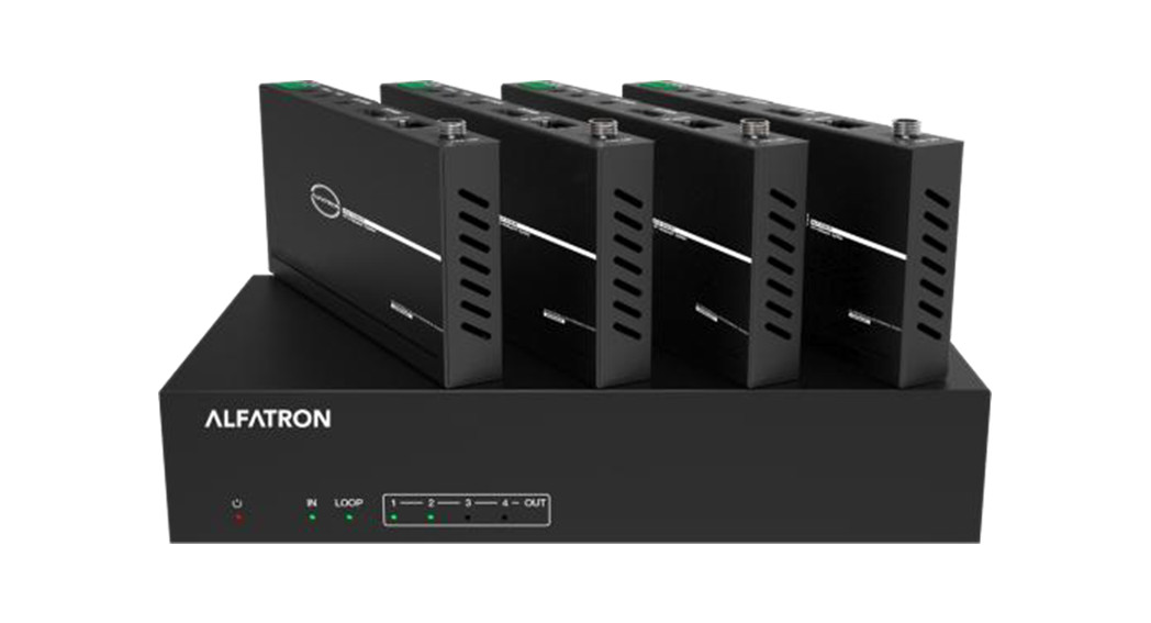
The ALF-SUK4T is an 18Gbps HDMI 1×4 HDBaseT Splitter. The ALF-SUK4T distributes a source signal to four displays and supports video resolution up to 4:4:4. It is designed with 1 HDMI loop output and 4 HDBaseT outputs. The HDMI signal transmission distance could be extended up to 328ft(100m) at a resolution of , or 492ft(150m) at via a single CAT 6/7 cable. The product supports IR and RS-232 signal pass-through, audio extraction function, and advanced EDID management.
Features
- HDMI 2.0b, HDCP 2.2, and HDCP compliant
- Supports 18Gbps video bandwidth
- Supports video resolution up to 4:4:4
- Supports HDR, HDR10+, HLG, and Dolby vision
- Supports up to 7.1CH HD audio pass-through
- Supports digital and analog audio de-embedded output
- Extend the signal transmission distance up to 328ft(100m) at a resolutionof , and 492ft(150m) at via a single CAT 6/7 cable
- Supports 1 HDMI input, 1 HDMI loop output, and 4 HDBaseT outputs.
- IR, RS-232 routed to HDBaseT output
- Advanced EDID management
- Supports one-way POC function (only from transmitter to receiver)
- Compact design for easy and flexible installation
Package Contents
- 1 × 18Gbps HDMI 1×4 HDBaseT Splitter
- 4 × HDBaseT Receiver
- 5 × IR Emitter Cable (1.5 meters)
- 5 × 20K~60KHz IR Receiver Cable (1.5 meters)
- 5 × 3-pin Phoenix Connector
- 1 × 5-pin Phoenix Connector
- 10 × Mounting Ear
- 1 × 24V/2.7A DC Locking Power Adapter
- 1 × User Manual
Specifications
| Technical | |
| HDMI Compliance | HDMI 2.0b |
| HDCP Compliance | HDCP 2.2 |
| Video Bandwidth | 594MHz/18Gbps |
| Video Resolution | Up to 4:4:4 |
| Color Depth | 8-bit,10-bit,12-bit()
8-bit ( YUV4:4:4) 8-bit,10-bit,12-bit( YCbCr 4:2:2/4:2:0) |
| Color Space | RGB 4:4:4, YCbCr 4:4:4 / 4:2:2 / 4:2:0 |
| HDR | Support HDR, HDR10+, HLG, Dolby vision |
| HDMI Audio Formats | LPCM 2.0/2.1/5.1/6.1/7.1, Dolby Digital, Dolby TrueHD, Dolby Digital Plus(DD+), DTS-ES, DTS HD Master, DTS HD-HRA, DTS-X |
| Coaxial Audio Formats | PCM2.0, Dolby Digital / Plus, DTS 2.0/5.1 |
| Analog Audio Formats | PCM 2.0CH |
| ESD Protection | Human body model—±8kV (Air-gap discharge) & ±4kV (Contact discharge) |
| Connection | |
| Input | 1x HDMI Type A (19-pin female) |
| Output | 1xHDMI Type A (19-pin female) 4x HDBaseT OUT [RJ45]
lx Coaxial Audio OUT [RCA] lx UR Audio OUT [5-pin phoenix connector] |
| Control | 1xRS-232 (3-pin phoenix connector) 1x EDID DIP switch [5-pin]
1x IR IN [3.5mm Stereo Mini-jack] lx IR OUT [3.5mm Stereo Mini-jack] |
| Mechanical | |
| Housing | Metal Enclosure |
| Silkscreen Color | Black |
| Dimensions | Transmitter: 220mm (W) x 130mm (D) x 40mm (H) Receiver: 140mm (W) x 65mm (D) x 18mm (H) |
| Weight | Transmitter: 853g Receiver: 246g |
| Power Supply | Input: AC100 – 240V 50/60Hz, Output: DC 24V/2.7A (US/EU standards, CE/FCC/UL certified) |
| Power Consumption | 35W |
| Operation Temperature | 0°C — 40°C / 32°F — 104°F |
| Storage Temperature | -20°C — 60°C / -4°F — 140°F |
| Relative Humidity | 20-90% RH (non-condensing) |
Operation Controls and Functions
Transmitter Front Panel
| No. | Name | Function Description |
| 1 | POWER LED | When the device is powered on, the red power LED will be illuminated. |
| 2 | IN LED | When the HDMI IN port connects an active source device, the green LED will be illuminated. |
| 3 | LOOP LED | When the HDMI LOOP OUT port connects an active display device, the green LED will be illuminated. |
| 4 | OUT(1-4) LED | When the HDBT OUTPUT port connects an HDBaseT Receiver, the corresponding green OUT LED will be illuminated. |
Rear Panel
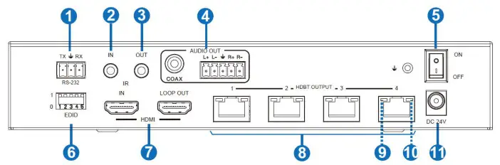
| No. | Name | Function Description |
| 1 | RS-232 | Connect to a PC or control system via a 3-pin phoenix connector cable for three functions:
1, Firmware update; 2, Control the Splitter via RS-232 commands; 3, RS-232 signal pass-through (from transmitter to receiver or from receiver to the transmitter). |
| 2 | IR IN | Connect to IR Receiver cable, the IR receive signal will emit to the “IR OUT” port of the HDBaseT Receiver. |
| 3 | IR OUT | Connect to IR Emitter cable, the IR emit signal is from the “IRIN” port of the HDBaseT Receiver. |
| 4 | AUDIO OUT(COAX, UR) | Coaxial/balanced audio output port connects to amplifier or speaker. |
| 5 | POWER switch | Press this switch to power on/off the device. |
| 6 | EDID DIP switch | Used to set EDID mode. Please refer to Section “6. EDIDMode” for details. |
| 7 | HDMI port | IN: HDMI input port, connects to HDMI source devices such as a DVD or set-top box with an HDMI cable. |
| LOOP OUT: HDMI loop output port connects to the HDMI display device such as a TV or Monitor with an HDMI cable. | ||
| 8 | HDBT OUTPUT port (1-4) | Connects to the HDBT IN port of the HDBaseT receiver with a CAT 6 / 7 cable. |
| 9 | Connection Signal Indicator lamp (Green) | • Illuminating: The transmitter and Receiver are in good connection status.• Flashing: The transmitter and Receiver are in poor connection status.• Dark: The transmitter and Receiver are not connected. |
| 10 | Data Signal Indicator lamp (Orange) | • Illuminating: HDMI signal with HDCP.
• Flashing: HDMI signal without HDCP. • Dark: No HDMI signal. |
| 11 | DC 24V | Plug the DC 24V power supply into the unit and connect the adaptor to an AC outlet. (Note: The transmitter can power the receiver via a CAT 6 / 7 cable.) |
HDBaseT Receiver
| No. | Name | Function Description |
| 1 | Power Indicator | When the receiver is powered on, the power indicator will be illuminated. |
| 2 | SERVICE port | Used for firmware update. |
| 3 | DC 24V | Plug DC 24V/1A power supply into the unit and connect the adapter to an AC outlet.
(Note: The HDBaseT receiver also can be powered by the transmitter via a CAT cable.) |
| 4 | HDBT IN | Connect to the HDBT OUTPUT port on the transmitter with a CAT cable. |
| 5 | Connection Signal Indicator lamp (Green) | • Illuminating: The transmitter and Receiver are in good connection status.
• Flashing: The transmitter and Receiver are in poor connection status. • Dark: The transmitter and Receiver are not connected. |
| 6 | Data Signal Indicator lamp (Orange) | • Illuminating: HDMI signal with HDCP.
• Flashing: HDMI signal without HDCP. • Dark: No HDMI signal. |
| 7 | HDMI OUT | HDMI output port connects to HDMI display device such as a TV or Projector with an HDMI cable. |
| 8 | AUDIO OUT | Audio output port connects to amplifier or speaker. |
| 9 | IR IN | Connects to the IR Receiver cable. The IR signal will send to the IR OUT port of the transmitter. |
| 10 | IR OUT | Connect to the IR emitter cable, the IR signal is from the IR IN port of the transmitter. |
| 11 | RS-232 | 3-pin Phoenix connector for RS-232 command transmission. The RS-232 command will pass through from transmitter to receiver or from receiver to the transmitter. |
IR Pin Definition
Note: When the angle between the IR receiver and the remote control is ± 45 °, the transmission distance is 0-5 meters; when the angle between the IR receiver and the remote control is ± 90 °, the transmission distance is 0-8 meters.
EDID Mode
The defined EDID setting list of the product is shown as below:
| EDID Mode | EDID Description |
| 11111 | 1080P, Stereo Audio 2.0 |
| 11110 | 1080P, Dolby/DTS 5.1 |
| 11101 | 1080P, HD Audio 7.1 |
| 11100 | 1080I, Stereo Audio 2.0 |
| 11011 | 1080I, Dolby/DTS 5.1 |
| 11010 | 1080I, HD Audio 7.1 |
| 11001 | 1080P 3D, Stereo Audio 2.0 |
| 11000 | 1080P 3D, Dolby/DTS 5.1 |
| 10111 | 1080P 3D, HD Audio 7.1 |
| 10110 | 4K2K30Hz_444, Stereo Audio 2.0 |
| 10101 | 4K2K30Hz_444, Dolby/DTS 5.1 |
| 10100 | 4K2K30Hz_444, HD Audio 7.1 |
| 10011 | 4K2K60Hz_420, Stereo Audio 2.0 |
| 10010 | 4K2K60Hz_420, Dolby/DTS 5.1 |
| 10001 | 4K2K60Hz_420, HD Audio 7.1 |
| 10000 | 4K2K60Hz_444, Stereo Audio 2.0 |
| 01111 | 4K2K60Hz_444, Dolby/DTS 5.1 |
| 01110 | 4K2K60Hz_444, HD Audio 7.1 |
| 01101 | 4K2K60Hz_444, Stereo Audio 2.0 HDR |
| 01100 | 4K2K60Hz_444, Dolby/DTS 5.1 HDR |
| 01011 | 4K2K60Hz_444, HD Audio 7.1HDR |
| 01010 | COPY_FROM_LOOP OUT |
| 01001 | COPY_FROM_HDBT OUT1 |
| 01000 | COPY_FROM_HDBT OUT2 |
| 00111 | COPY_FROM_HDBT OUT3 |
| 00110 | COPY_FROM_HDBT OUT4 |
| 00101 | 1080P, Stereo Audio 2.0 |
| 00100 | 1080P, Stereo Audio 2.0 |
| 00011 | 1080P, Stereo Audio 2.0 |
| 00010 | 1080P, Stereo Audio 2.0 |
| 00001 | 1080P, Stereo Audio 2.0 |
| 00000 | PC control mode |
ASCII Commands
The ALF-SUK4T also supports ASCII command control. Connect the RS-232 port of the product to a PC with a 3-pin phoenix connector cable. Then open a Serial Command tool on PC to send ASCII commands to control the product. The ASCII command list about the product is shown as below.
| ASCII Commands | ||||
| Serial port protocol. Baud rate: 115200. Data bits: 8bit Stop bits:1 Check bit: 0 | ||||
| x – Parameter 1
y – Parameter 2 !- Delimiter |
||||
| Command Code | Function Description | Example | Feedback | Default Setting
|
| Power | ||||
| s power z! | Power on/off the device, z4-1(z=0 power off, z=1 power on) | s power 1! | Power on System Initializing… Initialization Finished! FW version x.xx.xx | power on |
| r power! | Get current power state | r power! | power on/power off |
|
| s reboot! | Reboot the device | s reboot! | Reboot.System Initializing… Initialization Finished! FW version x.xx.xx |
|
| System Setup |
|
|||
| help! | List all commands | help! |
|
|
| r type! | Get device model | r type! | ALF-SUK4T |
|
| r status! | Get device current status | r status! | Get the unit all status power, in/out connection. did mode |
|
| r fw version! | Get Firmware version | r fwversion! | MCU BOOT: VX-XX.)Di MCU APP: Vx.xx.xx |
|
| r link in! | Get the connection status of the input port | r link in! | HDMI IN: connect |
|
| r link outy! | Get the connection status of they output port,
y=0-5(0=a11, 1-4=HDBT 1-4, 5 = loop out) |
r link out 1! | HDMI loop out: conned heat output 1: connect |
|
| s reset! | Reset to factory defaults | s reset! | Reset to factory defaults
System Initializing… Initialization Finished! FW version x.xx.xx |
|
| Command Code | Function Description | Example | Feedback | Default Setting |
| Output Setting | ||||
| s hdmi stream z! | Set hdmi loop output stream on/off z=0-1(0:disable.1..enable) | s hdmi stream 1 ! | Enable hdmi loop out stream Disable hdmi loop out stream | enable |
| s hdmi hdcp z! | Set hdmi loop output hdcp on/ off z=0-1(0:disable,1:enable) | s hdmi hdcp 1!
Disable hdmi loop ou |
Enable hdmi loop out hdcp hdcp | enable |
| s hdbt y hdcp z! | Set hdbt output y hdcp on/off, y=0-4(0=311) z=0-1(0:disable, 1:enab4e) | s hdbt 1 hdcp 1!s hdbt 0 hdcp 1! | Enable hdbt output 1 hdcp Disable hdbt output 1 hdcp
Enable hdbt all outputs hdcp Disable hdbt all outputs hdcp |
enable |
| s hdbt y stream z! | Set hdbt output y stream on/ off, y=0-4(0=a11) z=0-1 (0:disable,1:enable) | s hdbt 1 stream 1 !
s hdbt 0 stream 1 ! |
Enable hdbt output 1streamable hdbt output 1streamEnable hdbt all outputs stream Disable hdbt all outputs stream | enable |
| r hdmi stream! | Get hdmi loop out-stream status | r hdmi stream! | Enable hdmi output stream | |
| r hdmi hdcp! | Get hdmi loop out hdcp status | r hdmi hdcp! | Enable hdmi output HDCP | |
| r hdbty hdcp! | Get hdbt output y hdcp status, y=0-4(0=a11) | r hdbt 1 hdcp! | Enable hdbt output 1 hdcp | |
| r hdbt stream! | Get hdbt output y stream
status, y=0-4(0=a11) |
r hdbt 1 stream! | Enable hdbt output 1 stream |
| Command Code | Function Description | Example | Feedback | Default Setting |
| EDID Setting | ||||
| Set input EDID from default EDID z, z=1-27
1. 1080p.Stereo Audio 2.0 2. 1080p.Dolby/DTS 5.1 3. 1080p,HD Audio 7.1 4. 1080i.Stereo Audio 2.0 5. 1080i,Dolby/DTS 5.1 6. 1080i.HD Audio 7.1 7. 30.Stereo Audio 2.0 8. 30.Dolby/DTS 5.1 9. 3D.HD Audio 7.1 10, 4K2K30_444, Stereo Audio 2.0 11, 4K2K30_444,Dolby/DTS5.1 12, 4K2K30_444,HD Audio 7.1 13, 4K2K60_420, Stereo Audio 2.0 14, 4K2K60_420,Dolby/DTS 5.1 15, 4K2K60_420,HD Audio 7.1 16, 4K2K60_444, Stereo Audio 2.0 17, 4K2K60_444,Dolby/DTS 5.1 18, 4K2K60_444,HD Audio 7.1 19, 4K2K60_444, Stereo Audio 2.0 HDR 20, 4K2K60_444. Dolby/DTS 5.1 HDR 21, 4K2K60_444, HD Audio 7.1 HDR 22, copy from hdmi loop out 23. copy from hdbt output 1 24, copy from hdbt output 2 25, copy from hdbt output 3 26, copy from hdbt output 4 27. use userl EDID |
input EDID:1080p. Stereo Audio 2.0 | |||
| s edid in from z! | s edid in from 1! | 1080p,Stereo Audio 2.0 | ||
| Please toggle EDIDdip switch to 00000! | ||||
| s edid userl 00 FF FF FF FF …! | Set used EDID EDID data | edid userl 00 ffffffff….! | userl EDID data: 00 FFFF……. | |
| r edid userl! | Get userl EDID data | r edid userl! | userl EDID data : 00 FF FF FF FF FF FF 00 | |
| r edid in! | Get EDID status of the input | r edid in! | input EDID: 4K2K60_ 444.Stereo Audio 2.0 | |
| r edid in data! | Get the EDID data of the hdmi
input |
r edid in data! | EDID data: 00 FF FF
FF FF FF FF 00………………………. |
| Command Code | Function Description | Example | Feedback | Default Setting |
| RS-232 BYPASS Setting | ||||
| s rs232 bypass hdbt y! | Set RS-232 port connect to HDBT out1 Receiver RS-232 port, y=0-5( 0=a11.
port out 1-4 5=NC) |
s rs232 bypass hdbt 1! | RS-232 connect to HDBT OUT1
RS-232 not connect to HDBT OUT |
Yr° |
| r rs232 bypass! | Get RS-232 port connects to HDBT out receiver RS-232 port | r rs232 bypass! | RS-232 connect to HDBT OUT1
RS-232 connect to al HDBT OUT RS-232 not connect to HDBT OUT |
|
| s device baud w size x stop y parity z! | Set receiver control device COM port setting, w=2400. 4800,9600,19200,38400, 57600.115200, x=7.8
y=1,2, z=none, even,odd |
s device baud 57600 size 8 stop 1 parity none! | receiver device COM port setting baudrate: 57600 data size :8, stop:1 parity: none | |
| s rs232 time x! | set send RS232 command wait time
x=200-5000ms |
s rs232 time 200! | send RS-232 command wait time 200ms | 200ms |
Application Example
report this ad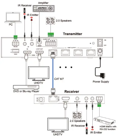
After-sales ServiceShould you experience problems using the ALF-SUK4T, please note that any transport costs of the equipment to the distributor are borne by the user during the warranty.
1) Product Limited Warranty: Alfatron warrants that its products will be freefrom defects in materials and workmanship for seven years, which startsfrom the first day of purchase. Proof of purchase in the form of a bill of saleor receipted invoice which is evidence that the unit is within the warrantyperiod must be presented to obtain warranty service.2) What the warranty does not cover (servicing available for a fee):
- Warranty expiration.
- Factory-applied serial number has been altered or removed from the product.
- Damage, deterioration, or malfunction caused by:
- Normal wear and tear.
- Use of supplies or parts not meeting product specifications.
- No certificate or invoice as proof of warranty.
- The product model shown on the warranty card does not match with the product or if the product had been altered.
- Damage caused by force majeure.
- Servicing not authorized by Alfatron.
- Any other causes which do not relate to a product defect.
- Delivery, installation, or labour charges for installation or setup of the product.
3)Technical Support: Contact our after-sales department at www.alfatronelectronics.com
WarrantyLimited warranty in respect of Alfatron Products Only1.1 This limited warranty covers defects in materials and workmanship in this product.1.2 Should warranty service be required, proof of purchase must be presented to the Company. The serial number on the product must be clearly visible and not have been tampered with in any way whatsoever.1.3 This limited warranty does not cover any damage, deterioration, or malfunction resulting from any alteration, modification, improper or unreasonable use or maintenance, misuse, abuse, accident, neglect, exposure to excess moisture, fire, improper packing, and shipping (such claims must be presented to the carrier), lightning, power surges, or other acts of nature. This limited warranty does not cover any damage, deterioration, or malfunction resulting from the installation or removal of this product from any installation, any unauthorized tampering with this product, any repairs attempted by anyone unauthorized by the Company to make such repairs, or any other cause which does not relate directly to a defect in materials and/or workmanship of this product. This limited warranty does not cover equipment enclosures, cables, or accessories used in conjunction with this product. This limited warranty does not cover the cost of normal maintenance. Failure of the product due to insufficient or improper maintenance is not covered.1.4 The Company does not warrant that the product covered hereby, including, without limitation, the technology and/or integrated circuit(s) included in the product, will not become obsolete or that such items are or will remain compatible with any other product or technology with which the product may be used.1.5 Only the original purchaser of this product is covered under this limited warranty. This limited warranty is not transferable to subsequent purchasers or owners of this product.1.6 Unless otherwise specified, the goods are warranted in accordance with the manufacturer’s product-specific warranties against any defect attributable to faulty workmanship or materials, fair wear and tear being excluded.1.7 This limited warranty only covers the cost of faulty goods and does not include the cost of labor and travel to return the goods to the Company’s premises.1.8 In the event of any improper maintenance, repair, or service being carried out by any third persons during the warranty period without the Company’s written authorization, the limited warranty shall be void.
1.9 A 7 (seven) year limited warranty is given on the aforesaid product were used correctly according to the Company’s instructions, and only with the use of the Company’s components.1.10 The Company will, at its sole option, provide one of the following three remedies to whatever extent it shall deem necessary to satisfy a proper claim under this limited warranty:1.10.1 Elect to repair or facilitate the repair of any defective parts within a reasonable period of time, free of any charge for the necessary parts and labor to complete the repair and restore this product to its proper operating condition.; or1.10.2 Replace this product with a direct replacement or with a similar product deemed by the Company to perform substantially the same function as the original product; or1.10.3 Issue a refund of the original purchase price less depreciation to be determined based on the age of the product at the time remedy is sought under this limited warranty.1.11 The Company is not obligated to provide the Customer with a substitute unit during the limited warranty period or at any time thereafter.1.12 If this product is returned to the Company this product must be insured during shipment, with the insurance and shipping charges prepaid by the Customer. If this product is returned uninsured, the Customer assumes all risks of loss or damage during shipment. The Company will not be responsible for any costs related to the removal or reinstallation of this product from or into any installation. The Company will not be responsible for any costs related to any setting up this product, any adjustment of user controls, or any programming required for a specific installation of this product.1.13 Please be aware that the Company’s products and components have not been tested with competitor’s products and therefore the Company cannot warrant products and/or components used in conjunction with competitor’s products.1.14 The appropriateness of the goods for the purpose intended is only warranted to the extent that the goods are used in accordance with the Company’s installation, classification, and usage instructions.1.15 Any claim by the Customer which is based on any defect in the quality or condition of the goods or their failure to correspond with specification shall be notified in writing to the Company within 7 days of delivery or (where the defect or failure was not apparent on reasonable inspection by the Customer) within aa reasonable time after discovery of the defect or failure, but, in any event, within 6 months of delivery.1.16 If delivery is not refused, and the Customer does not notify the Company accordingly, the Customer may not reject the goods and the Company shall have no liability and the Customer shall pay the price as if the goods had been delivered in accordance with the Agreement.1.17 THE MAXIMUM LIABILITY OF THE COMPANY UNDER THIS LIMITED WARRANTY SHALL NOT EXCEED THE ACTUAL PURCHASE PRICE PAID FOR THE PRODUCT.
References
[xyz-ips snippet=”download-snippet”]