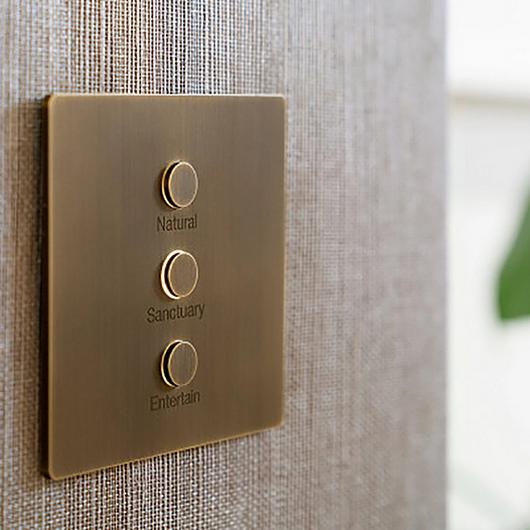
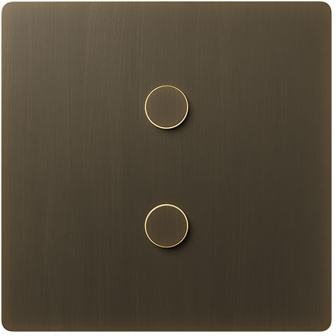
Alisse Keypad
Installation Instructions
HomeWorks
- HW-NW-KP-S1
- HW-NW-KP-S1-E
- HW-NW-KP-S2
- HW-NW-KP-S2-E
- HW-NW-KP-S3
- HW-NW-KP-S3-E
Included Components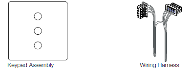
Use these instructions to install the model numbers listed above.
Important Notes
Install in accordance with all national and local electrical codes. Lutron recommends that wall stations be installed by a qualified electrician. Do not connect high-voltage power to low-voltage terminals. Improper wiring can result in personal injury or damage to the control or to other equipment.Environment: Ambient operating temperature: 32 °F to 104 °F (0 °C to 40 °C), 0% to 90% humidity, non-condensing. Indoor use only.Cleaning: For disinfecting keypad, please refer to app note: http://www.lutron.com/TechnicalDocumentLibrary/048758_Cleaning_Recommendations_for_Lutron_Products.pdfBackboxes:Square-style backbox dimensions: 2.95 in H × 2.95 in W × ≥ 1.4 in D (75 mm H × 75 mm W × ≥ 35 mm D)Round-style backbox dimensions: f 2.68 in × ≥ 1.4 in D (f 68 mm × ≥ 35 mm D)
Base Unit Wiring
- The total length of wire on a wired QS link is not to exceed 2000 ft (610 m).
- Wiring may be in a daisy-chain, star, or T-tap configuration.
- See 041799 for reference.
System Programming: Programming and activation (addressing) must be accomplished through the system software.Engraving: Engraving must be specified when ordering the keypad. See engraving.lutron.com/alisse for engraving details.
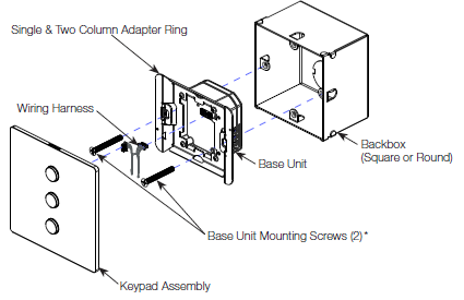
Installation
- WARNING — Shock Hazard. May result in Serious Injury or Death. Turn off power at the circuit breaker before installing the unit.Single Column
 Two Column Three Column
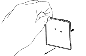
 - Remove the construction cover from the base unit (if present) by pulling from the corner.
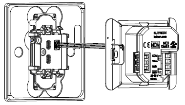
- Connect the keypad to the base unit.
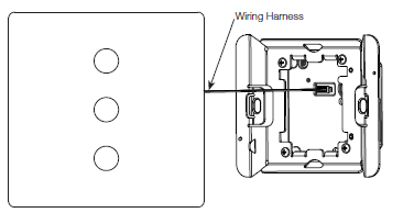
- Connect one end of the wiring harness (provided with the keypad) to the base unit.
- Connect the other end of the wiring harness to the keypad.Keypad to Base Unit Wiring
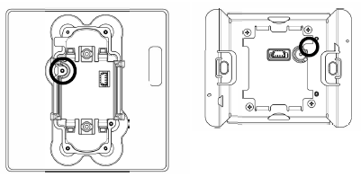
- Snap the keypad assembly onto the base unit, aligning the features shown below in the keypad and the base unit. Do not pinch the wires.
- Turn on the power.
 Two Column
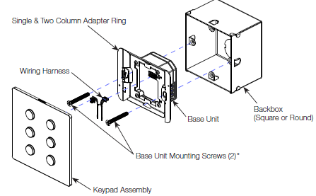 Three Column
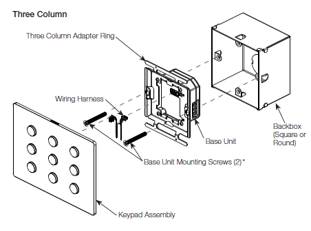
Troubleshooting Guide
| Symptom | Possible Causes |
| Keypad LEDs do not change when the button is pressed. | • Miswire or loose connection of the keypad to the base unit harness.
• Device programmed incorrectly. |
| Keypad LEDs do not turn on. | • Miswire or loose connection of the keypad to the base unit harness.
• Keypad damaged and not turning on. |
| Keypad LEDs scrolling upward. | • Miswire or loose connection at the wired QS link. |
| CCIs do not function as intended. | • Miswire or loose connection at the wired CCI link.
• Device programmed incorrectly. |
| Base unit button does not function as intended. | • No loads connected to the same link as the base unit. (Prior to programming, only loads on the same link as the base unit will toggle on / off.)
• Device programmed incorrectly. • No communication with the QS processor. |
| Base unit LED flashing Green. | • Device working properly. |
| Base unit LED flashing Blue. | • Device receiving updates from the QS processor. |
| Base unit LED flashing Red. | • No communication with the QS processor. |
| Keypad does not sit flush to the wall surface. | • Wrong adapter for backbox shape. |
| Keypad won’t snap onto adapter. | • Adapter mounted upside down, ensure adapter and keypad alignment features correctly align. See Step 3 for reference.
• Incorrect adapter for the backbox shape used. • Incorrect adapter for the number of keypad columns. |
Returning Keypads to Factory SettingsReturning a keypad or base unit to its Factory Settings will remove the keypad and base unit from the system and erase all programming.
- Triple tap any button on the keypad or the base unit button. DO NOT release after third tap.
- Keep the button pressed on the third tap until all the LEDs start to flash slowly (approximately 3 seconds).
- Immediately release the button and triple tap the button again. The LEDs on the keypad and the base unit will flash quickly. The keypad has now been returned to Factory Settings.
Warranty:http://www.lutron.com/TechnicalDocumentLibrary/043492.pdfhttps://www.lutron.com/TechnicalDocumentLibrary/Intl_Warranty.pdf
Note: Contact your local Lutron representative for replacement parts
Replacement AdaptersNW-A-S1 (Square backbox single & two column adapter)NW-A-S3 (Square backbox three column adapter)NW-A-R1 (Round backbox single & two column adapter)NW-A-R3 (Round backbox three column adapter)
Replacement Wiring HarnessNW-WIH
FCC/IC InformationPlease visit www.lutron.com/FCC![]()
[xyz-ips snippet=”download-snippet”]