
Alisse QS Keypad Base Unit Installation Guide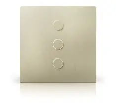
Included Components
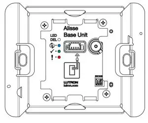
- Base Unit with Adapter

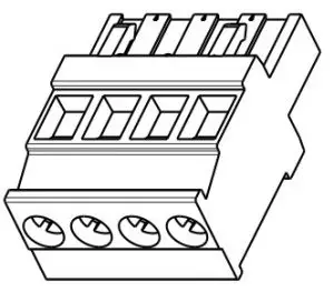
- QS Connector
- Construction Cover
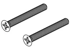
- Mounting Screws(HW-QS-B-S1 andHW-QS-B-S3 only)

Use these instructions to install the model numbers listed above
Important Notes
Install in accordance with all national and local electrical codes.
Lutron recommends that wallstations be installed by a qualified electrician.
Do not connect high-voltage power to low-voltage terminals. Improper wiring can result in personal injury or damage to the control or to other equipment.
Environment: Ambient operating temperature: 32 °F to 104 °F(0 °C to 40 °C), 0% to 90% humidity, non-condensing. Indoor use only
Cleaning: To clean, wipe with a clean damp cloth. DO NOT use any chemical cleaning solutions.
Backboxes:Square-style backbox dimensions: 2.95 in H × 2.95 in W × ≥ 1.4 in D(75 mm H × 75 mm W × ≥ 35 mm D)
Round-style backbox dimensions: f 2.68 in × ≥ 1.4 in D(68 mm × ≥ 35 mm D)
Square backboxes with no flanges must be installed with the box sides flushwith or slightly inset to the wall surface. Round or square boxes with flangesmust be installed with the flange flush to the wall surface.
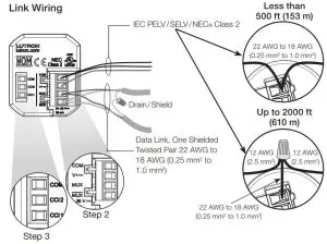
Keypad Wiring
- The total length of wire on a wired QS link is not to exceed 2000 ft (610 m).
- Wiring may be in a daisy-chain, star, or T-tap configuration.
System Programming: Programming and activation (addressing) must be accomplished through the system software.
Adapter Replacement: Adapters are specific to backbox shape and number of keypad columns. Be sure to select the correct adapter for your installation. Please review the spec submittal http://www.lutron.com/TechnicalDocumentLibrary/3691154.pdf for further detail.
Installation
- WARNING — Shock Hazard. May result in Serious Injury or Death. Turn off power at the circuit breaker before installing the unit.
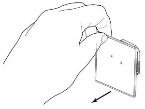
- .Remove the construction cover by pulling from the corner.
- Connect to the wired QS link.
- Strip insulation 3/8 in (10 mm).
- Unplug keypad terminal block from the back of the keypad.
- Connect wiring to the terminal block as shown.
- Plug the keypad terminal block back into the keypad.
- Connect the Contact Closure Input (if applicable)
- Strip insulation 3/8 in (10 mm).
- Connect wiring to the terminal block as shown.
- Torque screws to 3.5 in-lbs (0.40 N•m).
- Push all wires into the backbox and secure using mounting screws.Do not pinch the wires.Square BackboxNote the orientation of the screwsRound BackboxUse screws provided with the backbox. Note the orientation of the screws.
- Turn on the power.
- . Pressing the button prior to programming will toggle on/off other unprogrammed devices on the wired QS link. Button may be programmed through the HomeWorks system for additional functionality.
- Replace the construction cover.
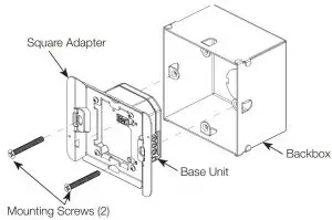
 Use screws provided with the backbox. Note the orientation of the screws.
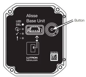

Adapter to Base Unit Assembly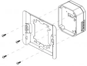
Troubleshooting Guide
| Symptom | Possible Causes |
| Base unit LED flashing Red. |
|
| Base unit LED flashing Blue. |
|
| Base unit LED flashing Green. |
|
| Base unit button does not function as intended. |
|
| CCIs do not function as intended. |
|
| Keypad LEDs scrolling upward. |
|
| Keypad LEDs do not turn on. |
|
| Keypad LEDs do not change when the button is pressed. |
|
| Keypad does not sit flush to the wall surface. |
|
| Keypad won’t snap onto adapter. |
|
Returning Keypads to Factory Settings
Returning a keypad or base unit to its Factory Settings will remove the keypad and base unit from the system and erase all programming.
- Triple tap any button on the keypad or the base unit button. DO NOT release after third tap.
- Keep the button pressed on the third tap until all the LEDs start to flash slowly (approximately 3 seconds).
- Immediately release the button and triple tap the button again.The LEDs on the keypad and the base unit will flash quickly.
The keypad has now been returned to Factory Settings.
Limited Warranty:http://www.lutron.com/TechnicalDocumentLibrary/043492.pdfhttps://www.lutron.com/TechnicalDocumentLibrary/Intl_Warranty.pdf
Note: Contact your local Lutron representative for replacement parts
Replacement Adapters
- NW-A-S1 (Square backbox single & two column adapter)
- NW-A-S3 (Square backbox three column adapter)
- NW-A-R1 (Round backbox single & two column adapter)
- NW-A-R3 (Round backbox three column adapter)
Replacement QS ConnectorNW-CONBase Unit with AdapterMounting Screws(HW-QS-B-S1 andHW-QS-B-S3 only)QS ConnectorAdapter to Base Unit AssemblyFCC/IC InformationPlease visit www.lutron.com/FCC

[xyz-ips snippet=”download-snippet”]