
LCN 4040 Super Smooth Flexible Heavy Duty Closer User Manual

- Standard 4040 series closer shipped with regular arm, standard plastic cover, and self reaming and tapping screws. See 4040 Series pages 45-47 for options.
- Non-sized cylinder is adjustable for interior doors to 5’0” and exterior doors to 4’0”.
- Closer mounts hinge side, top jamb, and parallel arm w/PA Shoe on either right or left swinging doors.
- Closers to meet ADA requirements. See 4040 Series page 48.
- Standard or optional custom powder coat finish.
- Optional plated finish on cover, arm, and fasteners.
- Optional SRI primer for installations in corrosive conditions.
- Optional designer series metal cover
- UL and cUL listed for self-closing doors without hold-open.
- Tested and certified under ANSI Standard A156.4, grade one
FEATURES
The 4040 SUPER SMOOTHEE® is LCN’s most flexible heavy duty closer designed for institutional and other rugged high traffic applications.
- Ten Million Cycles
- Cast Iron
- Forged Steel Arm
- Double Heat Treated Steel Pinion
- All Weather Fluid
- Non-Handed
- LCN® Fast™ Power Adjust
- Fast & Accurate Installation
- UL & cUL Listed

- NEW 4040XP closer shipped with EDA arm, standard plastic cover, and self reaming and tapping screws.
- Non-sized cylinder is adjustable for interior doors to 5’0” and exterior doors to 4’0”.
- Closer mounts parallel arm (EDA arm) on either right or left swinging doors.
- Optional hinge side and top jamb mount with optional regular arm.
- Closers to meet ADA requirements. See 4040XP Series page 49.
- Standard or optional custom powder coat finish.
- Optional plated finish on metal cover, arm and fasteners.
- Optional SRI primer for installations in corrosive conditions is available with powder coat only.
- Optional designer series metal cover
- UL and cUL listed for self-closing doors without hold-open.
- 4040XP can be used with all 4041 accessories. See pages 45-47 for options.
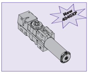
New 4040XP
The new 4040XP is LCN’s most durable heavy duty closer designed for the most demanding, high use and abuse applications.
- 44% increased bearing load capacity
- Strongest pinion ever- at 3/4” journal diameter
- Widest bearing ever- at 5/8”
- Stronger pinion teeth
- New V-shield™ seal with 20% longer life
- XP = eXtra Protection in real world applications
- Cast Iron
- Forged Steel Arm
- Double Heat Treated Steel Pinion
- All Weather Fluid
- Non-Handed
- LCN® Fast™ Power Adjust
- Fast & Accurate Installation
- UL & cUL Listed
- Tested and certified under ANSI Standard A156.4, grade one
MOUNTING DETAILS
HINGE (PULL) SIDE MOUNTING
MAXIMUM OPENING
Templating allows up to 120°.
Hold-open points 90° up to 120° with hold-open arm.
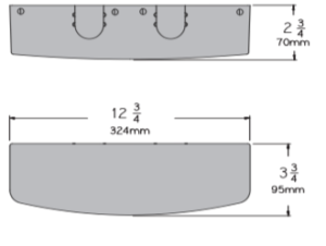
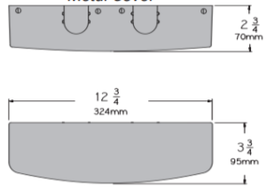
Optional, Non-handed Designer Series Metal Cover
Options
- 4040XP cylinder
- 4041 Delayed action cylinder.
- Hold-open arm.
- Metal or lead lined cover.
- Corner bracket.
- Designer Series metal cover.
Special TemplatesCustomized installation templates or products may be available to solve unusual applications. Contact LCN for assistance.
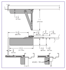
- Butt Hinges should not exceed 5” (127 mm) in width.
- Auxiliary Stop is recommended at hold-open point or where a door cannot swing beyond 120°.
- Reveal should not exceed 3/4” (19 mm) for regular arm or hold-open arm.
- Top Rail less than 3 3/4” (95 mm) requires PLATE, 4040-18. Plate requires 2” (51 mm) minimum. With Designer Series metal cover, use PLATE, 4040-18DS1
- Clearance of 2 3/8” (60 mm) behind door required for 90° installation. 2 7/8” (73 mm) for Designer Series metal covers
- Delayed Action (not available on 4040XP) Add suffix “DEL” to selected cylinder (eg. 4041 DEL). Delays closing from 120° to 70°. Delay time adjustable up to approximately 1 minute.
- Bull Nose Trim requires SOFFIT SHOE, 4040-65.
- Corner Bracket available for doors where top jamb or parallel arm mounting can not be used.4040-16 allows 110° opening. Projects 5” (127 mm) from stop, 12 13/16” (325 mm) from frame.4040-17 allows 100° opening with certain auxiliary door holders (consult factory). Projects 6 3/8” (162 mm) from stop, 13 11/16” (348 mm) from frame.
- Butt Hinges should not exceed 5” (127 mm) in width.
- Auxiliary Stop is recommended at hold-open point or where the door cannot swing 120°.
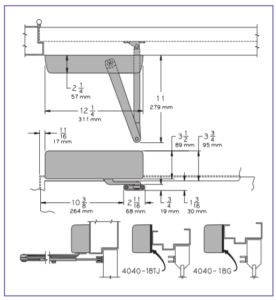
- Reveal of 2 9/16” (65 mm) allows 120° opening for REGULAR ARM or standard HOLD-OPEN ARM. 4 13/16” (122 mm) allows up to 120° opening with LONG ARM where standard rod and shoe is replaced with optional LONG ROD AND SHOE 4040-79LR. Use H-LONG ARM with LONG HEAD AND TUBE, 4040 78HL for hold-open. 8” (203 mm) allows up to 120° opening with EXTRA LONG ARM where standard rod and shoe is replaced with optional EXTRA LONG ROD AND SHOE, 4040-79ELR.
- Top Rail requires 1 1/4″ (32 mm) minimum.2 1/4″ (57 mm) minimum with closer on PLATE, 4040-18TJ.3″ (76 mm) minimum with closer on PLATE, 4040-18G. With Designer Series metal cover, use PLATE, 4040-18TJDS1
- Head Frame less than 3 1/2” (89 mm) requires PLATE, 4040-18TJ.With flush ceiling, use PLATE, 4040-18G.Either plate requires 1 3/4” (44 mm) minimum.
- Delayed Action (not available on 4040XP) Add suffix “DEL” to selected cylinder (eg. 4041 DEL). Delays closing from 120° to 80°. Delay time adjustable up to approximately 1 minute.
TOP JAMB (PUSH SIDE) MOUNTING
MAXIMUM OPENING
Templating allows up to 120°.
Hold-open points 85° up to 120° with hold-open arm.
Optional, Non-handed Designer Series Metal Cover
Options
- 4040XP cylinder
- 4041Delayed action cylinder.
- Long arm, extra long arm, hold-open arm, long hold-open arm.
- Metal or lead lined cover.
- Designer Series metal cover.
Special Templates
Customized installation templates or products may be available to solve unusual applications. Contact LCN for assistance
PARALLEL ARM (PUSH SIDE) MOUNTING
Optional mounting requires PA SHOE, 4040-62PA for REGULAR or HOLDOPEN arms. Add prefix “P” to closer description (eg. P4041). P4041 closer includes 4040-201 FIFTH HOLE SPACER to support PA SHOE.
MAXIMUM OPENING
180° opening/hold-open points with all except CUSH arms.
110° opening/hold-open with CUSH arms.
Optional, Non-handed Designer Series Metal Cover
Options
- 4040XP cylinder
- 4041 Delayed action cylinder.
- Hold-open, EDA, HEDA, CUSH, HCUSH, SPRING CUSH, or SPRING HCUSH arm.
- Metal or lead lined cover.
- Designer Series metal cover.
Special TemplatesCustomized installation templates or products may be available to solve unusual applications. Contact LCN for assistance.
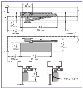
- Butt Hinges should not exceed 5” (127 mm) in width.
- Auxiliary Stop is recommended at hold-open point, where the door cannot swing 180°, or where CUSH-N-STOP arm is not used.
- Clearance for 4040-62PA shoe is 4” (102 mm) from door face.EDA shoe projects 5 1/2” (140 mm) from door face.CUSH shoe projects 6” (152 mm) from door face.
- Top Rail less than 5 3/8” (137 mm) measured from the stop requires PLATE, 4040-18PA. Plate requires 2” (51 mm) minimum from the stop. With Designer Series metal cover, use PLATE, 4040-18PADS1
- Head Frame flush or rabetted requires PA SHOE ADAPTER, 4040-418.
- Stop Width minimum 1” (25 mm). CUSH arm requires minimum 1 1/2” (38 mm).
- Blade Stop clearance requires 1/2″ (13mm) BLADE STOP SPACER, 4040-61.
- Delayed Action (not available on 4040XP) Add suffix “DEL” to selected cylinder (eg. P4041 DEL). Delays time adjustable up to approximately 1 minute.
4040 SERIES EDA MOUNT

4040 SERIES CUSH MOUNT
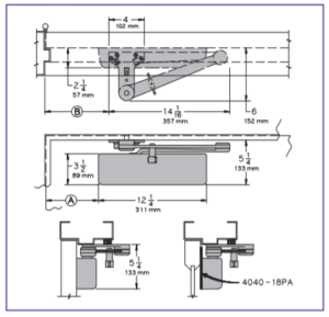
- Clearance for 4040-62EDA is 5 1/2” (140 mm) from door face. 6” (152 mm) for CUSH.
- Head Frame flush or rabetted requires CUSH FLUSH PANEL ADAPTER, 4040-419.
- CUSH ARM requires SHOE SUPPORT, 4040-30 for fifth screw anchorage for narrow frames.
- Delayed Action (not available on 4040XP) Add suffix “DEL” to selected cylinder (eg. 4041 DEL). Delays closing from maximum opening to; 115˚ with 180˚ template.95˚ with 110˚ template. 85˚ with 100˚ template.75˚ with 90˚ template.Delay time adjustable up to approximately 1 minute.
Mounting details are the same as 4040 Series REGULAR or HOLD-OPEN except as listed below.4040 Series closers ordered with EDA or CUSH arms include 4040-201 FIFTH HOLE SPACER to support the shoe.
MAXIMUM OPENING
EDA arm can be templated for points at: 110°,A = 6 3/8” (162 mm)B = 7 3/4” (197 mm)
or 180°.A = 2 7/8” (73 mm)B = 4 1/4” (108 mm)
Hold-open points up to maximum opening with HEDA arm.
CUSH arms can be templated for opening/hold-open point at: 85°,A = 7 15/16” (202 mm)B = 9 1/8” (232 mm)
90°,A = 7 3/16” (183 mm)B = 8 1/2” (216 mm)
100°,A = 6 1/16” (154 mm)B = 7 1/4” (184 mm)
or 110°.A = 5 1/16” (129 mm)B = 6 3/8” (162 mm)
Spring Cush dead stop points are approximately 5˚ more than templated stop point. Hold open at templated stop points.
ACCESSORIES
CYLINDERS
CYLINDER, 4041-3071Standard, non-handed cast iron cylinder assembly.
CYLINDER, 4040XP-3071Heavy duty, non-handed cast iron cylinder assembly.
COVERS
COVER, 4040-72Standard, non-handed plastic cover.
METAL COVER, 4040-72MCOptional, handed cover. Required for plated finishes and custom powder coat finishes.
LEAD LINED COVER, 4040-72LLOptional non-handed plastic cover.
DESIGNER SERIES METAL COVER, 4040-72DS1Optional, non-handed designer series metal cover.
ARMS
REGULAR ARM, 4040-3077Non-handed arm mounts pull side or top jamb with shallow reveal.P4041 closer includes PA SHOE, 4040-62PA required for parallel arm mounting.
PA SHOE, 4040-62PA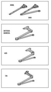 Required for parallel arm mounting.
LONG ARM, 4040-3077LOptional non-handed arm includes LONG ROD AND SHOE, 4040-79LR for top jamb mount.
EXTRA LONG ARM, 4040-3077ELROptional non-handed arm includes EXTRA LONG ROD AND SHOE, 4040-79ELR for top jamb mount with deep reveal.
HOLD-OPEN ARM, 4040-3049Optional, non-handed arm mounts pull side or top jamb with shallow reveal, hold-open adjustable shoe. P4041 closer includes 4040-62PA shoe required for parallel arm mounting.
LONG HOLD-OPEN ARM, 4040-3049LOptional non-handed arm includes LONG HEAD AND TUBE, 4040-3048L for top jamb mount.
EXTRA DUTY ARM, 4040-3077EDANon-handed parallel arm features forged, solid steel main and forearm for potentially abusive installations.
HOLD-OPEN EXTRA DUTY ARM, 4040-3049EDAOptional handed arm provides hold-open function, adjustable at the shoe. 
THICK HUB SHOE, 4040-62GOptional for blade stop clearance, requires special templating.
FLUSH TRANSOM SHOE, 4040-145Optional for single rabetted installations, requires special templating.
CUSH-N-STOP® ARM, 4040-3077CNSOptional, non-handed parallel arm features solid forged steel main arm and forearm with stop in soffit shoe.
HCUSH ARM, 4040-3049CNSProvides hold-open function with templated stop/hold-open points. Handle controls hold-open function.
SPRING CUSH ARM, 4040-3077SCNSOptional, non-handed parallel arm for abusive applications features solid forged steel main arm and forearm with spring loaded stop in the soffit shoe.
SPRING HCUSH ARM, 4040-3049SCNSOptional, non-handed parallel arm for abusive applications features solid forged steel main arm and forearm with spring loaded stop in the soffit shoe. Handle controls hold-open function.
INSTALLATION ACCESSORIES
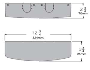
PLATE, 4040-18/4040-18DS1Required for hinge side mount where top rail is less than 3 3/4” (95 mm). Plate requires minimum 2” (51 mm) minimum top rail. With Designer Series metal cover, use PLATE, 4040-18DS1 
PLATE, 4040-18GLocates top jamb mounted closer flush with top of head frame face in flush ceiling condition. Plate requires 1 3/4” (44 mm) minimum head frame.
PLATE, 4040-18TJ/4040-18TJDS1Centers top jamb mounted closer vertically on head frame where face is less than 3 1/2” (89 mm). Plate requires 1 3/4” (44 mm) minimum head frame. With Designer Series metal cover, use PLATE, 4040-18TJDS1
PLATE, 4040-18PA/4040-18PADS1Required for parallel arm mounting where top rail is less than 5 1/2” (140 mm), measured from the stop. Plate requires 2” (51 mm) minimum top rail. With Designer Series metal cover, use PLATE, 4040-18PADS1
CORNER BRACKET, 4040-17Designed to lower closer for clearance of certain auxiliary holders (consult factory). 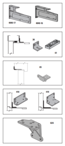
CORNER BRACKET, 4040-16For doors where top jamb or parallel arm mounting cannot be used (consult factory).
CUSH SHOE SUPPORT, 4040-30 provides anchorage for fifth screw used with CUSH arms, where reveal is less than 3 1/16” (78 mm).
BLADE STOP SPACER, 4040-61 required to lower parallel arm shoe to clear 1/2” (13 mm) blade stop.
SOFFIT SHOE, 4040-65 adapts hinge side shoe to rounded or bull nose trim.
PA SHOE ADAPTER, 4040-418 provides horizontal mounting surface for parallel arm shoe on single rabetted or flush frame.
CUSH FLUSH PANEL ADAPTER, 4040-419 provides horizontal mounting surface for CUSH shoe on single rabetted or flush frame.
AUXILIARY SHOE, 4040-62A requires a top rail of 7” (178 mm). Optional shoe replaces -62PA for parallel arm mounting of regular arm with overhead holder/stop.
ORDERING INFORMATION
TABLE OF SIZES
4041 cylinders are adjustable from size 1 through size 6 and is shipped set to size 3.Closing power of 4040 series closers may be adjusted 50%
Indicates recommended range of door width for closer size.

REDUCED OPENING FORCE 4040 SERIES CLOSERS
CAUTION ! Any manual door closer, including those certified by BHMA to conform to ANSI Standard A156.4, that is selected, installed and adjusted based on ADA or other reduced opening force requirements may not provide sufficient power to reliably close and latch a door.
Refer to POWER OPERATORS section for information on systems that meet reduced opening force requirements without effecting closing power.
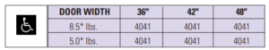
* Maximum opening force
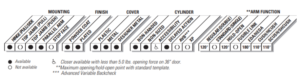
HOW-TO-ORDER 4041 SERIES CLOSERS
1. SELECT FINISH.
- Standard Powder Coat __________Aluminum, Dark Bronze , Tan, Statuary, Light Bronze, Black, Brass.
Closer will be shipped with:– STANDARD COVER,– REGULAR ARM,– SELF-REAMING and TAPPING SCREWS, unless options listed below are selected.
CLOSER OPTIONS
CYLINDER
- Delayed Action (DEL)
COVER
- Lead Lined (LL)
- Metal (specify right or left hand) (MC)
- Designer Series Metal (non-handed) (DS1)
FINISH
- Custom Powder Coat (RAL) ___________ (handed metal cover required)
- Plated Finish, US ______________ (handed metal cover required)
- SRI primer
ARM
- Regular w/62PA (Rw/PA)
- Regular w/62A (R/62A)
- Long (LONG)
- Extra Long (XLONG)
- Hold-Open (H)
- Hold-Open w/62PA (Hw/PA)
- Long Hold-Open (HLONG)
- EDA (optional -62G or -145)
- HEDA (specify right or left hand, optional-62G or -145)
- Cush-N-Stop (CUSH)
- HCush-N-Stop (HCUSH)
- Spring Cush (SCUSH)
- Spring HCush (SHCUSH)
OPTIONAL SCREW PACKS
- TB* w/Self-Reaming and Tapping (TBSRT)
- Wood & Machine Screw (WMS)
- TB*, Wood & Machine Screw (TBWMS)
- TORX Machine Screw (TORX)
- TB* & TORX Machine Screw (TBTRX)
* Specify door thickness if other than 1 3/4”.
INSTALLATION ACCESSORIES
- Plate, 4040-18
- Plate, 4040-18TJ
- Plate, 4040-18G
- Plate, 4040-18PA
- Plate, 4040-18DS1
- Plate, 4040-18TJDS1
- Plate, 4040-18PADS1
- CUSH Shoe Support, 4040-30
- Blade Stop Spacer, 4040-61
- Auxiliary Shoe, 4040-62A
- Soffit Shoe, 4040-65
- PA Shoe Adapter, 4040-418
CUSH Flush Panel Adapter, 4040-419
SPECIAL TEMPLATE
- ST- ________
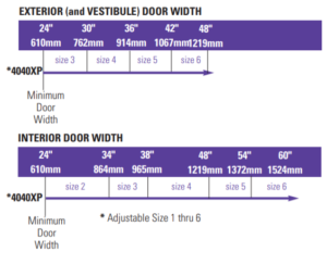
TABLE OF SIZES
4040XP cylinders are adjustable from size 1 through size 6 and is shipped set to size 3.Closing power of 4040 series closers may be adjusted 50%.
Indicates recommended range of door width for closer size.
REDUCED OPENING FORCE 4040 SERIES CLOSERS
CAUTION ! Any manual door closer, including those certified by BHMA to conform to ANSI Standard A156.4, that is selected, installed and adjusted based on ADA or other reduced opening force requirements may not provide sufficient power to reliably close and latch a door.
Refer to POWER OPERATORS section for information on systems that meet reduced opening force requirements without effecting closing power.

* Maximum opening force
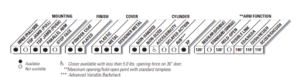
HOW-TO-ORDER 4040XP SERIES CLOSERS
1. SELECT FINISH.
Standard Powder Coat __________Aluminum, Dark Bronze , Tan, Statuary, Light Bronze, Black, Brass.
Closer will be shipped with:– STANDARD COVER,– EDA ARM,– SELF-REAMING and TAPPING SCREWS, unless options listed below are selected.
CLOSER OPTIONS
COVER
- Lead Lined (LL)
- Metal (specify right or left hand) (MC)
- Designer Series Metal (non-handed) (DS1)
FINISH
- Custom Powder Coat (RAL) ___________ (handed metal cover required)
- Plated Finish, US ______________ (handed metal cover required)
- SRI primer
ARM
- Regular (Rw)
- Regular w/62PA (Rw/PA)
- Regular w/62A (R/62A)
- Long (LONG)
- Extra Long (XLONG)
- Hold-Open (H)
- Hold-Open w/62PA (Hw/PA)
- Long Hold-Open (HLONG)
- EDA -62G or -145
- HEDA (specify right or left hand, optional-62G or -145)
- Cush-N-Stop (CUSH)
- HCush-N-Stop (HCUSH)
- Spring Cush (SCUSH)
- Spring HCush (SHCUSH)
OPTIONAL SCREW PACKS
- TB* w/Self-Reaming and Tapping (TBSRT)
- Wood & Machine Screw (WMS)
- TB*, Wood & Machine Screw (TBWMS)
- TORX Machine Screw (TORX)
- TB* & TORX Machine Screw (TBTRX)
* Specify door thickness if other than 1 3/4”.
INSTALLATION ACCESSORIES
- Plate, 4040-18
- Plate, 4040-18TJ
- Plate, 4040-18G
- Plate, 4040-18PA
- Plate, 4040-18DS1
- Plate, 4040-18TJDS1
- Plate, 4040-18PADS1
- CUSH Shoe Support, 4040-30
- Blade Stop Spacer, 4040-61
- Auxiliary Shoe, 4040-62A
- Soffit Shoe, 4040-65
- PA Shoe Adapter, 4040-418
- CUSH Flush Panel Adapter, 4040-419
SPECIAL TEMPLATE
- ST- ________
LCN 4040 Super Smooth Flexible Heavy Duty Closer User Manual – LCN 4040 Super Smooth Flexible Heavy Duty Closer User Manual –