
AllegionLCN Benchmark® AU9100 SeriesLow Energy OperatorsInstallation Manual
LCN Low Energy Operators should be installed in accordance with the current Allegion LCN installation instructions.
Commissioning and Servicing of installed units must be carried out by an Allegion Approved, Authorised Technician
1 GENERAL
The LCN Benchmark® 9100 Series is an automatic electromechanical swing door operator for use on hinged, centre pivoted, and offset pivoted doors. The controller is a microprocessor based system, tracking the door position at any time during the cycle. When activated the Benchmark® 9100 drives the door to the full open position creating the potential energy in the spring. When closing the electrical power is reduced and the door closes by controlling the potential energy release in the spring force. The activating circuit opens the door from any position on the closing swing. During power failure the Benchmark® 9100 acts as a manual door closer (size 3). Door opening and closing cycles, including opening speed, back check speed, hold open time delay, closing speed, and latch position are all adjustable.
WARNING! Always disconnect main power to the operator prior to servicing or cleaning
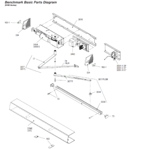
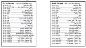
2 REPLACEMENT PARTS AND SYSTEM COMPONENTS
3 PRE-INSTALLATION SITE AND PRODUCT CHECK
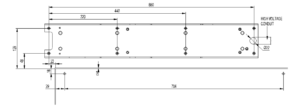
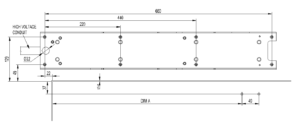
3.1 Check that the product model is correct for the required application3.2 Check that all parts listed for the installation are received3.3 Check architectural drawings and final approved shop drawings for position of frame and structural openings3.4 Check header and frame dimensions and required clearances
![]()
3.5 Ensure door weight is less than 90Kgs. For heavier doors consult supplier3.6 Check that a 240 Volt, single phase, 60 Hz, fused supply (5 amp fuse maximum) is available at the side of the jamb within approximately 1 Meter of the header. Approved type conduit is recommended for 240V systems3.7 If an electric lock is to be connected to the system, the maximum current draw is 2 Amps. The switching relay contact is a maximum resistive current of 2 Amps.3.8 The supply must be a dedicated circuit from the main circuit breaker panel and must not be connected into building lighting circuit with fluorescent lights
4 OPERATOR INSTALLATION
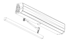
4.1 Remove control box from mounting bracket, then remove Motor/Gearbox from bracket
4.1 Remove control box from mounting bracket, then remove Motor/Gearbox from bracket4.2 Prepare header frame Pull system …………………See Page 5Push system…………………See Page 6
NOTEFor push units with a reveal greater than 150 mm refer to installation sheet included in the extended arm Packaging.
4.3 Install operator-mounting bracket on the header/frame.4.4 Install motor/gearbox on operator mounting bracket, then install control box on bracket Go to wiring page 7
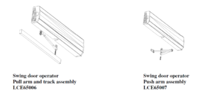
Pull SystemFramed Header and Door Preparation

5 WIRING
CAUTION
- Make sure all wires are properly dressed and secured to prevent interference
- Route all wiring away from moving parts, sharp edges, and heat sources
- Use copper conductors only
- Do not modify the factory wiring or connect into existing electrical circuits or devices
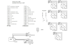
5.1 Refer to the appropriate wiring diagram for the standard control box (Page 22) or the diagram supplied for custom applications. And connect the following cables
- Ground cable (Ground the operator properly with the earth from main supply
- Hall effect Cable (do not wrap the hall effect cable around the motor cable)
- Motor power cable (do not wrap the motor cable around the hall effect cable)
- Control box power cable
5.2 Connect Activate, Safety, Key switch, and lock accessories as needed. Refer to the accessory instruction/s for any accessories used. Do not connect any remote activating device to the door unless it is located within line of sight of the door5.3 When wiring is complete go to “Arm and cover installation” on page 8
6 ARM AND COVER INSTALLATION
WARNING
- Keep hands, clothing, wires, tools, ETC away from the operator motor when the operator is turned on
6.1 Make sure the operator power switch is turned OFF6.2 Install a jumper across the control box MAIN ACT T28 and COMMON T276.3 Turn the operator power switch on. The operator motor will activate and drive to the full open position.6.4 Attach the arm to the operator spindle loosely with the 8-mm socket head screw (for push systems ensure adjusting boss is inserted correctly).
6.5 Attach the arm to the door6.5.1 For push systems attach the push arm shoe to the door
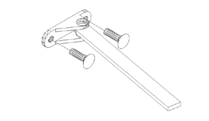
6.5.2 For pull systems, slide the pull arm roller into the track, insert a track cap on each end of the track, and attach the track to the door.
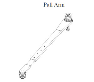
6.6 Adjust the arm6.6.1 For pull systems, remove the locking screw from the arm6.6.2 For the push system remove the locking screw from the arm

6.7 Keep the door in the full open position and adjust the arm length as necessary to align the door at 90 degrees from closed. When the arm is adjusted to the correct length, tighten up the 8mm socket head screw that secures the arm to the operator spindle and ensure this is secure, then tighten the arm locking screw6.8 Turn off the power operator switch. The door closes6.9 Remove the jumper from the control box T27, T286.10 Test the operator (See operational check” on page 11) and continue with step 6. 106.11 Adjust the operator as required( see “Operator Adjustment” on page 12) and continue with step6.12 Snap optional end cap insert (from screw bag) into the end cap opposite the on/off switch.6.13 Install the cover assembly on the operator6.14 Release the operator for service ( see “Release for Service” on page 14)
7 OPERATIONAL CHECK
7.1 Set the Key switch to Auto (1 Way) and turn on the operator power switch7.2 Activate the operator using the activation device, the operator will perform one sizing cycleSizing cycle: Occurs after a legitimate activation signal is received, after power has been turned on. During the size cycle, the door opens and closes one time.7.2.1 If the door does not open at all during sizing cycle7.2.2 Check door for binding7.2.3 If an electromechanical lock is being used, check that the lock disengages before the operator opens the door.7.2.4 Check fuses, Circuit breakers, and connections.7.2.5 Adjust the operator and check door operation (See “Operator Adjustment on page xx)
Opening speed 75%Back check speed 75%Hold open time delay MinimumLatch position MaximumClosing speed 50%SW1, 2, 3, 4 OFF
If the door does not open fully during size cycle check the door for binds
Increase the back check speed slightly and check door operation continue increasing back check speed until door opens fully
7.3 If the door slams open decrease the back check speed slightly and check door operation. Continue decreasing back check speed until the door opens without slamming7.4 After the sizing cycle is complete and the door is closed, apply a maintained activation signal and check that the door remains open while the signal is applied.7.5 If a door safety device is being used:7.6 Door open safetyWhen the door is in the closed position activate the safety device, then try to activate the door the door should remain closed.Activate the door, as the door is opening activate the safety device the door should stop, and then slowly drive to the full open position.7.7 Door close safetyActivate the door then maintain activation of the safety device, the door should open and remain open.As the door is closing, activate the safety device, the door should re-open to the open position, time out and then close.7.8 When the door is operating properly, continue with step 6.10 on page 9
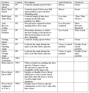
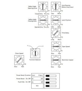
8 OPERATOR ADJUSTMENT
See table below and diagrams on page 18 for operator feature adjustment. After adjustment, cycle the doorseveral times and check for proper operation, then continue with step 6.11 on page 9.
NOTEAdjust operator for the slowest operation practical in accordance with the latest AS_5007 standards for powered doors for pedestrian access and egress.
Opening speed 5 sec’s or more
Closing speed 3 sec’s or more
9 RELEASE FOR SERVICE
9.1 Remove all tools, installation equipment, and debris from the vicinity of the door.9.2 Install all safety, traffic control, and instruction labels on the door as required by the latest AS_5007 Standard. Failure to do this leaves the installer LIABLE for any accident that might occur. This must be done.9.3 Verbally instruct the owner or person in charge of the proper operation of the door.9.4 Instruct the owner or person in charge to routinely inspect the door for the following
- Occasional damage
- Developing problems
- Minor preventative maintenance
9.5 Instruct the owner or people in charge who and where to call for service and maintenance when required.
IMPORTANTMake sure to install all safety, traffic control and instruction decals on the door as required
10 LCN AU9100 (Briton 2500) V4 SOFTWARE
10.1 OPERATION
10.1.1 Sizing
From start up (size) the door will activate from morning entry (24Hrs,T9, T10) regardless of key switch position, 1 Way input (T27,T28) with key switch in one way. 2 Way input (22, T23) with key switch in two way, or key switch Hold Open. The first movement will be in the open direction – The speed of the sizing cycle is automatic and cannot be set from a potentiometer the door drives opened to the full open position where the system sets the counter to full open. The door closes at close speed then latch up to closed position where the system sets the counter for closed position. From these two parameters opened and closed position the system calculates all the other parameters it requires for normal operation i.e. latch position back check position etc.
- NotesIf the encoder is connected for opposite direction or faulty or disconnected the door will operate erratically continuously opening ½ way closing latching and re-opening. This will continue to occur until power is switched off
10.1.2 Auto Reverse on open
The auto reverse open is set from the backcheck position pot. This sets the level of current required to trip the door as it is opening.
Normal operationKey switch, activation, morning entry/fire alarm, locking, and safety.
10.1.3 Standard operation
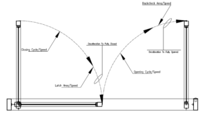
Upon a legitimate activation signal the door accelerates up to open speed, monitoring the current load on the drive output. (If the current reaches a level above the set datum the door will stop and close). The door travels at the set speed (Potentiometer setting) until it reaches the set backcheck position, where the speed (Potentiometer setting) is decreased to back check speed. When the door stops at hold open position the system sets the hold open speed and holds the door open until activation and or timer is cleared. The door will then close at close speed, (Potentiometer setting) up to latch position (Potentiometer setting). Where the speed is decreased by driving the motor in the open direction (fixed setting), the power is set such that the spring will overcome this power and continue to allow the door to close up to the closed position. During the open cycle the safe opening (T1, T2) is active and the Safety side Adj Pot sets the angle at which the sensor is redundant, this can be set from Closed up to back check position. During the closing cycle the safe closing (T5, T6) is active and the Activate side Adj pot sets the angle the sensor is redundant, this can be set from Opened up to a few degrees of closed position.
General24Hr operates the door regardless of key switch position the door will drive open and remain in the open position as long as the contact is made (Program 4 is the exception) Key switch position OFF no activation or safety operates. Electric lock operates when door closed dependant upon function selection Electric lock operation is set from the function selector the time delay is fixed Key switch Position 1 Way the activation from internal Activate (T27, T28) safety operates. Electric lock operates when door closed dependant upon function selection Key switch Position 2 way the activation from internal Activate (T27, T28) and external Activation (T22, T23) safety operates. Electric lock does not operate when door closed Key Switch H.O The door operates to the open position and remains in the open position safety is by passed (If safety activated the door will open slowly)
10.2 FUNCTION SELECTION
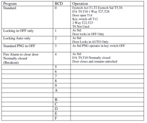
10.2.1 Standard (0)
Operates as a standard door with electric lock operating in OFF and 1 WAY
- Eyetech Activation T5, T6 (Closing Cycle)
- Eyetech Safety T1, T2 (Opening Cycle)
- F/A T9, T10
- 1 Way T27, T28
- 2 Way T22, T23
- Door open T14
- Key switch off T12
- T8 Not Used
10.2.2 Lock in OFF Only (1)
Operates as a standard door with electric lock operating in OFF only.This selection will give a fast activation in Auto or 1 Way from closed as there is no delay for lock operation.
10.2.3 Lock in 1 Way Only (2)
Operates as a standard door with electric lock operating in 1 Way only
10.2.4 PNG in OFF (3)
Operates as a standard with Push & Go operating in key switch OFF
10.2.5 Door closes and Unlocks in Fire Alarm (4)
Operates as a standard Fire Alarm Normally closed if open circuit door closes and will remain Unlocked
10.3 FUNCTION CHART
10.4 CONTROL BOX SETUP
10.5 LCN AU9100 (Briton 2500) ii WIRING
10.6 LCN AU9100 (Briton 2500) ii Terminal Block

LCN AU9100 Series Low Energy Operators User Manual – LCN AU9100 Series Low Energy Operators User Manual –