
LP150, LP250 LP150B, LP250B LP250RDB4
Power Supply
Installation Instructions
The LP150/LP250 is a power-limited power supply and battery charger that will convert 120 VAC / 60Hz input into field-selectable 12 VDC or 24 VDC Class 2 rated outputs (one continuous, one switchable). It is intended for use in applications with UL listing requirements (see specifications below for specific listings).
This instruction covers:
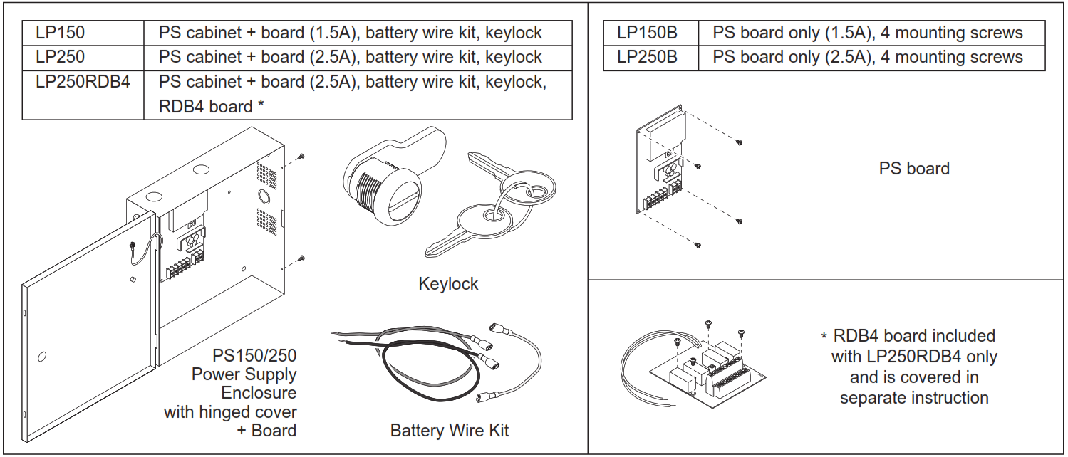
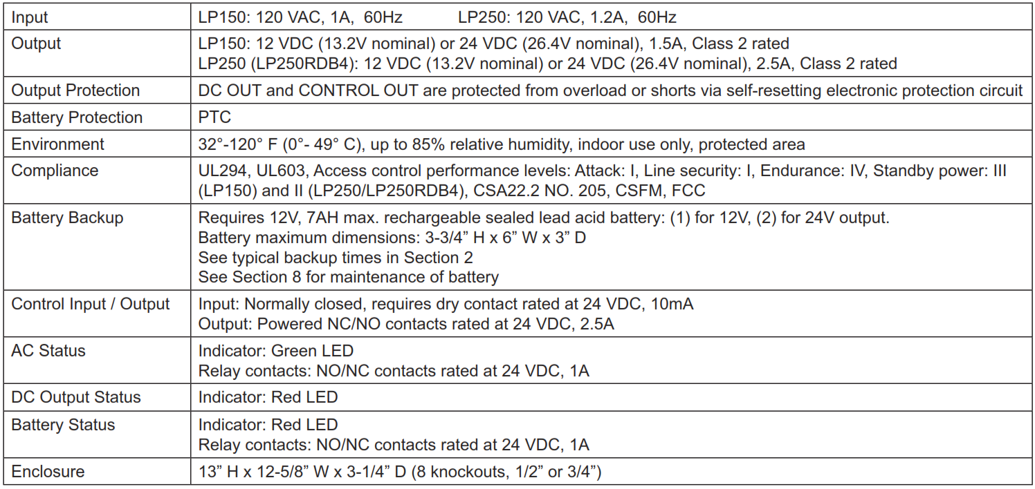
PS150/250 Specifications:
Definitions:
1 Installation Overview
Wiring methods shall be applied in accordance with the National Electric Code/NFPA 70/NFPA 72/ANSI, and with all local codes and authorities having jurisdiction.
![]() WARNINGTo avoid risk of electric shock, turn off AC power before installing or servicing LP150/LP250 power supply.
WARNINGTo avoid risk of electric shock, turn off AC power before installing or servicing LP150/LP250 power supply.
- Mount unit in a protected area per Section 2.
- Select voltage (12 or 24 VDC) per Section 3.
- Connect AC power per Section 3.• Connect the earth ground to the green/yellow cabinet wire and line (L) and neutral (N) to the appropriate terminals on the AC terminal block.
̢ Measure output voltage before connecting devices to prevent damage.
- Disconnect AC power and finish all wiring per Sections 4 and 6.
- Install battery backup (if required) per Sections 2 and 3.
̢ If AC input goes off and battery backup is not being used, all devices connected to the power supply will be unpowered.
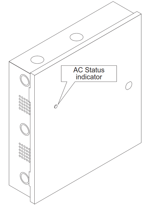
- AC status may be required for Battery Backup systems (Section 3).
- Secure cover with screws or keylock when complete per Section 7.
- For maintenance and troubleshooting, see Sections 8 and 9.
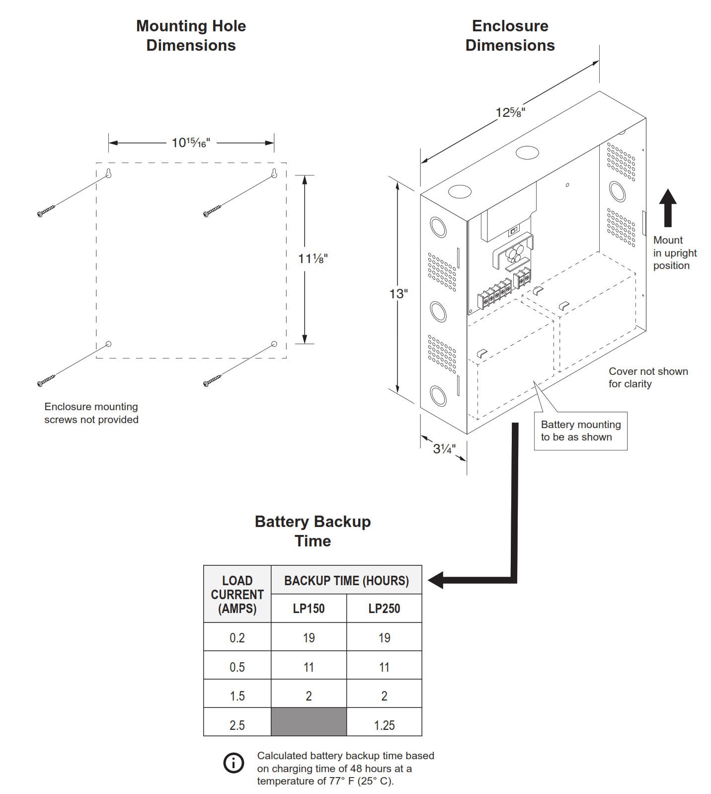
2 Mounting
 CAUTIONProduct intended for indoor use only and within the temperature range specified. Mount unit in a protected area. Do not install in locations with exposure to rain or water.
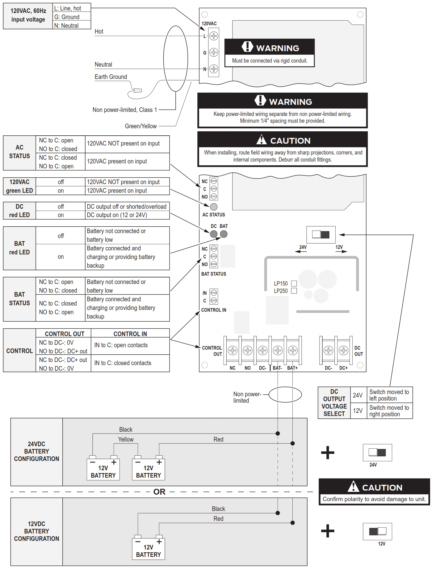
3 Power Supply Board - Features and Operation
4 Typical Wiring
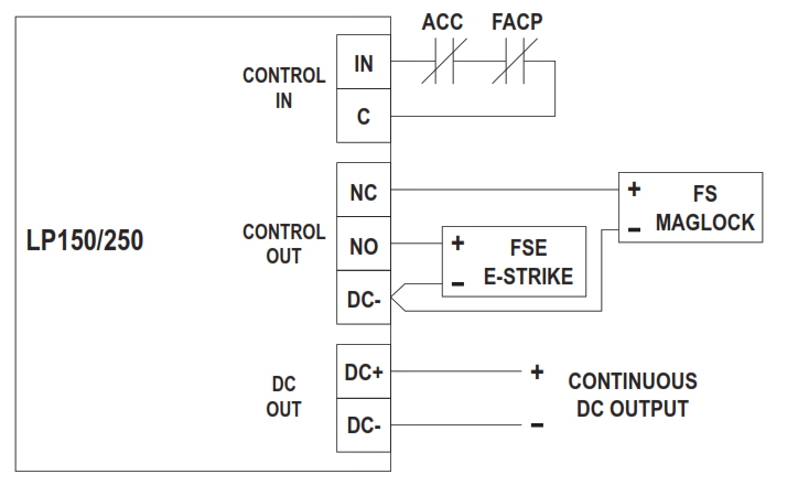
FS & FSE device connected to PS board with FACP override
Operation:
-
-
-
-
-
-
- CONTROL IN controls the operation of devices connected to the NO or NC terminals.
- Opening of the FACP contacts will unpower the CONTROL OUT NC contacts and power the NO contacts.
- DC OUT is always powered regardless of the state of the FACP contacts.
-
-
-
-
-
FSE device using open input control contacts
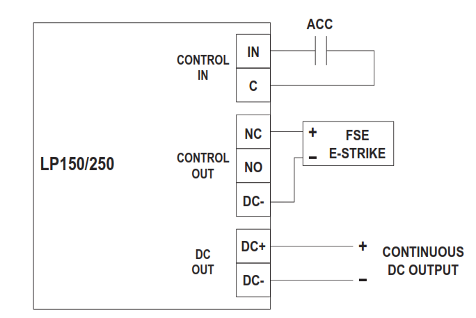
Operation:1. CONTROL IN controls the operation of the strike connected to the NC terminal.2. Closing the ACC contacts will apply power to the FSE strike to unlock it.
5 PS150B and PS250B Installation

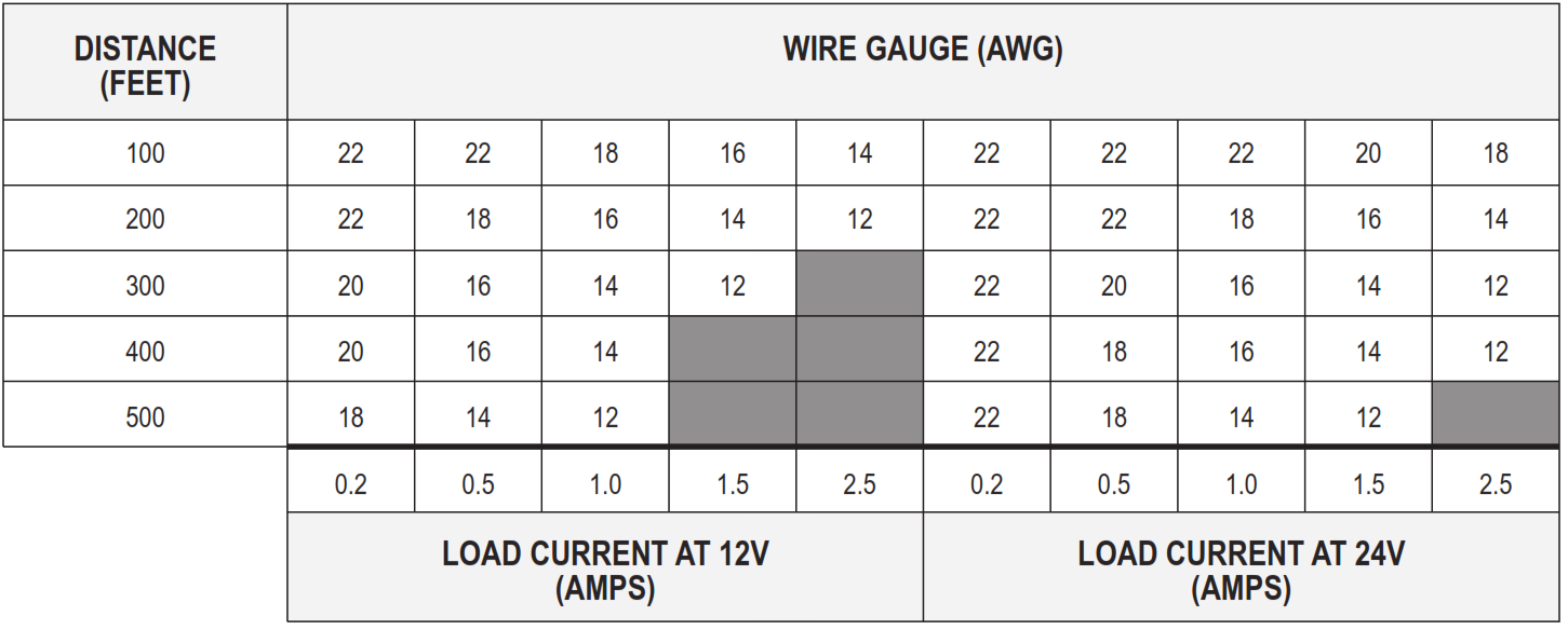
6 Wire run lengths
• Use the following table to estimate the gauge of wire required for the application.• Wire length based on 15% voltage drop at 12 or 24V using stranded copper wire.• The wire gauge listed is a minimum. The gauge can be increased if desired.• Distance = total one-way wiring distance between the power supply and powered device (includes both power wires).• For UL installations, the minimum permissible wire size to be used shall not be less than 22AWG.
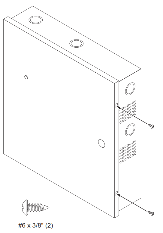
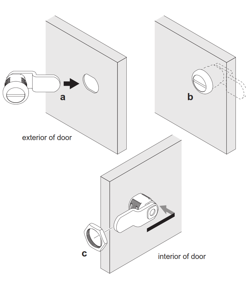
7 Secure enclosure door
If No KeylockEnclosure will be secured with 2 screws as shown (done as last step)
If KeylockRemove knockout and insert key cylinder and secure with nut as shown
8 Maintenance
Unit should be tested at least once a year for proper operation as follows:
Voltage Output:
- Verify the proper DC output voltage by measuring the DC+ and DC- terminals.
Fire Alarm Release (if used):
- Verify proper operation by opening the wiring to the CONTROL IN input. Confirm that the locks controlled by the CONTROL OUT output unlocked properly.
Battery (if used):
- Verify the proper charge voltage (between 26.3 – 26.5 VDC) on the battery terminals by measuring the BAT+ and BAT-terminals.
- Batteries should be changed every 4 years. Record date of install inside the cabinet to track time of service.
9 Troubleshooting
Refer to Section 3 for LED status of the AC input, DC output, and Battery to determine the cause for any abnormal condition. Each LED has the definition of its ON or OFF state.
10 Warnings and Cautions
Warnings look like this:
![]() WARNINGWarnings indicate potentially hazardous conditions, which if not avoided or corrected, may cause death or serious injury.
WARNINGWarnings indicate potentially hazardous conditions, which if not avoided or corrected, may cause death or serious injury.
Cautions look like this:
CAUTION Cautions indicate potentially hazardous conditions, which if not avoided or corrected, may cause minor or moderate injury. Cautions may also warn against unsafe practices.
Notices look like this:
Notices indicate a condition that may cause equipment or property damage only.
Directions look like this:
Directions identify a step that may or may not apply to your product configuration. It also may direct you to another part of the instruction.
Locknetics LP150/LP250 Instruction Manual – Locknetics LP150/LP250 Instruction Manual –