![]()
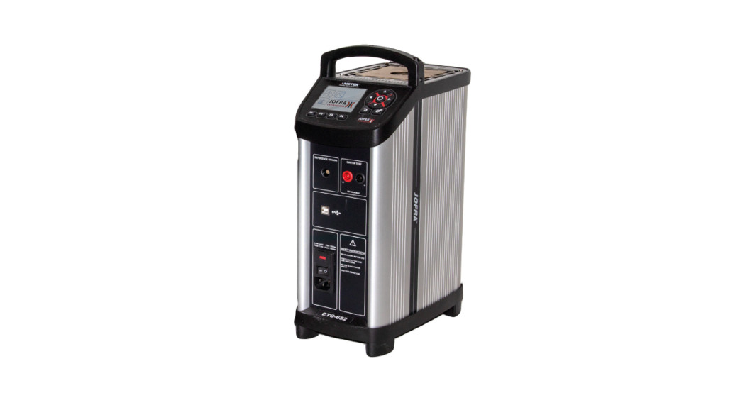
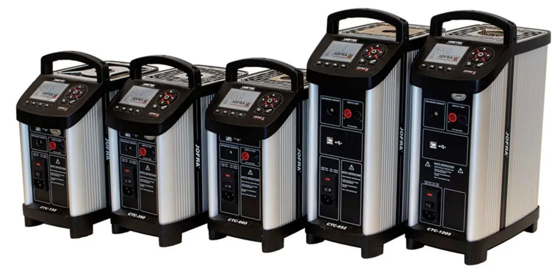
User ManualCompact Temperature CalibratorJofra CTC-155/350/652/660/1205 A/C

Test Equipment Depot – 800.517.8431 – 99 Washington Street Melrose, MA 02176 – TestEquipmentDepot.comCopyright 2016 AMETEK Denmark NS
Introduction
CTC-calibrators are temperature calibrators designed to calibrate temperature sensors and temperature switches.Read this manual carefully before using the instrument and make sure that all safety instructions and warnings are observed.
List of equipment received
When you receive the instrument, the following should be enclosed:
- 1 calibrator
- 1 USB memory stick containing electronic Reference manual and software package JOF RACAL
- 1 mains cable
- 1 set of test cables (1 black, 1 red)
- 1 thermal protection shield (CTC-652/660 only)
- 1 tool for insertion tube
- 1 USB cable
- 1 Calibration certificate (International traceable)
Safety instructions
![]() Read this manual carefully before using the instrument!In order to avoid any personal injuries and/or damage to the instrument all safety instructions and warnings must be observed.
Read this manual carefully before using the instrument!In order to avoid any personal injuries and/or damage to the instrument all safety instructions and warnings must be observed.
![]() Disposal – WEEE DirectiveThese calibrators contain Electrical and Electronic circuits and must be recycled or disposed of properly (in accordance with the WEEE Directive 2012/19/EU).
Disposal – WEEE DirectiveThese calibrators contain Electrical and Electronic circuits and must be recycled or disposed of properly (in accordance with the WEEE Directive 2012/19/EU).
 Warning
About the use:
- The calibrator must not be used for any purposes other than those described in this manual, as protection provided by the calibrator may be impaired and it might cause a hazard.
- The calibrator has been designed for indoor use only and is not to be used in wet locations.
- The calibrator is not to be used in hazardous areas, where vapour or gas leaks, etc. may constitute a danger of explosion.
- The calibrator is not designed for operation in altitudes above 2000 meters (CTC-155/350/660) / 3000 m (CTC-652/1205).
- The calibrator is a CLASS I product and must be connected to a mains outlet with a protective earth connection. Ensure the ground connection of the calibrator is properly connected to the protective earth before switching on the Always use a mains power cable with a mains plug that connects to the protective earth.
- To ensure the connection to protective earth any extension cord used must also have a protective earth conductor.
- Only use a mains power cord with a current rating as specified by the calibrator and which is approved for the voltage and plug configuration in your area.
- Always make sure to position the power cord and other connected cables in a secure way to prevent the risk of personnel falling.
- To prevent the calibrator from tipping over and causing damage to equipment or please avoid pulling the cables connected to the calibrator.
- Before switching on the calibrator make sure that it is set to the voltage of the mains electricity supply.
- Always position the calibrator to enable easy and quick disconnection of the power source (mains inlet socket).
- The calibrator must be kept dear within an area of 20 cm on all sides and 1 metre above the calibrator due to fire hazard.
- After transport or storage in humid conditions or if the calibrator has not been heated up to minimum 100°C within the last 10 days. the instrument needs to be operated with a well temperature of at least 140°C for 2 hours before it can be assumed to meet all safety requirements of EN61010-1(CTC-350/652/660 only).
- Never use heat transfer fluids such as silicone, oil, paste, etc. in the dry-block These fluids may penetrate the calibrator and cause electrical hazard, damage or create poisonous fumes.
- The calibrator must be switched off before any attempt to service the instrument is made. There are no user serviceable parts inside the
- When cleaning the well or insertion tube. REMEMBER to wear goggles when using compressed air!
- Remember to use appropriate protective equipment or get help when carrying the calibrator (for a longer distance) in order to prevent injuries from dropping the
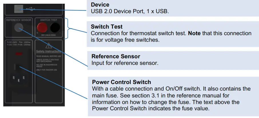
About the front panel:
- The on the front panel of the calibrator. must NEVER be connected to a voltage source.
- Thermostats connected to the switch test input must not be connected to any other voltage source during a test.
About the insertion tubes and insulation plug:
- Never leave hot insertion tubes which have been removed from the calibrator unsupervised — they may constitute a fire hazard or personal injeary.If you intend to store the calibrator in the optional aluminium carrying case after use. you must ensure that the instrument has cooled down to a temperature below 50°C/122°F before placing it in the carrying case.
- Never place a hot insertion tube in the optional carrying case.
- Use only insulation plugs supplied by AMETEK Denmark A/S.
- Never try to modify the insulation plugs to make them fit the sensor (CTC-1205 only)
About the fuses:
- The fuse box must not be removed from the power control switch until the mains cable has been disconnected.
- The two main fuses must have the specified current and voltage rating and be of the specified The use of makeshift fuses and the short-circuiting of fuse holders are prohibited and may cause a hazard.
![]() Caution – Hot surface
Caution – Hot surface
This symbol is visible on the grid plate ![]()
- Do not touch the grid plate, the well or the insertion tube when the calibrator is heating up — they may be very hot and cause bums.
- Do not touch the tip of the sensor when it is removed from the insertion tube/well — it may be very hot and cause
- Do not touch the handle of the calibrator during use — it may be very hot and cause bums.
- Over 50°C/122°F
If the calibrator has been heated up to temperatures above 50°C/122°F, you must wait until the instrument reaches a temperature below 50°C/122°F before you switch it off.
- Do not remove the insert from the calibrator before the insert has cooled down to less than 50°C/122°F.
![]() Caution — Cold surface
Caution — Cold surface
Below 0°C/32°F (applies only to the CTC-155 models)
- Do not touch the well or insertion tube when these are below 0°C/32°F – theymight create frostbite.
- If the calibrator has reached a temperature below 0°C/32°F, ice crystals may form on the insertion tube and the well. This, in turn, may cause the material surfaces to oxidize To prevent this from happening the insertion tube and the well must be dried. This is done by heating up the calibrator to 100°C/212°F until all water left has evaporated. Remove the insulation plug while heating up. It is very important that humidity in the well and insertion tube is removed to prevent corrosion and frost expansion damages.
![]() Caution… About the use:
Caution… About the use:
- Do not use the instrument if the fan is out of order.
- Before cleaning the calibrator, you must switch it off, allow it to cool down and remove all cables. About the well, insertion tube and grid plate:
- The well and the insertion tube must be clean and dry before use.
- Do not pour any form of liquids into the well. It might damage the well or cause a hazard.
- Scratches and other damage to the insertion tubes should be avoided by storing the insertion tubes carefully when not in use.
- The insertion tube must never be forced into the well. The well could be damaged as a result, and the insertion tube may get stuck.
- Before using new insertion tubes for the calibration. the insertion tubes must be heated up to maximum temperature 350°C (662°F) / 650°C (1202°F)! 660°C (1220°F)/ 1205°C (2201°F) for a period of minimum 30 minutes (CTC-350/652/660/1205 only).
- The insertion tube must always be removed from the calibrator after use. The humidity in the air may cause corrosion oxidation on the insertion tube inside the instrument. There is a risk that the insertion tube may get stuck if this is allowed to happen.
- If the calibrator is to be transported. the insertion tube must be removed from the well to avoid damage to the instrument. If the insertion tube is not removed from the CTC-1205 the ceramic well might crack.
![]() Note... The product liability only applies if the instrument is subject to a manufacturing defect. This liability becomes void if the user fails to follow the instructions set out in this manual or uses unauthorised spare parts.
Note... The product liability only applies if the instrument is subject to a manufacturing defect. This liability becomes void if the user fails to follow the instructions set out in this manual or uses unauthorised spare parts.
Setting up the calibrator
| ENVIRONMENTAL SPECIFICATIONS | |
| Ambient operating temperature range: | 0-50°C / 32-122°F |
| Storage temperature range: | -20-50ct / -4-122°F |
| Humidity range: | 5-90% RH. non-condensing |
| IP protection class: | IP10 |
| Altitude: | 0-2000 m / 0-3000 m (CTC-1205 only) |
| Electromagnetic Compatibility: | Tested for use in domestic establishment and in establishments directly connected to low voltage power supply network which supplies buildings used for domestic purposes as well as in an industrial electromagnetic environment as described in EN61326-1:2013. |
| POWER SUPPLY SPECIFICATIONS | |
| Line voltage/frequency: | 90-127VAC / 180-254VAC 47-63 Hz |
| IEC protection class: | Class I |
| Power consumption: | CTC-155 A/C: 140 VA max.CTC-350 NC: 1150 VA max.CTC-652 NC: 1150 VA max.CTC-660 NC: 1150 VA max.CTC-1205 NC: 650 VA max. |
The calibrator must not be used for any purposes other than those described in this manual, as it might cause a hazard.Before use Warning
- The calibrator has been designed for indoor use only and is not to be used in wet locations.
- The calibrator is not to be used in hazardous areas. where vapour or gas etc. may constitute a danger of explosion.
- The calibrator is not designed for operation in altitudes above 2000 meters (CTC-155/350/652/660)/ 3000 m (CTC-1205).
- The calibrator is a CLASS I product and must be connected to a mains outlet with a protective earth connection. Ensure the ground connection of the calibrator is properly connected to the protective earth before switching on the Always use a mains power cable with a mains plug that connects to the protective earth.
- To ensure the connection to protective earth any extension cord used must also have a protective earth.
- Only use a mains power cord with a current rating as specified by the calibrator.and which is approved for the voltage and plug configuration in your area.
- Always make sure to position the power cord and other connected cables in a secure way to prevent the risk of personnel
- To prevent the calibrator from tipping over and causing damage to equipment or systems, please avoid pulling the cables connected to the
- Before switching on the calibrator make sure that it is set to the voltage of the mains electricity
- Always position the calibrator to enable easy and quick disconnection of the power source (mains inlet socket).
- The on the front panel of the calibrator, must NEVER be connected to a voltage source.
- Thermostats connected to the switch test input must not be connected to any other voltage source during a test.
- Never use heat transfer fluids such as silicone, oil, paste. etc. in the dry-block These fluids may penetrate the calibrator and cause electrical hazard. damage or create poisonous fumes.
- The calibrator must be kept dear within an area of 20 cm on all sides and 1 metre above the calibrator due to fire
- After transport or storage in humid conditions or if the calibrator has not been heated up to minimum 100°C within the last 10 the instrument needs to be operated with a well temperature of at least 140°C for 2 hours before it can be assumed to meet all safety requirements of EN61010-1(CTC-350/6521660 only).
- Use only insulation plugs supplied by AMETEK Denmark A/S.
- Never try to modify the insulation plugs to make them fit the sensor (CTC-1205 only)
![]() Caution — Hot surface
Caution — Hot surface ![]()
This symbol is visible on the grid plate
- Do not touch the grid the well or the insertion tube as the calibrator is heating up — they may be very hot and cause bums.
- Do not touch the handle of the calibrator during use — it may be very hot and cause burns.
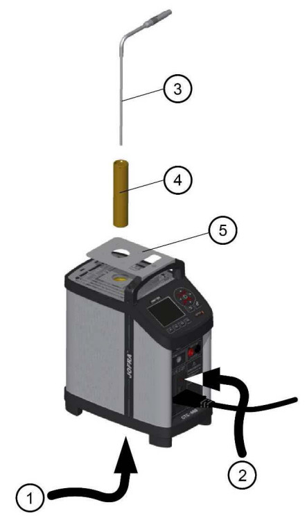
When setting up the calibrator, you must… (cf. figure next page):
- Place the calibrator on an even horizontal surface where you intend to use it and away from all draughts. The calibrator must be kept dear within an area of 20 an on all sides and 1 metre above the calibrator due to fire
 Caution…Do not use the instrument if the internal fan is out of order.
 - Ensure a free supply of air to the internal fan located at the bottom of the instrument (pos. 1). The area around the calibrator should be free of draught. dirt, flammable substances etc.
- Check that the fuse size corresponds to the applied voltage on (pos. 2). The fuse is contained in the power control switch (on/off switch (230V/115V)). Warning The two main fuses must have the specified current and voltage rating and be of the specified type. The use of makeshift fuses and the short-circuiting of fuse holders are prohibited and may cause a hazard.
- Check that the earth connection for the instrument is present and attach the cable.
- Place the sensor (pos. 3) in the insertion tube (pos. 4) as shown in the figure below. Caution… Before using new insertion tubes for the calibration in the CTC-350/6521660/1205 instruments the insertion tubes must be heated up to maximum temperature 350°C(662°F) / 650°C (1202°F)! 660°C (1220°F)/ 1205°C (2201 °F) for a period of minimum 30 minutes.
- In order to protect the sensor and its connections use the thermal protection shield (129264 — pos. 5) at high temperatures (CTC-6521660 only).
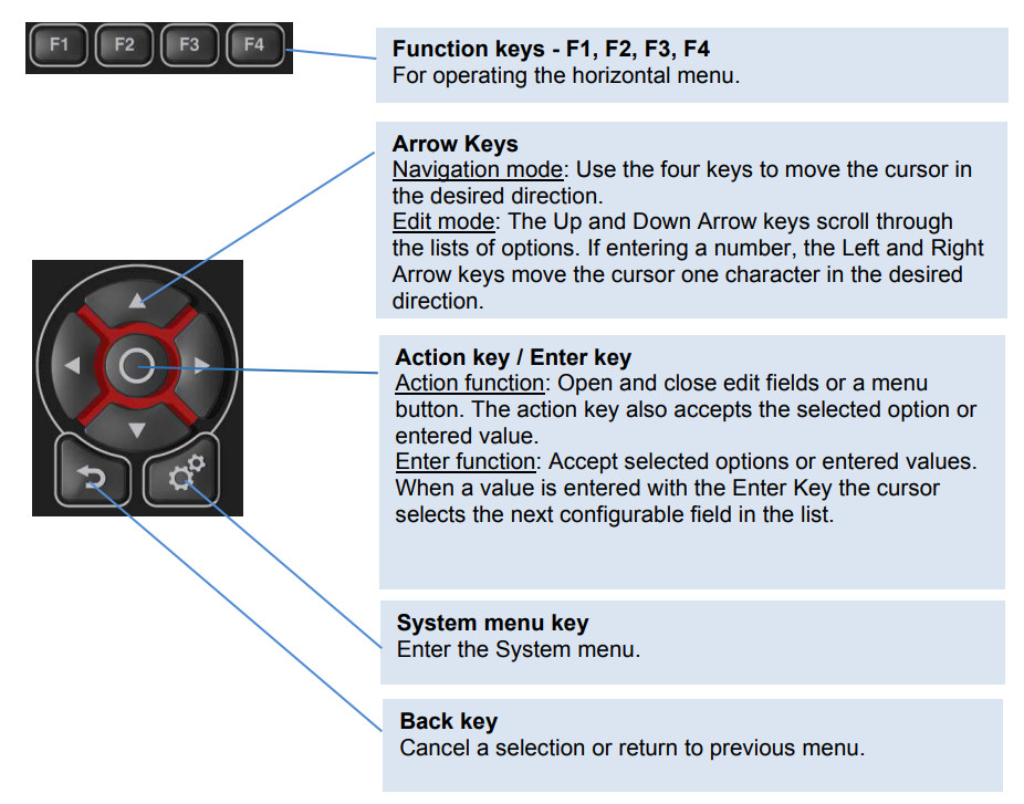
Keypad- Functions
Display

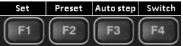
- Horizontal menu barProvides you with the relevant menu options that can be selected at the present point. Each option can be selected and activated by pressing the function keys (Fl. F2. F3 and F4).
- Process IndicatorIndicates the status of the current process.
- “Time to stable” SelectionShows the selected specified stability criteria and states a time when the stable situation can be achieved.
- Reference sensor infoShows the reference sensor selected. The serial number of the external reference sensor is read from the intelligent reference sensor and displayed in this field.
- Memory readingShows the current memory selected from the System menu.
- Warning/Error symbols.If a warning or an error symboloccurs during operation, action needs to be taken.
- Real TimeClock and date display.
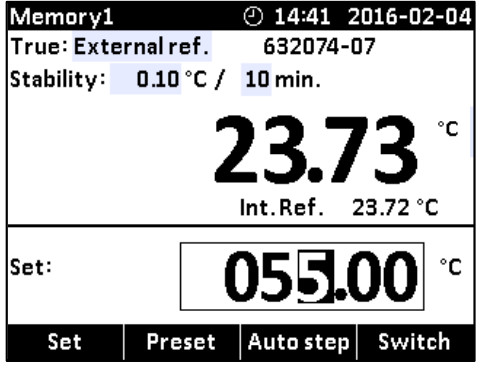
- True temperature readingShows the numeric value of the temperature being measured. Can be either the internal reference sensor or an external reference sensor.
- UnitsShows the unit of the current measurement.
- Internal Reference temperature readingShows the temperature of the well.
- Set temperature readingShows the numeric value of the current set temperature selected.
Connections
Stability of temperature values
The stability of the TRUE temperature is indicated by the following messages:
- “Not stable”: Indicates that the measured temperature is not yet within the specified stability criteria.
- 4:29 Indicates “Time to stable”: The temperature changes are within the specified stability criteria and states a time (in minutes and seconds) when the stable situation can be achieved.
- Indicates that the “stable” situation is achieved and for how long the calibrator has been stable. When the calibrator has been stable for more than 99 minutes, only the stable sign is displayed (time is no longer displayed).
- If External reference is selected as TRUE, the stability criteria will refer to this. The criteria can be changed, however, if the temperature stability criteria is set wider or the stability time is set shorter, the calibrator may not reach the SET temperature.
When the instrument is heating up and cooling down indication of this will be shown as following symbols:
- The instrument is heating up.
- The instrument is cooling down (CTC-155 only).
- The instrument is cooling down (CTC-350/652/660/1205 only).
 The instrument is heating up.
 The instrument is cooling down (CTC-350/652/660/1205 only).
Hot and cold symbols will be displayed in the upper black info bar when:
- the well temperature is below 5°C.
- the well temperature is above 45°C.
Operating the calibrator
Operating principle
The calibrator is operated using the Functions keys, the Arrow keys and the Action/Enter key.
- Press the Functions keys to operate the horizontal menu bar.
- Press any of the (Arrow) keys to enter Navigation Mode. Editable fields will be highlighted in blue.
- Use the Arrow) keys to move between the configurable fields within the display. Selected fields will be highlighted in dark blue.
- Press the (Enter) key to access the selected field for editing.
- Use the (Up) and (Down) Arrow keys to select a new value.
- Press the (Enter) key to accept the new value
- To exit the Navigation Mode press the (Back) key. The (Back) key is also used to cancel a selection or to return to a previous menu.
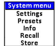
The System menu can be accessed at any stage of operation:
- Press the (System) key to display the System menu.
- Use the (Up) anc (Down) Arrow keys to scroll in the list.
• System Settings menu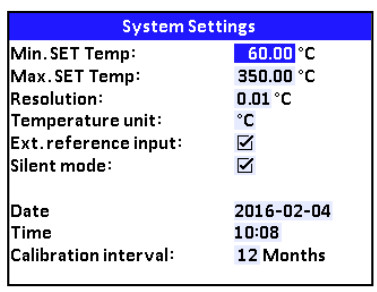 1. Use the e (Enter) key and the A (Up) and V(Down) Arrow keys to access editable fields, select new values and accept new values.
![]() Note…
Note…
- If the current set-temperature is higher than the new max-temperature, you will need to adjust the set-temperature. The instrument will immediately begin to cool (if required) as soon as the new max-temperature is accepted.
- The calibration interval can be set between 1 and 99 months. When the calibration interval is exceeded, a yellow warning symbol will appear in the upper part of the display. The recalibration interval is not used for the external reference sensor. The interval for this sensor is stored in the intelligent sensor.
- If the Ext. reference input setting is disabled, it will not be possible to select the external reference or SET follows true from the Mode menu. Only the internal reference can be selected and displayed in the main display (C-models only).
- If Silent mode is selected, the cooling speed will be reduced.

Presets menu

- I he preset temperatures can be changed manually using the (Arrows) keys.
![]() Note...Temperature range is limited by Min. SET Temp. and Max. SET Temp. settings editable in the System Settings menu and by the temperature range of the external reference sensor, if connected.
Note...Temperature range is limited by Min. SET Temp. and Max. SET Temp. settings editable in the System Settings menu and by the temperature range of the external reference sensor, if connected.
• System Info menu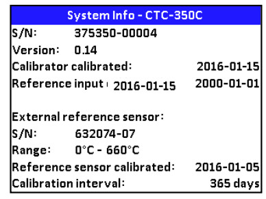
- In the System Info menu important information such as serial numbers and calibration dates of both the instrument and the external reference sensor are given. It is not possible to edit any fields in this menu.
• Store menu (Save Settings)
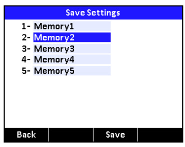 After you have configured the instrument, you can save the setup for future use using the Store function.
- Use the (Up) and (Down) Arrow keys to select the Memory-setup you want to modify, and press F3(Save). The new configuration is now saved.
- You can change the name of the highlighted saved setup by pressing (Enter), and then using the (Up) and (Down) Arrow keys to change the characters. The name is limited to seven (7) characters.
- Press F3 to save the new name.
• Recall menu
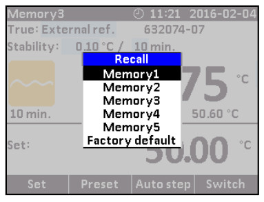 To recall your memory setups select the Recall function.
- Use the(Up) and (Down) Arrow keys to to scroll in the setup-list.
- Select the requested setup, and press (Enter). The name of the setup will appear in the upper-left corner of the display. If selecting the Factory default function the active setup will be reset and change to the initial setting.
Starting the calibrator
Switch on the calibrator using the power control switch.A start up screen is displayed and then replaced with the main menu screen:
 The functions in the horizontal menu bar are available using the Functions soft keys Fl— F4. For Operating principle — See section 4.1.
Selecting a TRUE — reference sensor (C-models only)
1. Press one of the ![]() (Arrow) keys and
(Arrow) keys and ![]() (Enter) key to access the Mode menu.
(Enter) key to access the Mode menu.
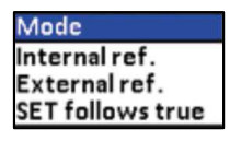 You can choose between one of the following sensor constellations:
- Internal reference source (A and C models)
- External reference source (C models only)
- SET follows TRUE (C-models only)
Internal reference source
The internal reference sensor will be displayed as the TRUE value on the main screen.
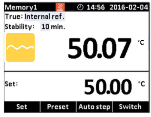
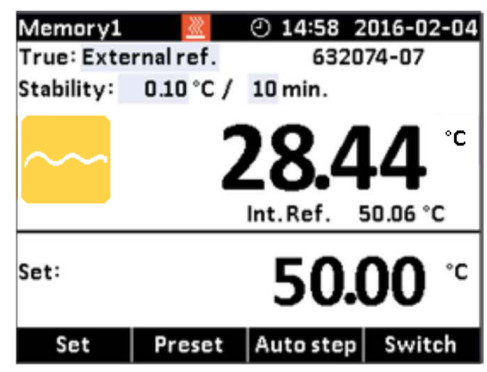
The calibrator has a set of internal stability criteria it shall meet before stability is indicated. The stability time may be set beyond the internal stability criteria. The stability time can be set (in minutes) using integers from 5 — 99External reference source (C-models only)The TRUE value on the main screen will be read from the Intelligent Reference Sensor connected to the REF. INPUT on the front panel (see section 3.4). The calibrator automatically reads the calibration data and serial number of the Sensor.
 SET follows TRUE (C-models only)This function enables you to reach the TRUE temperature measured by the External reference sensor. The TRUE value on the main screen will be read from the Intelligent Reference Sensor connected to the REF. INPUT on the front panel (see section 3.4). The calibrator automatically reads the calibration data and serial number of the Sensor.
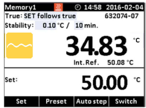
![]() Note... that when “SET follow true” is selected, the calibrator will control the temperature to the TRUE temperature. This means that it could take longer time before the calibrator indicates stability.
Note... that when “SET follow true” is selected, the calibrator will control the temperature to the TRUE temperature. This means that it could take longer time before the calibrator indicates stability.
Stability setting
True: Internal referenceWhen internal reference is selected the calibrator uses a set of minimum intemal stability criteria that shall be met before stability is indicated.The stability time can be adjusted from the minimum internal stability time (typical 5 min) up to 99 min.True: External referenceWhen internal reference is selected the user can adjust both stability tolerance and stability time. The Stability tolerance can be set between 0.01°C to 1.00°C. The tolerance should be set low enough to utilize the good temperature stability of the calibrator —however a low value also gives a longer time to be stable.The stability time can be set from 1 — 99 minutes. When the TRUE temperature has reached the specified Stability tolerance during the specified Stability time, then the stability indicator in the main screen will turn green.
Selecting the set-temperature
![]() Note… Temperature range is limited by Min. SET Temp. and Max. SET Temp. settings editable in the System Settings menu and by the temperature range of the external reference sensor, if connected.The set-temperature can be entered both manually and by selecting a preset temperature.
Note… Temperature range is limited by Min. SET Temp. and Max. SET Temp. settings editable in the System Settings menu and by the temperature range of the external reference sensor, if connected.The set-temperature can be entered both manually and by selecting a preset temperature.
- For manually use press in F1(Set)
- Use the (Arrow) keys to enter the temperature requested.
- Press (Enter) to accept the entered temperature.
- For selecting the preset temperature press F2(Preset).
- Select one of the 4 temperature options available from the menu bar by pressing the correspondent Function key (F1 — F4).
- The set-temperature is selected, once the Function key has been pressed.
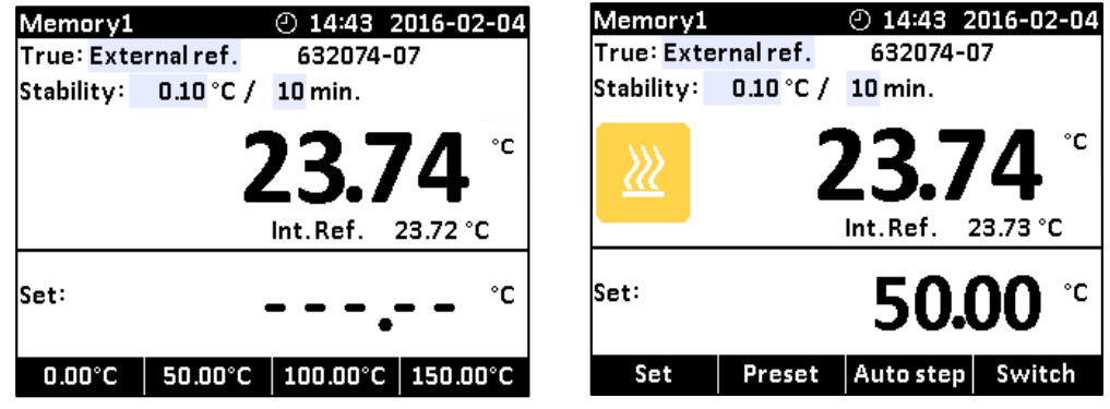
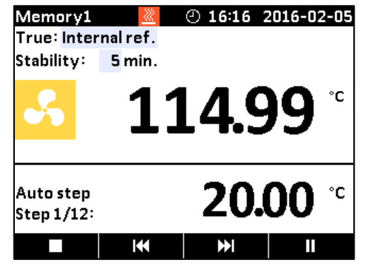
The calibrator will now heat up / cool down.The starting point is the last chosen set-temperature (even if the instrument has been switched off).The top display continuously shows the read-temperature and the lower display shows the set-temperature. In the top display the calibrator will indicate the estimated time in whole minutes until the calibrator will be stable.
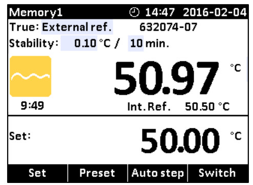
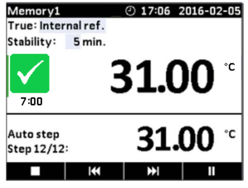
When the calibrator is stable the display will show a green ![]() checkmark symbol and the instrument will emit an audible alarm. The instrument will indicate in minutes and seconds for how long the instrument has been stable.4.6.1 Editing the preset set-temperature
checkmark symbol and the instrument will emit an audible alarm. The instrument will indicate in minutes and seconds for how long the instrument has been stable.4.6.1 Editing the preset set-temperature
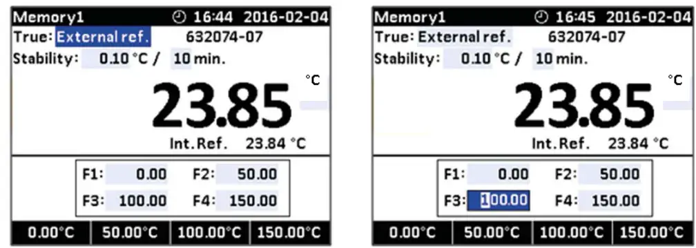
It is possible to change the preset set temperature to whatever value desired.
- Press F2 (Preset)
- Press one of the (Arrow) keys and an editable field displaying the preset set temperatures appears.
- Navigate to the set temperature field using the arrows.
- Press (Enter) to access the editable field and use the arrows (Up) and (Down) to select a new set value.
- Press (Enter) to accept the new set value.
- Press (Back) to return to the previous menu.
Auto Step function
Auto Step is used to step automatically between a range of different calibration temperatures. This is useful when calibrating sensors in places which are hard to reach, and when calibrating sensors for which the output is displayed in a different location.![]() Note…Temperature range is limited by Min. SET Temp. and Max. SET Temp. settings editable in the System Settings menu and by the temperature range of the external reference sensor, if connected.4.7.1 Running an Auto Step test
Note…Temperature range is limited by Min. SET Temp. and Max. SET Temp. settings editable in the System Settings menu and by the temperature range of the external reference sensor, if connected.4.7.1 Running an Auto Step test
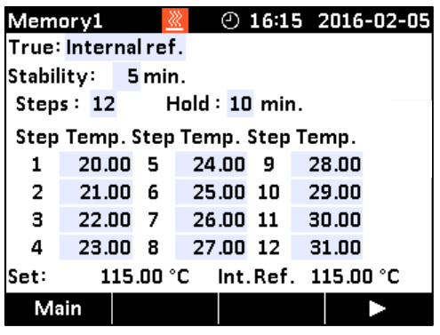
- Press F3(Auto Step) to access the Auto Step setup. If you wish to return to the Main screen press F1 (Main).
- Press one of the (Arrow) keys to access the editable fields for new values:• No of steps: the number of temperature steps per direction (TI→Tx) can be set using integers from 2 to 12.You must select minimum 2 steps, maximum 12 steps.• Hold time: defines the time (in minutes) the temperature is maintained (after it is stable) for each step.• Step values: must be set within the sensors permitted range.
- Press (F4) to start the Auto Step test.The Auto Step test is now in progress. While the Auto Step test is in progress, 4 options are available:• Stop : Press ■ (F1) to stop the Auto Step test. The process will end.Pressing the (F4) key the process will start again running step 1.• Previous : Press (F2) to force the test to jump a step backwards to the previous running step regardless of the step’s stability.• Next : Press (F3) to force the test to jump a step forwards to the next running step regardless of the step’s stability.• Pause : Press II (F4) to pause the test. Pressing start (F4) again, the process will continue running from the current step.
 The Auto Step test is now in progress. While the Auto Step test is in progress, 4 options are available:• Stop : Press ■ (F1) to stop the Auto Step test. The process will end.Pressing the
 4.7.2 The calibrator’s Auto Step procedure
- Once the Auto Step test is started, the calibrator starts working towards the given set temperature. An audible alarm will be emitted once the calibrator is stable.
- The calibrator will wait the specified amount of hold time. The instrument indicates this by counting down the amount of time remaining.
- The calibrator will then go to the next step. The procedure is the same as for the first step. This process will be repeated until the last step has been executed and the function has been completed.
- The -cured TRUE temper.’ -es for each step are displayed during operation.
Switch Test function
Switch Test automatically locates the switch temperature of a thermostat.Three parameters are required:
- Start temperature (Ti)
- End temperature (T2)
- Rate of change in temperature pr. minute (Rate).
Dead band of a thermostat can also be determined here. Where the dead band determines the tolerance between the upper switch temperature and the lower switch temperature of the thermostat.
4.8.1 Running a Switch Test
WarningThermostats connected to the switch test input must not be connected to any other source during test.![]() Note…Before running the Switch Test, make sure that the switch is connected to the Switch Test input.
Note…Before running the Switch Test, make sure that the switch is connected to the Switch Test input.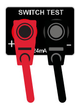
![]() Note…Temperature range is limited by Min. SET Temp. and Max. SET Temp. settings editable in the System Settings menu and by the temperature range of the external reference sensor, if connected.
Note…Temperature range is limited by Min. SET Temp. and Max. SET Temp. settings editable in the System Settings menu and by the temperature range of the external reference sensor, if connected.
- Press F4 (Switch) to access the Switch Test setup. If you wish to return to the Main screen press CO F1(Main).The small graph illustrates the current Ti, T2 and dead band selections Note that Ti can be greater than T2.
- Press one of the ( Arrow-) keys to access the editable fields for new values:• Ti : First set temperature• T2 Second set temperature• Dead band : To determine dead band, toggle between “Yes” (a two-way-temperature measurement) and No (a one-way-temperature measurement). A dead band result is only measured when dead band is set to ‘Yes”.• Rate : The permitted range is 0.01 – 10.0°C/min. /0.02 – 18.0°F/min.• Test runs: Can be set from 1 to 3 making it possible to run the test more than once. Note… the Rate should be set so that the thermostat sensor can follow the temperature in the calibrator’s well.
- Press (F4) to start the Switch Test.The Switch test is now in progress.While the Switch Test is in progress 2 options are available:• Stop : Press ■ (F1) to stop the Switch Test. The process will end and the results will be deleted from the results list. Pressing the (F4) key the process will start from the beginning heating towards T1.• Results : Press (F3) to display the current Switch Test result. The results change as the test progresses. The results list is also accessible from the Switch Test menu screen.
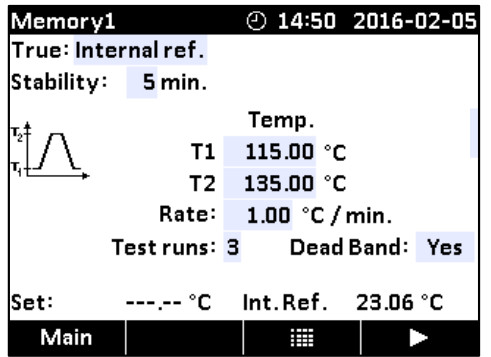 The small graph illustrates the current Ti, T2 and dead band selections Note that Ti can be greater than T2.
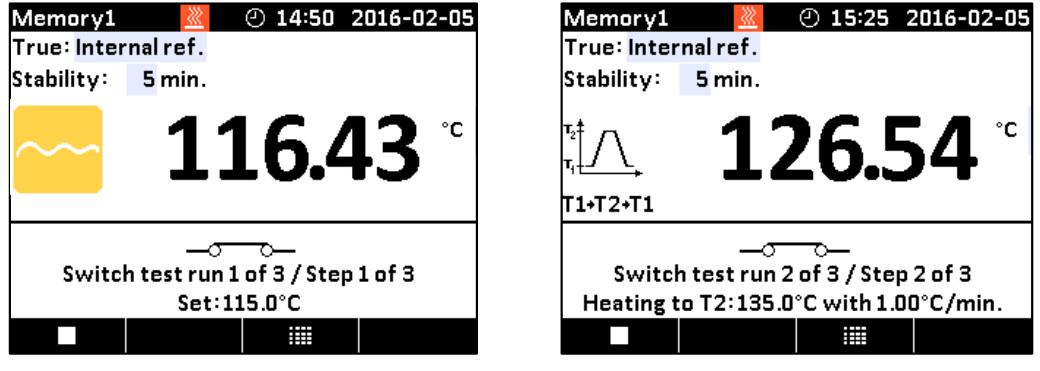 The Switch test is now in progress.While the Switch Test is in progress 2 options are available:• Stop : Press ■ (F1) to stop the Switch Test. The process will end and the results will be deleted from the results list. Pressing the
 4.8.2 The calibrator’s Switch Test procedure
- Once the Switch Test is started, the calibrator starts working towards T, as quickly as possible. The calibrators temperature changes (heating or cooling) and switch status are shown in the display.
- When T, is achieved and the temperature is stable, the text and the graphic in the bottom of the screen will change accordingly.
- The calibrator now starts working towards T2 at the specified Rate.
- In a normal situation, the thermostat changes state before T2 is achieved. If T2 is achieved and the temperature is stable, no results will be displayed.
- When dead band is not selected (single temperature change) (the graphic indicates the choice), the finished switch test result is displayed.When dead band is selected (two switch changes), the calibrator starts working towards Ti at the specified Rate.
- Normally, the thermostat changes state before T, is achieved. If Ti is reached and the temperature is stable, no results will be displayed.
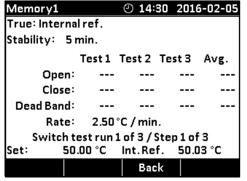
The finished switch test results are displayed in the results list by pressing ![]() (F3). The results show the temperature when the thermostat has closed and the temperature when it has opened — whichever comes first. The difference between these 2 temperatures is calculated as the dead band.
(F3). The results show the temperature when the thermostat has closed and the temperature when it has opened — whichever comes first. The difference between these 2 temperatures is calculated as the dead band.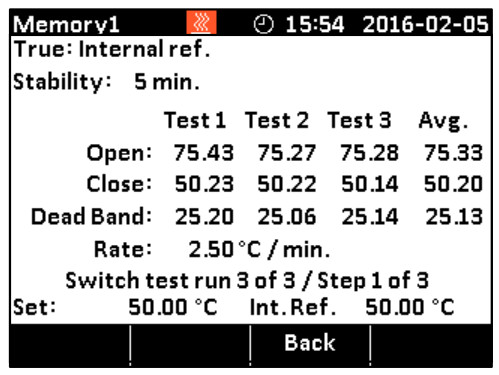
Setting the mains voltage and replacing the main fuses
Replacing the main fuses
Warning
- The calibrator must be switched off before any attempt to service the instrument is made. There are no user-serviceable parts inside the calibrator.
- The fuse box must not be removed from the power control switch until the mains cable has been disconnected.
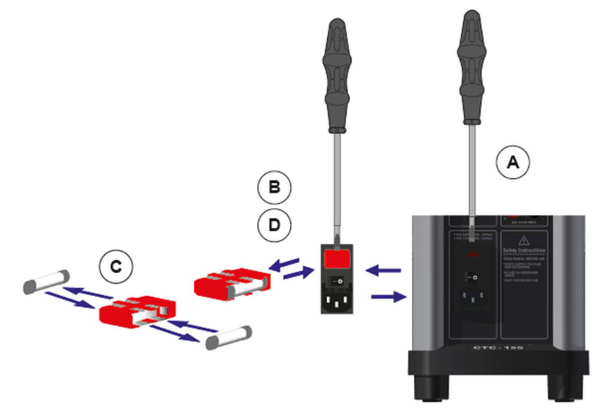
- The two main fuses must have the specified current and voltage rating and be of the specified type. The use of makeshift fuses and the short-circuiting of fuse holders are prohibited and may cause a hazard.A. Locate the main fuses in the fuse box in the power control switch and check the voltage of the power control switch (on/off switch (230V/115V)). If the voltage of the power control switch differs from the line voltage, you must adjust the voltage of the power control switch.B. Open the lid of the fuse box using a screwdriver and remove the fuse box.C. Replace the fuses. The fuses must be identical and should correspond to the line voltage.
- CTC-155/350/652/660: 115V: 10AF/250V = 60B302. 230V: 5AF/250V =127573
- CTC-1205: 115V: 8AT/250V = 127211. 230V: 4AT/250V = 127210If the fuses blow immediately after you have replaced them. the calibrator should be returned to the manufacturer for service.D. Slide the fuse box into place with the correct voltage turning upwards.
 A. Locate the main fuses in the fuse box in the power control switch and check the voltage of the power control switch (on/off switch (230V/115V)). If the voltage of the power control switch differs from the line voltage, you must adjust the voltage of the power control switch.B. Open the lid of the fuse box using a screwdriver and remove the fuse box.C. Replace the fuses. The fuses must be identical and should correspond to the line voltage.
After use
Storing and transporting the calibrator
![]() Caution…
Caution…
The following guidelines should always be observed when storing and transporting the calibrator. This will ensure that the instrument and the sensor remain in good working order. Warning
- The calibrator must be switched off before any attempt to service the instrument is made. There are no user serviceable parts inside the calibrator.
- Remember to use appropriate protective equipment or get help when carrying the calibrator (for a longer distance) in order to prevent injuries from dropping the calibrator.
The following routine must be observed before the insertion tube is removed and the instrument switched off.
![]() Over 50°C/122°FIf the calibrator has been heated up to temperatures above 50°C/122°F, you must wait until the instrument reaches a temperature below 50°C/122°F before you switch it off.
Over 50°C/122°FIf the calibrator has been heated up to temperatures above 50°C/122°F, you must wait until the instrument reaches a temperature below 50°C/122°F before you switch it off.![]() Below 0°C/32°F(applies only to the CTC-155 models)
Below 0°C/32°F(applies only to the CTC-155 models)
- Do not touch the well or insertion tube when these are below 0°C/32°F – they might create frostbite.
- If the calibrator has reached a temperature below 0°C/32°F, ice crystals may form on the insertion tube and on the well. This, in turn, may cause the material surfaces to oxidize. To prevent this from happening, the insertion tube and the well must be dried. This is done by heating up the calibrator to min. 100°C/212°F until all water left has evaporated.
Remove the insulation plug while heating up.It is very important that humidity in the well and insertion tube is removed to prevent corrosion and frost expansion damages.
Switching off the calibrator
- Switch off the calibrator using the power control switch. Note that the calibration procedure may be interrupted at any time using the power control switch. Switching off the calibrator during the calibration process will not damage either the instrument or the sensor.
- Remove the insertion tube from the calibrator using the tool for insertion tube supplied with the instrument as shown in the figure.

![]() Caution — Hot surfaceDo not remove the insert from the calibrator before the insert has cooled down to less than 50°C/122°F
Caution — Hot surfaceDo not remove the insert from the calibrator before the insert has cooled down to less than 50°C/122°F![]() Caution…
Caution…
- The insertion tube must always be removed from the calibrator after use. The humidity in the air may cause corrosion oxidation on the insertion tube inside the instrument. There is a risk that the insertion tube may get stuck if this is allowed to happen.
- If the calibrator is to be transported long distances, the insertion tube must be removed from the well to avoid damage to the instrument. If the insertion tube is not removed from the CTC-1205 the ceramic well might crack.
Warning
- Never leave hot insertion tubes which have been removed from the calibrator unsupervised — they may constitute a fire hazard or personal injury. If you intend to store the calibrator in the optional aluminium carrying case after use, you must ensure that the instrument has cooled to a temperature below 50°C1122°F before placing it in the carrying case.
- Never place a hot insertion tube in the optional carrying case.
- Do not touch the well or insertion tube when these are deep frozen — they might create frostbite.
 report this ad
![]()
References
[xyz-ips snippet=”download-snippet”]