![]() SVT-3PRO, SVT-4PROQuick Start Guide
SVT-3PRO, SVT-4PROQuick Start Guide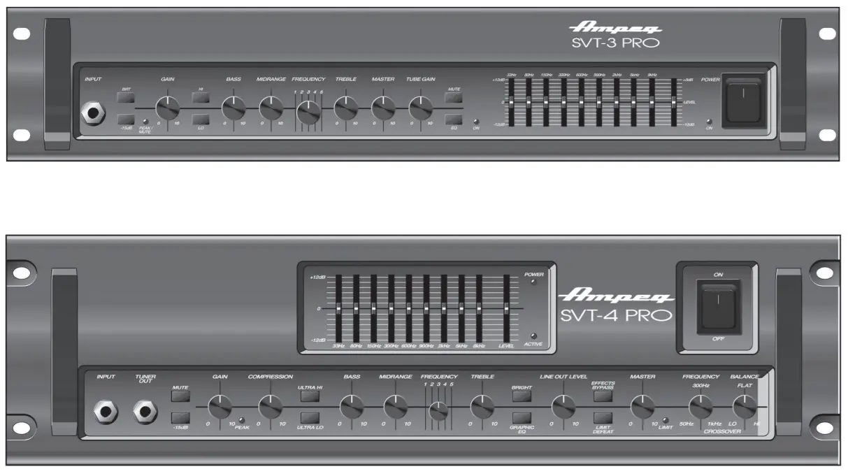
What’s in the Box
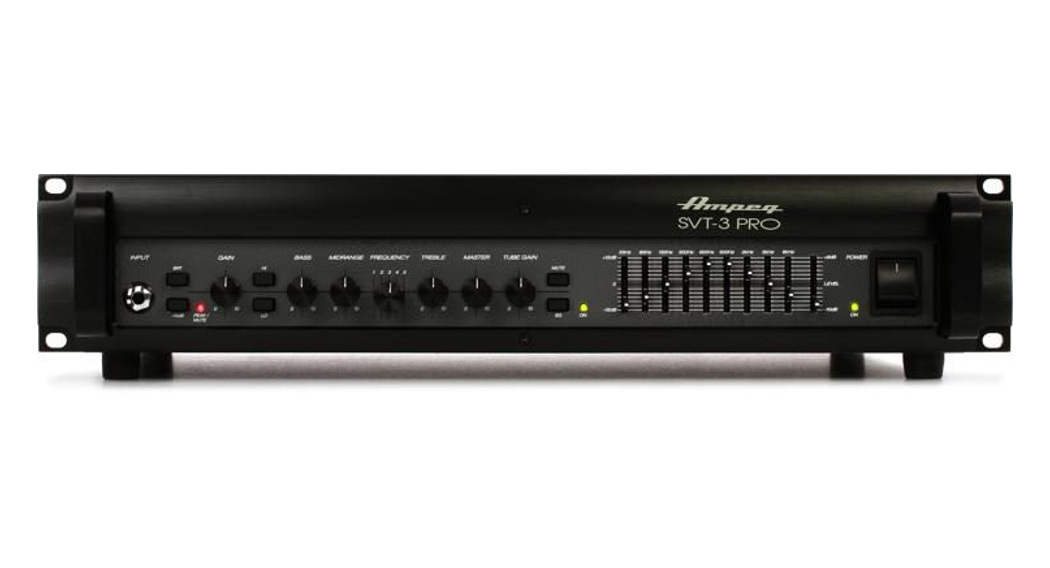
- SVT®-3PRO or SVT-4PRO Amplifier,
- Power Cable,
- and Quick Start Guide.
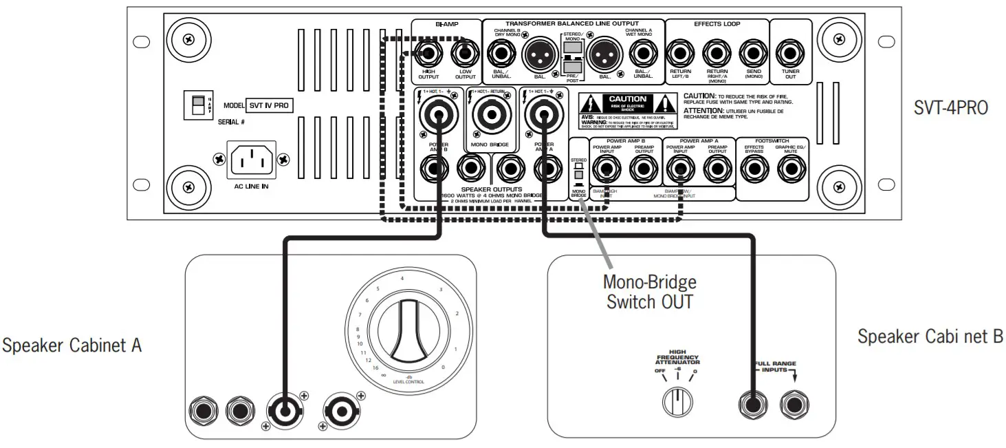
Hookup Diagrams
Standard Setup

Parallel Setup
Daisy Chaining
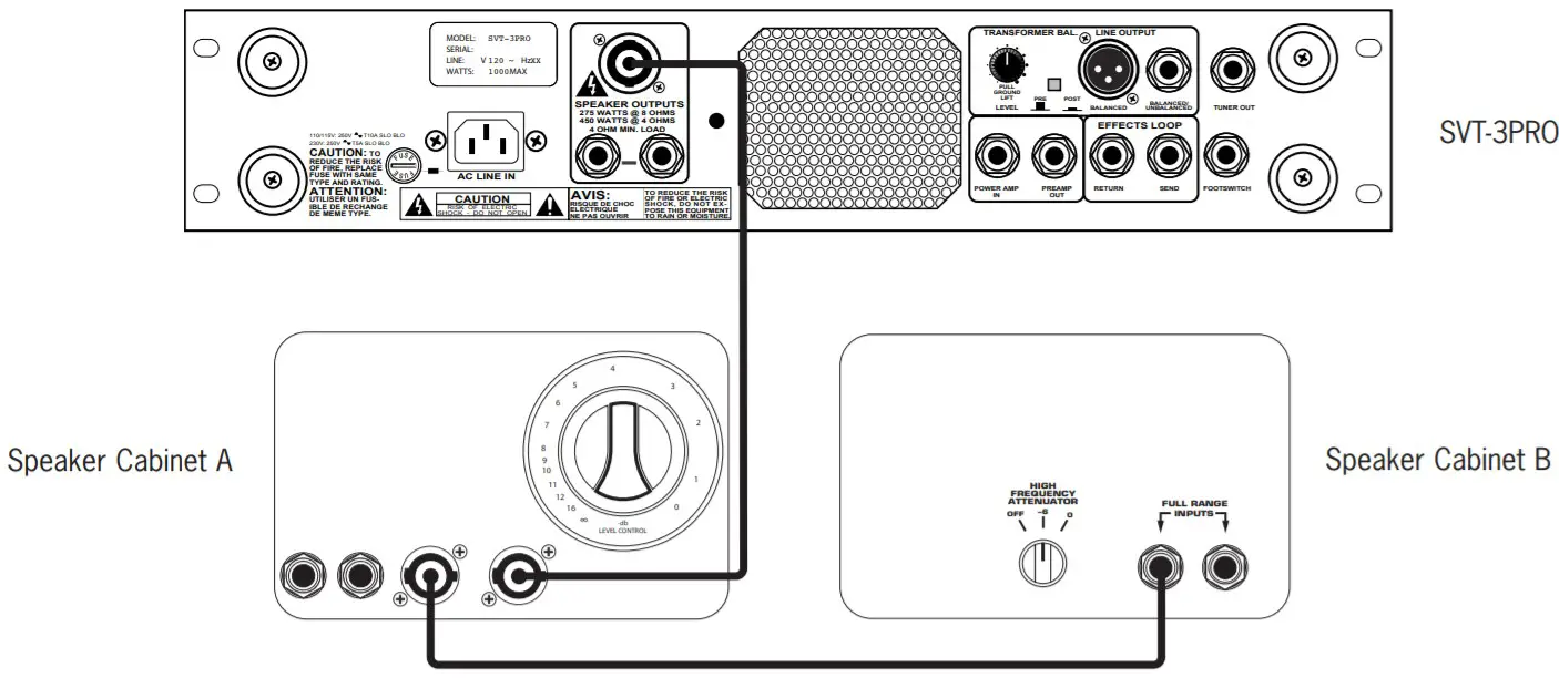 Note: Use same impedance cabinets in parallel setups and when daisy-chaining
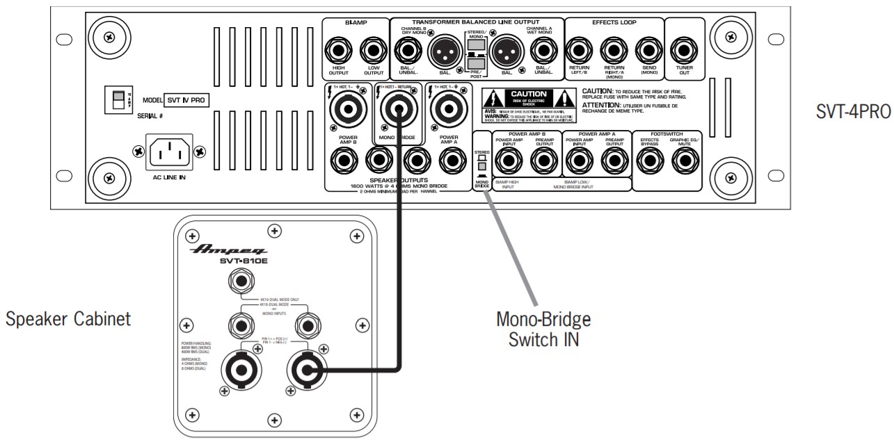
Mono-Bridged Setup
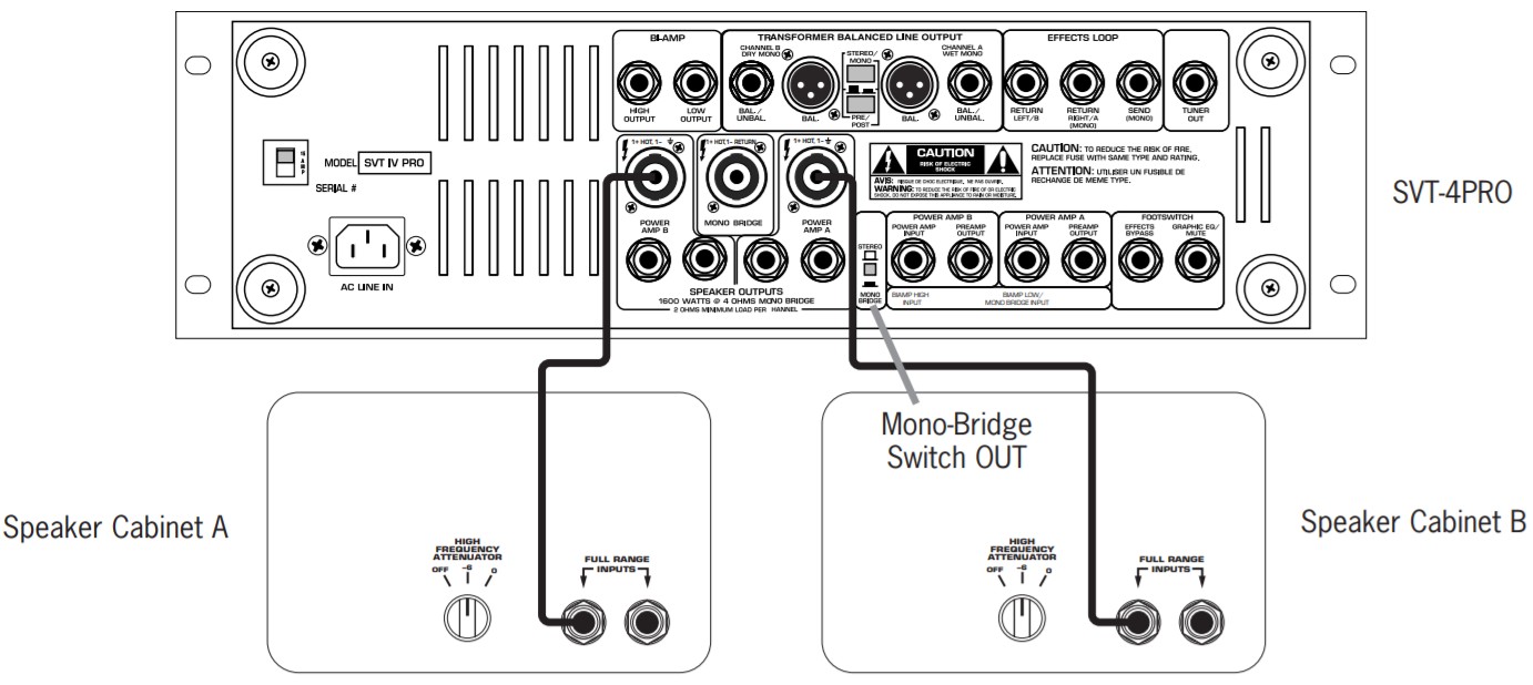
Dual Mono Setup
Bi-Amp Setup
Front & Rear Panels
 |
 |
 |
 |
Front & Rear Panel Descriptions
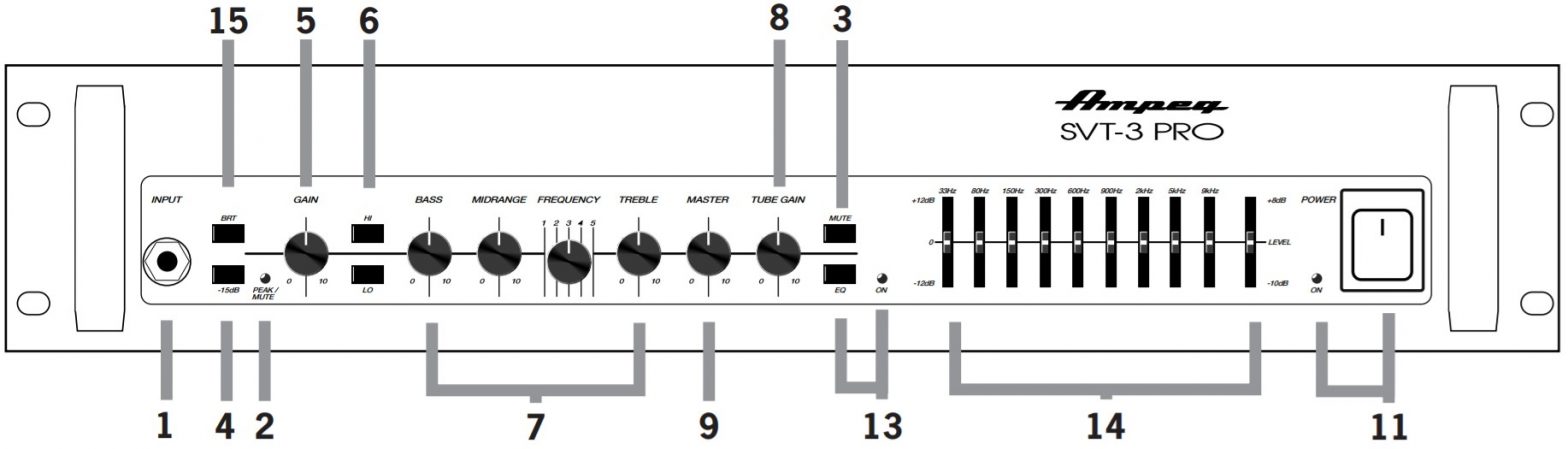
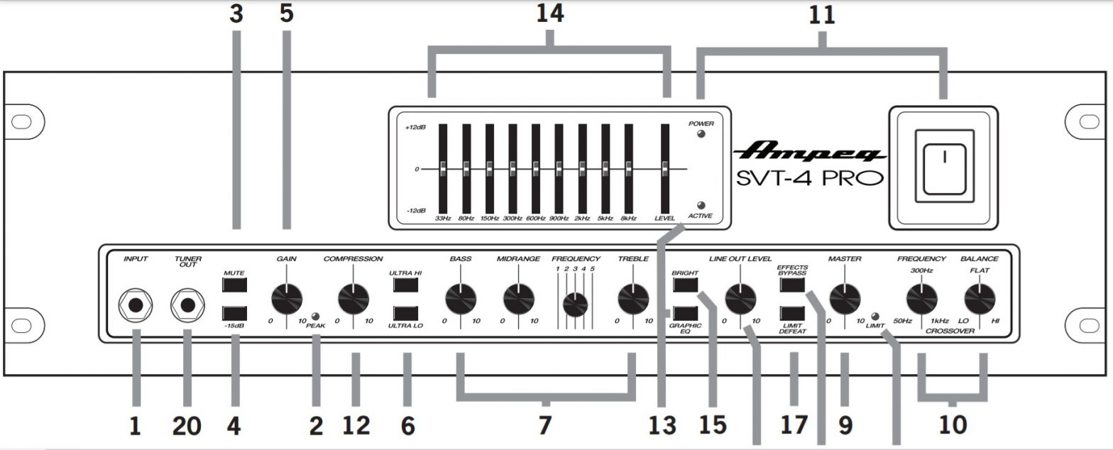
- 1/4″ Inputs: Connect a passive or active instrument to the Input jack.
- Peak/Mute LED: Indicates when the input signal is clipping or when the Mute is engaged.
- Mute Switch: Mutes all outputs except for the Tuner Out.
- Pad: Reduces input level by 15 dB.
- Gain Knob: Varies the intensity of the signal sent to the preamplifier.
- Ultra Hi/Ultra Lo Switches: Boosts high or low frequencies.
- EQ Knobs: Boost or cut the levels at certain frequencies to enhance the sound.
- Tube Gain: Varies the intensity of the signal sent to the preamp tubes.
- Master Knob: Controls the overall speaker output and headphone levels.
- Crossover Adjustment Knobs: Controls the frequency and balance when in Bi-Amp mode.
- Power Switch/Power LED: Turns the power on or off. LED indicates power on or off.
- Compression: Controls the amount of compression applied to the input signal.
- EQ Switch/LED: When engaged, the 9-Band Equalizer is active.
- 9-Band Graphic EQ: Boost or cut the levels at set frequencies to enhance the sound.
- Bright Switch: Boosts high frequencies.
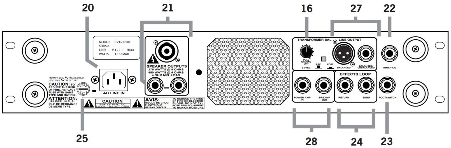
- Line Out Level: Varies the level of the signal sent to the Transformer Balanced Line Outputs.
- Limit Defeat: This allows the internal Limiter to be turned off.
- Effects Bypass: Bypasses the Effects Loop.
- Limit LED: Illuminates when the signal triggers the internal Limiter.
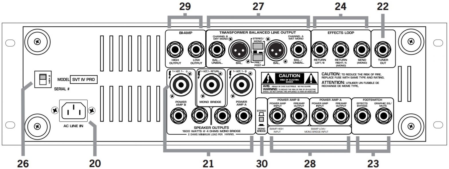
- Input Power Connector: Input socket for power cable connection.
- Speaker Outputs: Speakon® / 1/4″ TS outputs for connecting speaker cabinets.
- Tuner Output: Feeds an external tuner.
- Footswitch Input: Control the Mute and FX functions using a footswitch.
- Effects Loop Send/Return: Connect the input and output of an external FX processor.
- Fuse: Overload and AC line surge protection.
- Circuit Breaker: Overload and AC line surge protection.
- Transformer Balanced Line Out: Line level output. Switches to optimize output to a mixer or recorder.
- Patch Input/Output: Power Amp In bypasses the internal preamp. Pre Amp Out feeds an external amplifieror powered speaker.
- Bi-Amp High/Low Outputs: High and Low-Frequency Outputs for Bi-Amp mode.
- Mono Bridge Switch: Turns the Bi-Amp function on/off.
Getting Started
- Read and understand the included “Important Safety Instructions.”
- Make sure the power switch is off before making any connections.
- Push the line cord securely into the amplifier’s IEC connector and plug the other end into a grounded ACoutlet. The amplifier may accept the appropriate voltage as indicated near the IEC connector.
- Connect an instrument to the SVT-3PRO/SVT-4PRO Input jack with a 1/4″ (shielded) instrument cable.Connect (non-shielded) speaker cables to speaker cabinets with 1/4″ TS or Speakon ends depending on the model.
- With all volume controls fully off, turn the amplifier on by pressing the Power Switch to the on position.
- While playing the instrument, adjust the Gain and Master controls to the preferred level.
- Adjust the EQ knobs to taste.
Technical Specifications
| SVT-3PRO | SVT-4PRO | |
| Output Power Rating | 275W RMS @ 8 5% THD450W RMS @ 4 5% THD | Mono-Bridged:900W RMS @ 8 (3% THD)Mono-Bridged 1200W RMS @ 4 (3% THD)2x600W RMS @ 2 (3% THD)2x490W RMS @ 4 (3% THD)2x300W RMS @ 8 (3% THD) |
| Maximum Gain | 63dB | 68dB Bridged Output |
| Tube Complement | 12AX7 (4)12AU7 (1) | 12AX7 (3) |
| Power Requirements | ~100-120 VAC, 50-60 Hz, 390W~200-240 VAC, 50-60 Hz, 390W | ~100-120 VAC, 50-60 Hz, 1.4 kVA, 1.4 kW~200-240 VAC, 50-60 Hz, 1.4 kVA, 1.4 kW |
| Size (H x W x D) | 4.0 x 19.0 x 17.4 in102 x 442 x 394 mm | 5.6 x 19.0 x 17.4 in142 x 483 x 394 mm |
| Weight | 26.0 lb/11.8 kg | 39.5 lb/17.9 kg |
All specifications subject to change
![]()
WARRANTY AND SUPPORT
Visit WWW.AMPEG.COM to…
- identify WARRANTY coverage provided in your local market. Please keep your sales receipt in a safe place.
- retrieve a full-version, printable OWNER’S MANUAL (English only) for your product.
- REGISTER your product.
- CONTACT Technical Support, or call 818-575-3600.
www.ampeg.comYamaha Guitar Group, Inc.26580 Agoura Road, Calabasas, CA 91302-1921 USAPart No. 40-00-0530 Rev. B Supplier’s Declaration of Conformity47 CFR § 2.1077 Compliance Information
Unique Identifier: Ampeg SVT-3PRO, SVT4-PROResponsible Party – U.S. Contact Information:Yamaha Guitar Group, Inc.26580 Agoura RoadCalabasas, CA 91302-1921(818) 575-3600https://ampeg.com/
FCC Compliance Statement:
This device complies with Part 15 of the FCC Rules. Operation is subject to the following two conditions: (1) This device may not cause harmful interference, and (2) this device must accept any interference received, including interference that may cause undesired operation.There are various types of fuses, and replacing them with different types may cause malfunction, electric shock, or fire. Be sure to confirm you are replacing the correct fuse with electrical rating and specifications.Each number and symbol represent the following:Example: T3AL250V(1) T, (2)![]() (3) L, and(4)■V are shown below.
(3) L, and(4)■V are shown below.
- A symbol indicating relative fusing time / current characteristics T: Time lag type, F: Fast-acting type.
 A: Rated current
- A symbol indicating the blocking capacity L: Low cutoff capacity, E: Medium cutoff capacity, H: High cutoff capacity.
- ■V: Rated voltage
© 2021 Yamaha Guitar Group, Inc. All rights reserved.Ampeg and SVT are trademarks or registered trademarks of Yamaha Guitar Group, Inc. in the U.S.and/or other jurisdictions. Speakon is a registered trademark of Neutrik AG Corporation.Serial No.: ______
References
[xyz-ips snippet=”download-snippet”]