![]()
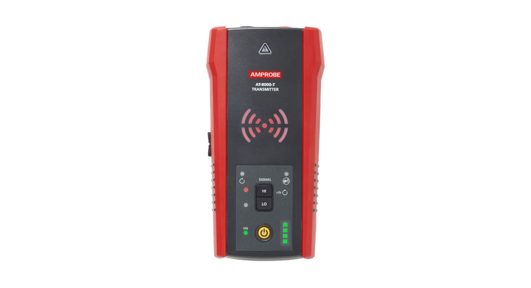
Quick Start GuideAT-8000 Advanced Wire Tracer
Reliable, precise breaker identificationTested by Fluke and safety certified by 3rd party labsIntuitive Transmitterautomatically senses whether the system is energized or de-energizedMost accurate wire tracingin its class with 10 sensitivity modes
AT-8000 Advanced Wire Tracer Special Applications:
- GFCI-protected circuit wire tracing
- Find breaks, openings, and shorts
- Trace wires in metal conduit: junction box method
- Trace non-metallic pipes and conduits
- Trace shielded wires
- Trace underground wires
- Trace low voltage wires and data cables
- Sort bundled wires
- Map circuits using test leads connection
- Trace breakers on a system with light dimmers
- CT-400 signal clamp (optional accessory) to improve accuracy and performance when there is no access to bare conductors
See the user manual for further instructions regarding special applications.
Tracing. Energized Wires – Smart Sensor TM
Set-up:1Test Leads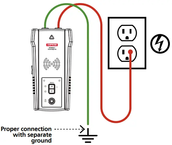
- Plug the green and red test lead into the Transmitter.
- Conned the green wire to a separate ground.
- Conned the red test lead to the wire being For receptacles, make sure to connect the test leads to the line (hot) wire. For Energized systems, the signal will ONLY be transmitted between the load-side to which the Transmitter is connected and the source of power.
Set-up:2Transmitter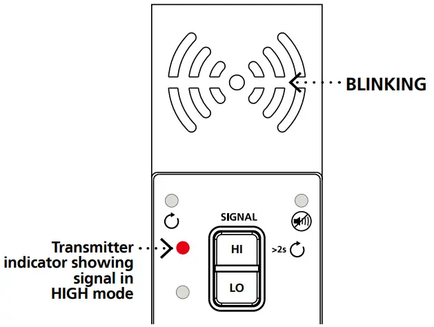
- Turn on the Transmitter.
- Verify that the test leads are properly connected; the red LED voltage status light should be on for circuits with voltage above 30 V AC/DC.
- Select HIGH signal mode by pressing HI.
Receiver:Energized Smart Sensor TM ModeThe Smart Sensor’ enables easier wire tracing by showing the direction and position of the wire and is the recommended method for tracing Energized wires.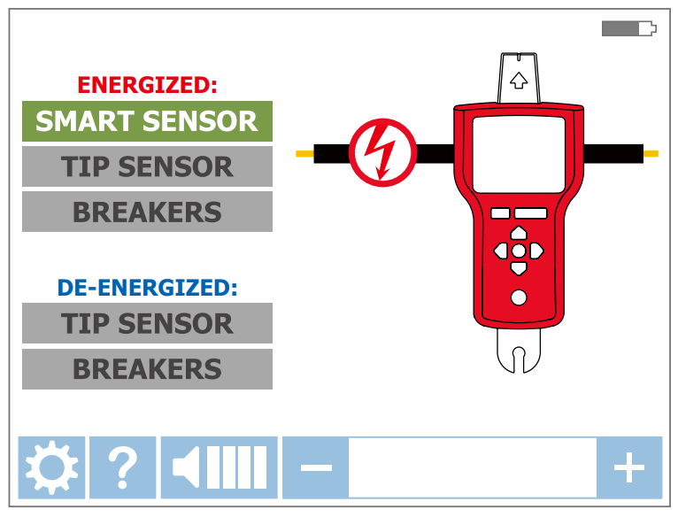
- Turn on the Receiver and select SMART SENSORTM mode using the directional arrows.
- Hold the Receiver with the Smart Sensor TM facing the target area.
- Move the Receiver in a direction indicated by the arrow on the screen. If the screen flashes a “?” in a red target then either no signal is detected or the signal is not adequate enough to display direction; increase the sensitivity using the “+” button on the
- Press ENTER when complete to return to the home screen.
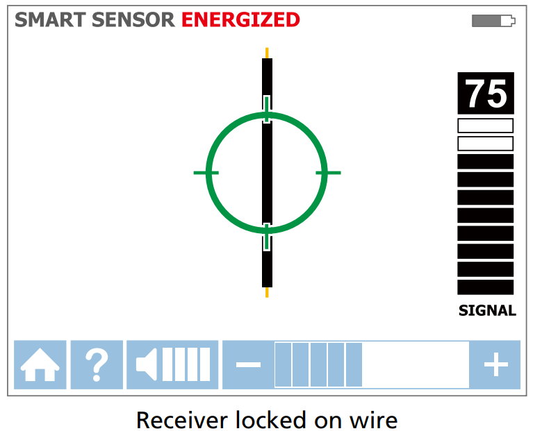
TIP: For best results, keep the Receiver at least 3 feet from the Transmitter and its test leads to minimize signal interference and improve wire tracing results. Select the “Long” Smart Sensor TM Range in the Settings Menu if working with wires that are greater than 3 feet deep.
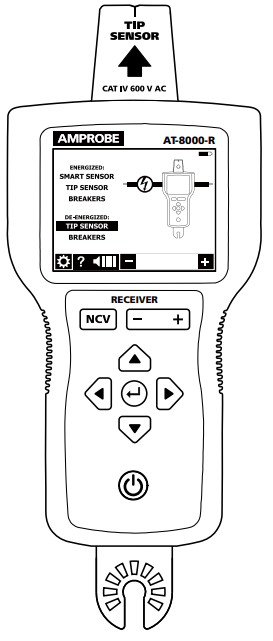
Tracing Energized and De-energized Wires – Tip Sensor
Set-up:1Test Leads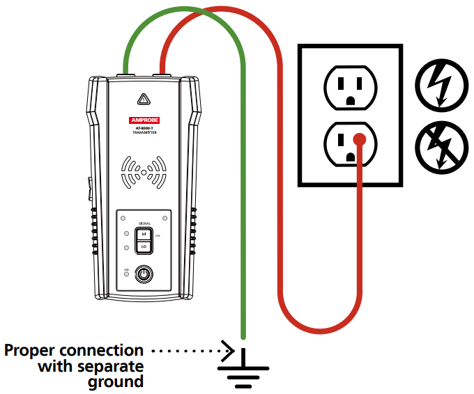
- Plug the green and red test leads into the Transmitter.
- Connect the green wire to a separate ground.
- Connect the red test lead to the wire being traced. For receptacles, make sure to connect the test lead to the line (hot) wire. For Energized systems, the signal will ONLY be transmitted between the load-side to which the Transmitter is connected and the source of power.
Set-up:2Transmitter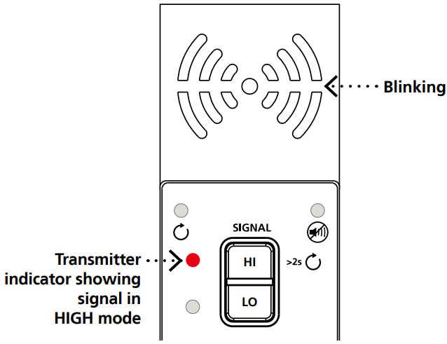
- Turn on the Transmitter.
- Verify that the test leads are properly connected; the red LED voltage status light should be on for circuits with voltage above 30 V AC/DC, and it should be off for De-energized circuits below 30 V AC/DC.
- Select HIGH signal mode by pressing HI.
Receiver:Energized and De-energized Tip Sensor ModesUse this mode for pinpointing a wire in a bundle or tracing in corners and confined spaces such as junction boxes and inside enclosures.
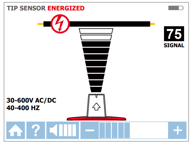
Receiver screen showing signal detected in Energized TIP SENSOR mode
- Turn on the Receiver and select either Energized or De-energized TIP SENSOR mode using the directional arrows.
- Hold the Receiver with the Tip Sensor facing the target area.
- Scan the target area with the Tip Sensor to find the highest signal level, then begin tracing the detected wire. Increase or decrease sensitivity of the Receiver by pressing + or – on the keypad as necessary.
- Press ENTER when complete to return to the home screen.
TIP: In Energized mode, align the groove on the Tip Sensor with the wire direction for best results; the signal may not be detected without this alignment.|De-energized mode uses a different antenna in the Tip Sensor than Energized mode. Specific alignment of the Tip Sensor groove to the wire is not required. De-energized wire tracing results are based only on how close the Tip Sensor is to the wire.
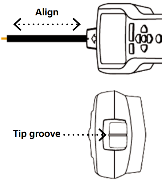
Aligning the Tip Sensor with the wire
Connecting Transmitter to an Energized Working System
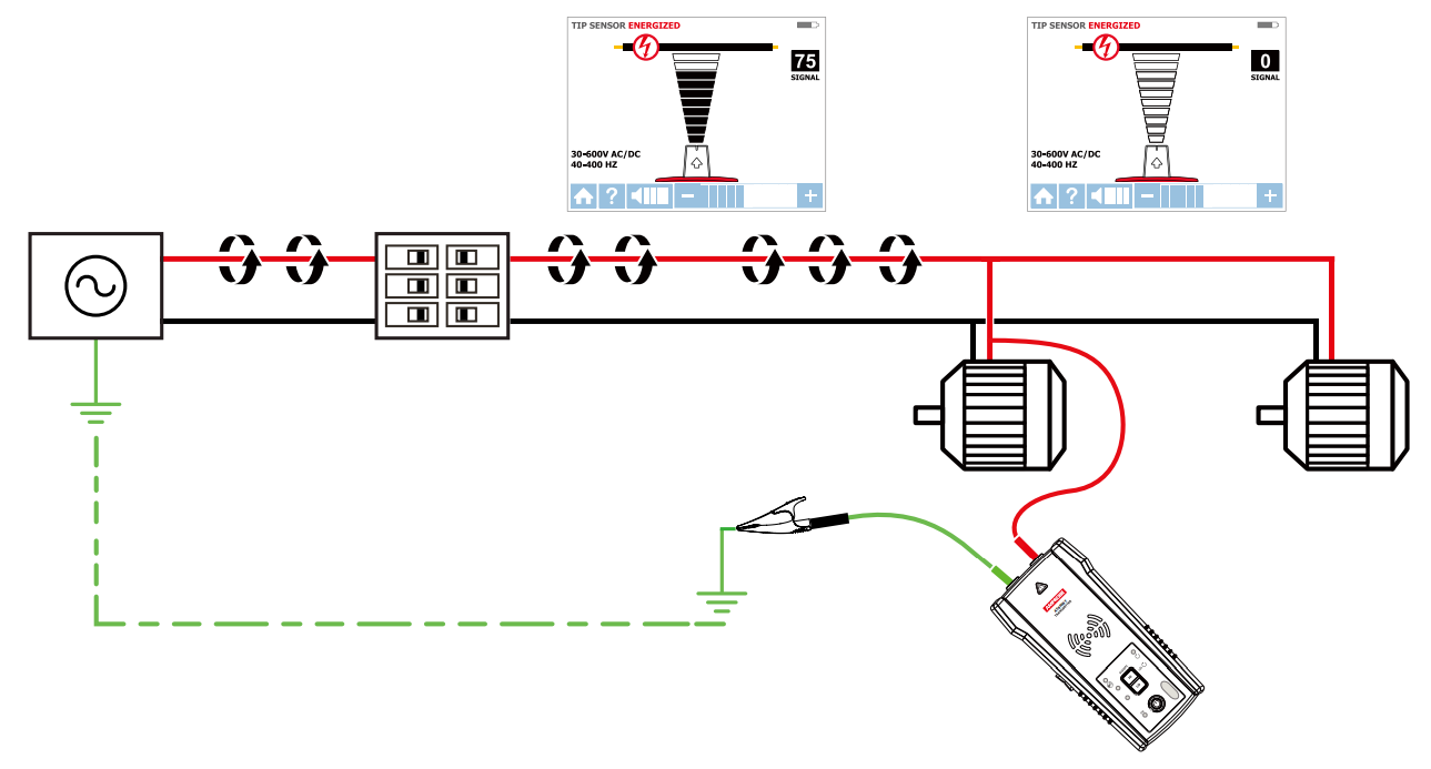
The Transmitter, with the red test lead, can be directly connected to the live wire of the working electrical equipment under load (motor, electronics, etc). Tracing can be performed without needing to turn off the equipment or switching power off.
Identifying Energized and De-energized Breakers and Fuses
Set-up:1Test Leads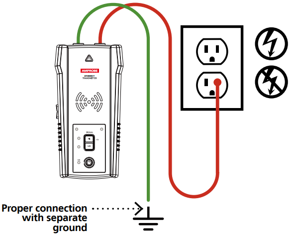
- Plug the green and red test leads into the Transmitter.
- Connect the green wire to a separate ground.
- Connect the red test lead to the wire being traced. For receptacles, make sure to connect the test leads to the line (hot) wire. For Energized systems, the signal will ONLY be transmitted between the load-side to which the Transmitter is connected and the source of power.
Note: Simplified direct connection can also be used to connect the Transmitter (refer to the user manual for further instructions).
Set-up:2Transmitter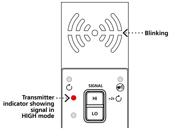
- Turn on the Transmitter.
- Verify that the test leads are properly connected; the red LED voltage status light should be on for circuits with voltage above 30 V AC/DC, and it should be off for De-energized circuits below 30 V AC/DC.
- Select HIGH signal mode by pressing HI.
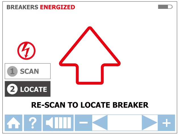
Receiver:Breakers ModeTracing breakers is a two-step process:
- SCAN – Scan each breaker for one second. The Receiver will record tracing signal levels.
- LOCATE – The Receiver will indicate the single breaker with the strongest recorded signal.
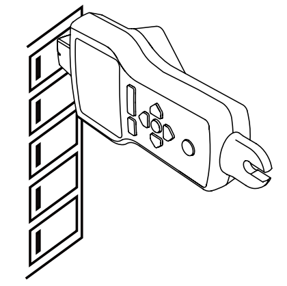
Correct alignment of the Tip Sensor to the breaker
Step 1 – 1 SCAN
- Turn on the Receiver and select either Energized BREAKERS mode or De-Energized BREAKERS mode using the directional arrows.
- Align the groove on the Tip Sensor with the breaker lengthwise.
- Scan each breaker by touching it with the Tip To assure sufficient time between the scans, wait for an active green arrow and audible alert before moving to the next breaker. The order of scanning does not matter. You can scan breakers multiple times. The Receiver records the highest detected signal.
Step 2 – 2 LOCATE
- Select LOCATE mode by using the directional arrows.
- Rescan each breaker by touching each with the Tip Sensor for one second. Active red arrow indicates the scanning process. Scan all breakers until solid green arrow and audible alert (continuous beep) indicates that the correct breaker was found.
- Press ENTER when complete to return to the home screen.
 |
|
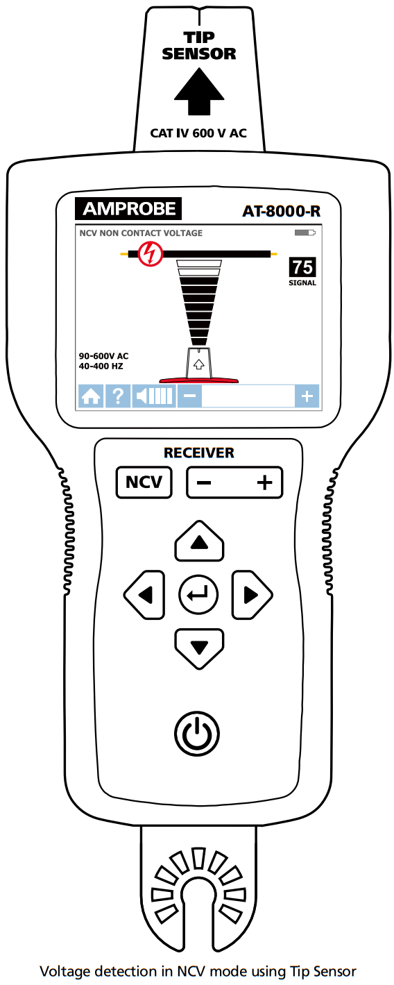
NCV Mode
Receiver:
The NCV (Non-Contact Voltage) mode is used to verify that a wire is Energized.This method does not require the use of the Transmitter.The Receiver will detect an Energized cable if the voltage is between 90 V and 600 V ACand between 40 Hz and 400 Hz. No current flow is necessary
- Turn on the Receiver and press the NCV button.
- Hold the Receiver with the Tip Sensor facing the target area.
- Scan the target area with the Tip Sensor to find the highest signal level, then begin tracing the detected For precise pinpointing of hot wire versus neutral wire, increase or decrease sensitivity by pressing + or – on the keypad.
- Press ENTER when complete to return to the home screen.
Note: For safety, before working with wires, always verify that they are De-energized with an additional tester.
Finding Breaks and Opens
Set-up:2 Transmitter
- Turn on the Transmitter.
- Verify that the test leads are properly connected; the red LED voltage status light should be off for De-energized circuits below 30 V AC/DC.
- Select HIGH signal mode by pressing HI.
Set-up:2 Receiver
- Turn on the Receiver and perform tracing in De-energized TIP SENSOR mode.
Tracing a cable to find breaks or opens
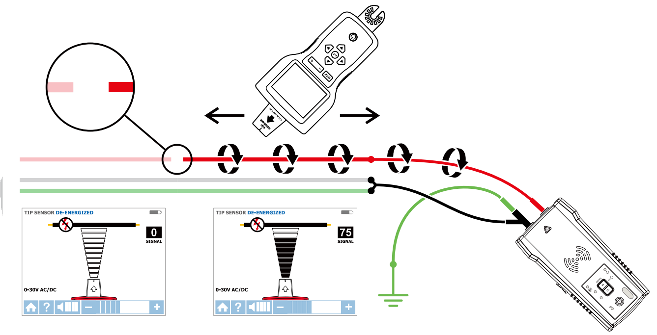
- Start tracing the cable until the signal stops.
- Verify the place of the fault: move the Transmitter to the other end of the wire and repeat tracing from the opposite end. If the signal stops at the exact same location the fault has been located.
Note: For best results, ground all De-energized wires that run in parallel with the black test lead.
Finding Shorts
Set-up:1 Transmitter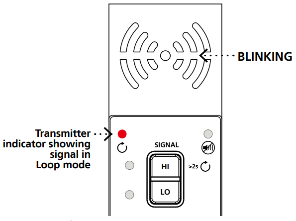
- Turn on the Transmitter.
- Verify that the test leads are properly connected; the red LED voltage status light should be off for De-energized circuits below 30 V AC/DC.
- Turn the Transmitter to Loop mode by pressing HIGH button for two seconds. Verify that the Loop LED is
Set-up:2 Receiver
- Turn on the Receiver and perform tracing in Energized TIP SENSOR mode.
Tracing a cable to find shorts
- Start tracing the cable until the signal stops.
- Verify the place of the fault: move the Transmitter to the other end of the wire and repeat tracing from the opposite end. If the signal stops at the exact same location the fault has been located.
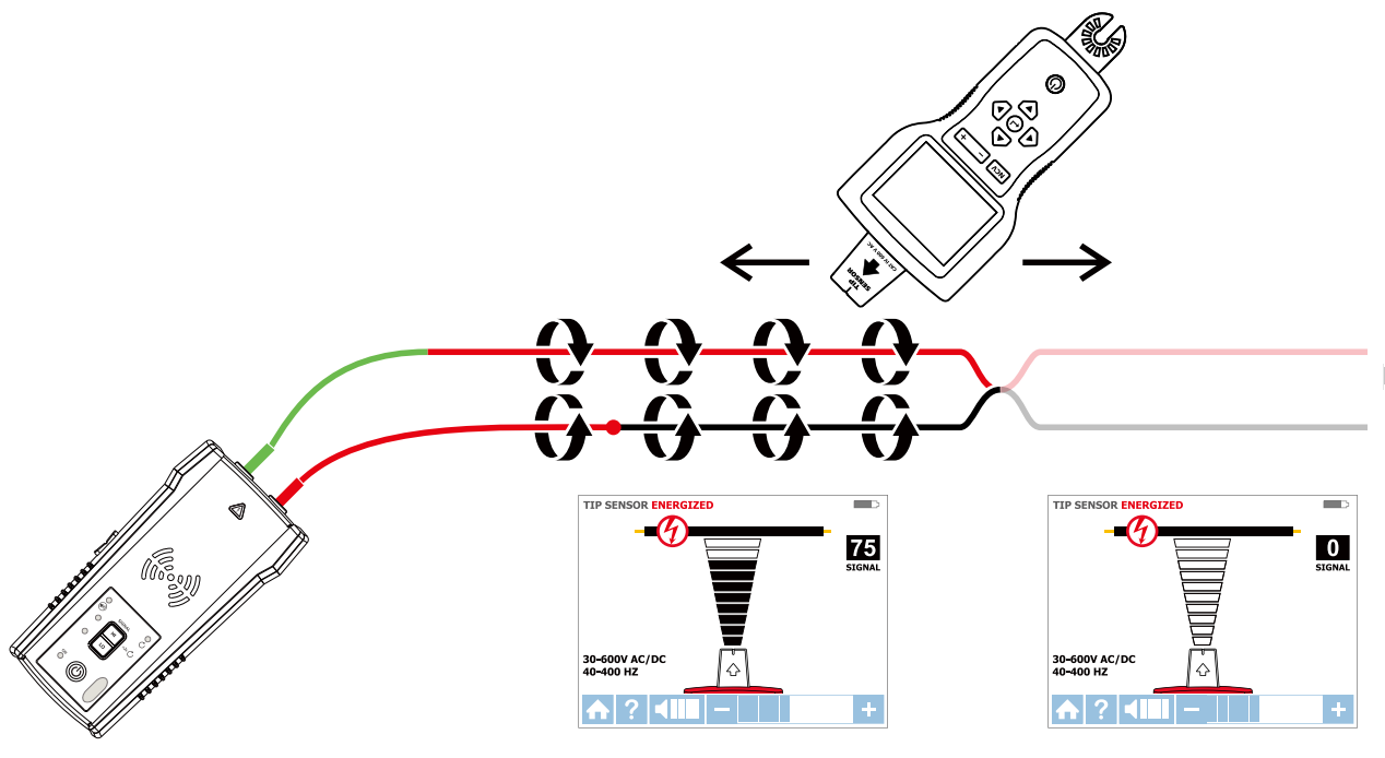
Note: This method will be affected by signal cancellation effect. Expect a relatively weak signal.
Specifications
| AT-8000-R Receiver | AT-8000-7 Transmitter | CT-400 Signal Clamp | |
| Measurement Category | CAT IV 600 V | CAT IV 600V | CAT IV 600 V,CAT III 1000V |
| Operating Voltage | 0 to 600 V AC/DC | 0 to 600 V AC/DC | 0 to 1000 VAC |
| Operating Frequency | Energized: 6.25 kHzDe-Energized: 32.768 kHz | Energized/Loop: 6.25 kHzDe-Energized: 32.768 kHz | loop Mode:6.25 kHzHigh /LowMode: 32.768 kHzAC current measurement:45 Hz to 40D Hz |
| Hazardous Voltage Detection | See NCVdetection | > 30 VACJDC | WA |
| Signal Indications | Numeric bar graph display and audible beep | LEDs and au dble beep | N/A |
| Response Time | Smart mode: 750 mSecTip Sensor Energized: 300 mSecTip Sensor De-Energized: 750 mSecNCV: 500 mSecBattery monitoring: 5 Sec | Uneiphae voltage monitoring. 1 secBattery voltage monitoring: S sec | Instantaneous
|
| Current Output of Signal (typical) | N/A | Energized circuit: HI mode: 60 mA RMS LO mode: 30 mA RMS De-energized circuit: HI mode: 130 mA RMS LO mode: 40 mA RMS Loop mode: 160 mA RMS | 1 mA/A for AC current measurementwith mu kimeter |
| Signal Voltage Output (nominal) | N/A | De-energized drcultLOW: 29 VAMS, 120 Vp-pHIGH: 33 V RMS, 140 Vp-pLoop model: 31 V RMS, 120 Vp-p | De-energized circuit:2.4 V RMS, 24 Vp-p |
| Range Detection (open air) | Smart modePinpointing: Around 1.97-in (5 cm) radius(*2%)Direction indication: Up to 5FT (152.4cm) (t2%)TIP Sensor. EnergizedPinpointing: Around 1.97-in (5 cm)(s1%)Detection: Up to 22-FT(670.5Ecm) (*1%)TIP Sensor: De–EnerglzedDetection: Up to 14- FT(426.72cm) (*5%)NCV (40-400 Hz)Pirpointing: Around 1.97-in (5cm) radius (*5%)Detection: Unto 4FT(121.92cm)(t 5%) | N/A | N/A |
| Display Size | 3.5 in (89 mm) | LEDs | N/A |
| Display Dimensions (W x H) Display | 2.76 x 2.07 in (70x 52 mm) | WA | N/A |
| Display Type | 320 x 240 | WA | N/A |
| Display Color | yes | Operating mode LEDs: redBatten/status LEDs: green, yellow, red | N/A |
| Booting Time
|
yes | /A | N/A |
| Backlight
|
30 sec | <2 sec | N/A |
| Operating Temperature | -4 °F to 122 °F (-20 °C to 50 °C) | -4 °F to 122 °F (-20 °C to 50°C) | 32 °F to 122 °F (0 °C to 50 °C) |
| Operating Humidity | 45%: -4 °F to <SO °F (-20 °C to <10 °C) 95%:50 °F to <86 °F (10 °C to <30 °C) 75%: 86 °F to <104 °F (30 °C to <40 °C) 45%: 104 °F to 122 °F (40 °C to SO °C) | 45%: -4 °F to <50 °F (-20 °C to <10 °C) 95%: 50 °F to <86 °F (10 °C to <30 °C) 75%: 86 °F to <104 °F (30 °C to <40 °C) 45%: 104 °F to 122 °F (40 °C to 50 °C) | 95%: 50 °F to <86 °F (10 °C to <30 °C)75%: 86 °F to <104 °F (30 °C to <40 °C)45%: 104 °F to <122 °F (40 °C to <50 °C) |
| Storage Temperature Humidity | -4 °F to 158 °F (-20 °C to 70 °C),
<95% RH |
-4 °F to 158 °F (-20 °C to 70 °C),<95% RH | -4 °F to 140 °F (-20 °C to 60 °C),<95% RH |
| Operating Altitude | 0 to 6561 ft (2000 m) | ||
| Transient Protection | WA | 8.00 kV (1.2/50pS surge) | N/A |
| Pollution Degree | 2 | ||
| IP Rating | IP 52 | IP 40 | |
| Drop Test | 3.28 ft (1 m) | ||
| Power Supply | 4 x AA (alkaline or NiMH rechargeable) | 8 x AA (alkaline or NiMH rechargeable) | WA |
| Power Consumption (typical | 4 x AA battery: 2W | HVLo mode: 70 mALoop mode with Clamp: 90 mAConsumption without signaltransmission: 10 mA | N/A |
| Battery Life (typical) | Approx. 9 h | Hi/Lo mode: approx. 25 hLoop mode: approx. 18 h | WA |
| Low Battery Indication | yes | yes | N/A |
| Fuse | WA | 1.6 A, 700 V, fast-acting, 0 6x32mm | WA |
| Maximum Conductor Size | WA | N/A | 1.26 in (32 mm) |
| Dimensions IL x ‘1Y x H: | Approx. 10.92 x 4.43 x 2.55 in
|
Approx. 7.2 x 3.66 x 1.97 in(183 x 93 x 50 mm) | Approx. 5.9 x 2.75 x 1.18 in(150 x 70 x 30 mm) |
| Weight (batteries installed) |
Approx. 1.20 lb (0.544 kg) |
Approx. 1.25 lb (0.57 kg) |
Approx. 0.25 lb (0.114 kg) |
| certifications |  |
 |
Accessory Specifications
| TL-8000-INT | |
| Measurement Category | CAT IV 600 V (test leads)CAT IV 600 V (alligator clips)CAT II 300 V (outlet adapters) |
| Operating Voltage and Current | 1000 V, 16 A max. (red/green leads)600 V, 16 A max. (black lead)600 V, 10 A max. (alligator clips)300 V, 10 A max. (outlet adapters) |
| Operating Temperature | 32 °F to 122 °F (0 °C to 50 °C) |
| Operating Humidity | 95%: 50 °F to <86 °F (10 °C to <30 °C)75%: 86 °F to <104 °F (30 °C to <40 °C)45%: 104 °F to <122 °F (40 °C to <50 °C) |
| Storage Temperature and Humidity | -4 °F to 140 °F (-20 °C to 60 °C), <95% RH |
| Operating Altitude | 0 to 6561 ft (2000 m) |
| Pollution Degree | 2 |
| IP Rating | IP 20 |
| Drop Test | 3.28 ft (1 m) |
| Dimensions | Red/black leads: 3.28 ft (1 m)Green lead: 22.97 ft (7 m)Alligator clips: approx. 3.74 x 1.77 x 0.94 in (95 x 45 x 24 mm)Outlet adapters: 2.83 x 0.71 x 0.71 in (72 x 18 x 18 mm) |
| Weight | Approx 0 88 lb (0.4 kg) |
| Certifications |
Included in Wire Tracer Kits
| AT-8020 KIT | AT-8030 KIT | |
| AT-8000-R RECEIVER | 1 | 1 |
| AT-8000-T TRANSMITTER | 1 | 1 |
| TL-8000-INT TEST LEAD AND ACCESSORY KIT* | 1 | 1 |
| CC-8000 HARD CARRYING CASE | 1 | 1 |
| USER MANUAL | 1 | 1 |
| BATTERY CHARGERS | – | 3 |
| RECHARGEABLE BATTERIES | – | 12 |
| CT-400 SIGNAL CLAMP | – | 1 |
| HS-1 MAGNETIC HANGER | – | 1 |
| 1.5 V AA (IEC R6) BATTERIES | 12 | – |
*T1-8000-INT test lead and accessory kit includes:
- 2 x 1 m test leads (red, black)
- 1 x 7 m test lead (green)
- 2 x Alligator clips (red, black)
- 2 x Outlet blade adapter (red, black)
- 2 x Outlet round adapter (red, black)
Optional accessories:
ADPTR-SCT Socket adapter HS-1 Magnetic hangerTL-8000-25M Test leadCT-400 Signal clamp
Test Equipment Depot – 800.517.8431 – 99 Washington Street Melrose, MA 02176 TestEquipnnentDepot.corn
 |
99 Washington StreetMelrose, MA 02176Phone 781-665-1400Toll-Free 1-800-517-8431 |
 report this ad
![]() Visit us at www.TestEquipmentDepot.com
Visit us at www.TestEquipmentDepot.com
References
[xyz-ips snippet=”download-snippet”]