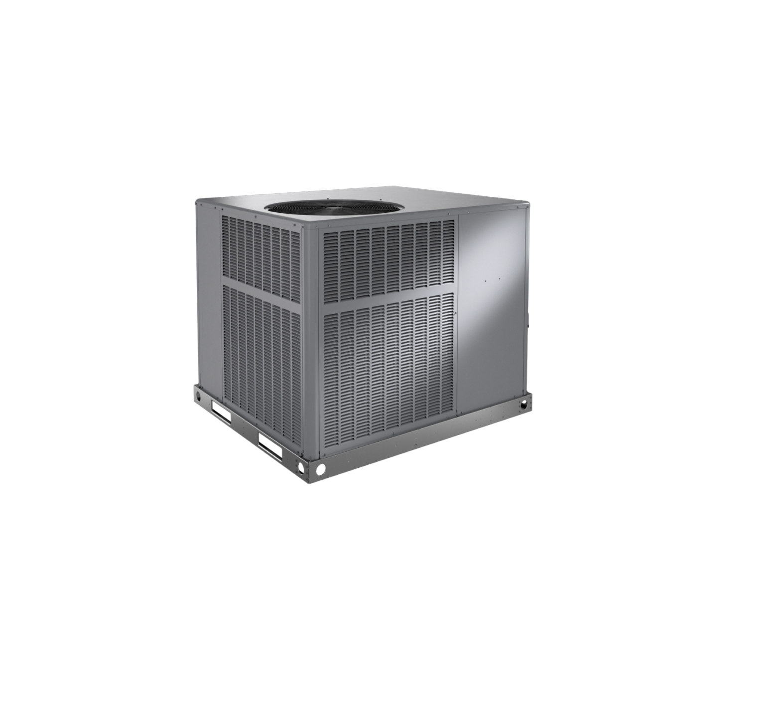
507296-03 Residential Packaged Units Air Conditioners and Heat Pumps
INSTALLATION AND MAINTENANCE INSTRUCTIONS*RP14AC AND *RP14HP SERIES UNITSRESIDENTIAL PACKAGED UNITSAir Conditioners and Heat Pumps 507296-03 12/2020
THIS MANUAL MUST BE LEFT WITH THE HOMEOWNER FOR FUTURE REFERENCEWARNINGInstallation and servicing of air conditioning equipment can be hazardous due to internal refrigerant pressure and live electrical components. Only trained and qualified service personnel should install or service this equipment. Installation and service performed by unqualified persons can result in property damage, personal injury, or death.
Table of ContentsUnit Dimensions ………………………………………………….2 Roof Curb Dimensions …………………………………………4 Adjustable Roof Curb Dimensions………………………….6 Installation ………………………………………………………….8 Electrical Wiring…………………………………………………10 Duct System …………………………………………………….. 11 Filters ………………………………………………………………. 11 Condensate Drain………………………………………………12 Sequence of Operation……………………………………….12 Maintenance ……………………………………………………..15 Wiring Diagrams ………………………………………………..18
WARNINGFor your safety, do not store or use gasoline or other flammable vapors and liquids in the vicinity of this or any other appliance. Such actions could result in property damage, personal injury, or death.
WARNINGIf this unit is to be installed in a mobile or manufactured home application, the duct system must be sized to achieve static pressures within the manufacturer’s guidelines. All other installation guidelines must also be followed. Failure to do so may result in equipment damage, personal injury, and improper performance of the unit.
215 Metropolitan Drive West Columbia, SC 29170
*P507296-03*(P) 507296-03
CAUTIONThe installation of this appliance must conform to the requirements of the National Fire Protection Association; the National Electrical Code, ANSI/NFPA No. 70 (latest edition) in the United States; the Canadian Electrical Code Part 1, CSA 22.1 (latest edition) in Canada; and any state or provincial laws or local ordinances. Local authorities having jurisdiction should be consulted before installation is made. Such applicable regulations or requirements take precedence over the general instructions in this manual.
507296-03
Save these instructions for future referenceIssue 2107
Page 1 of 19
Unit Dimensions – Small Base Air Conditioners & Heat Pumps
47.66
2.48
1.98
2.33
2.33
16.77
14.02
TOP VIEW
11.49
RETURN AIR
SUPPLY AIR
11.49
18.52 16.07
47.66 SIDE VIEWS
POWER ENTRY POWER ENTRY
3.2520.31 21.06 23.19
6.94 4.56
13.44
13.44
14.326.20 3.07Page 2 of 19
5.86
40.89
CONDENSATE DRAIN 3/4 NPT
21.63
13.21TYPICAL DRAIN LOCATION
3.87 3.62
17.07
34.19 29.59
12.12 6.20
Issue 2107
POWER ENTRY 1-1/8 DIA. KNOCKOUTLOW VOLTAGE ENTRY 7/8 DIA. KNOCKOUT
ELECTRIC HEAT POWER ENTRY4.06
507296-03
Unit Dimensions – Large Base Air Conditioners & Heat Pumps
56.13
2.33
2.11
2.39
19.49
19.49
TOP VIEW
11.49
RETURN AIR
SUPPLY AIR
2.33
11.49
18.52 16.07
47.66 SIDE VIEWS
POWER ENTRY POWER ENTRY6.94 3.2510.06 25.81 26.56 28.68
18.19
18.19
14.32
6.20 507296-03
3.76
4.20
44.89
CONDENSATE DRAIN 3/4 NPT
21.63
13.21TYPICAL DRAIN LOCATION
3.87
17.07
3.62 4.06 33.59 38.19
12.14
6.20
Issue 2107
POWER ENTRY 1-1/8 DIA. KNOCKOUT LOW VOLTAGE ENTRY 7/8 DIA. KNOCKOUTELECTRIC HEAT POWER ENTRYPage 3 of 19
Roof Curb Dimensions – Small Base Air Conditioners & Heat Pumps
3/4 (19)
Opening for Power Entry Through Unit Base
RETURN OPENING
5-1/2 x 5-5/8 in.
(140 x 31 mm)
44-3/8 (1127)
11-1/2
16-7/8 (429)
2-1/8
Insulated
(287)
(54)
Panels
5-3/4
1
(146) (25)
5-1/2
(140)
SUPPLY OPENING
13-7/8 (352)
8 (203) 14 (356)
17-1/4
11-1/2 18 (457)
(438)
(287) 24 (610)
3
44-3/8 (1127)
(76)
1-3/8
13 (35)
(330)
Opening for Power Entry Through Unit Base 3 x 13 in. (76 x 330 mm)
3-3/4 (95)
NOTE – Roof deck may be omitted within confines of curb.
Page 4 of 19
Issue 2107
507296-03
Roof Curb Dimensions – Large Base Air Conditioners & Heat Pumps
Opening for Power Entry Through Unit Base 5-1/2 x 5-5/8 in. (140 x 31 mm)
44-3/8 (1127)
Insulated Panels
3/4 (19)
19-1/2
11-1/2
(380)
1
(287) (25)
RETURN OPENING
2-1/8 (54)19-1/2
(380)
SUPPLY
OPENING 11-1/2
22-7/8
(287)
(581)
52-7/8 (1343)Opening for Power Entry Through Unit Base 3 x 13 in. (76 x 330 mm)
3-3/4 (95)
7 (178)
8 (203) 14 (356) 18 (457) 24 (610)
NOTE – Roof deck may be omitted within confines of curb.
507296-03
Issue 2107
Page 5 of 19
Adjustable Roof Curb Dimensions – Small Base Air Conditioners & Heat PumpsCLIPLOCK CORNER DETAILTop Edge Wood Nailer Strip
CURB PROFILE1 1/21-3/4 Opening for Power Line Entry thru base44-3/8 Insulated Panels44-3/8
Bottom FlangeTypical Slot Typical Locking TabNOTE: See Cliplock 1000 installation instructions for complete assembly and installation procedures and requirements.1
11-5/8
16-7/8
1
5-3/4
5-1/2
3-1/2
13-1/2
17-1/4
3-5/8
1-3/8
2-1/8 13-7/814 11-5/8
Page 6 of 19
Bottom Curb AssemblyOpening for Power Entry thru base
NOTE – Roof deck may be omitted within confines of curb.Issue 2107
507296-03
Adjustable Roof Curb Dimensions – Large Base Air Conditioners & Heat PumpsCLIPLOCK CORNER DETAILTop Edge Wood Nailer Strip
CURB PROFILE1 1/21-3/4 Opening for Power Line Entry thru base44-3/8 Insulated Panels52-7/8
Bottom FlangeTypical Slot Typical Locking TabNOTE: See Cliplock 1000 installation instructions for complete assembly and installation procedures and requirements.1
11-5/8
19-5/8
5-1/2
1 5-3/4
23-1/8
3-1/2
13-1/2
3-1/2
6-7/8
2-1/8 19-3/811-5/8 14
Bottom Curb AssemblyOpening for Power Entry thru base
507296-03
NOTE – Roof deck may be omitted within confines of curb. Issue 2107
Page 7 of 19
WARNINGImproper installation, adjustment, alteration, service, or maintenance can cause injury or property damage. Refer to this manual. For assistance or additional information, consult a qualified installer or service agency.InstallationThese instructions explain the recommended method of installation of the packaged heat pump and air conditioner units and associated electrical wiring.This unit is designed and approved for use as a selfcontained air-to-air outdoor heat pump and air conditioner system.The units are factory-equipped with a transformer and blower control for applications without auxiliary heat. Electric heat accessory kits (PHK-) can be ordered for field installation of additional heat where required.These instructions, and any instructions packaged with mating components and/or accessories, should be carefully read prior to beginning installation. Note particularly any CAUTIONS or WARNINGS in these instructions and all labels on the units.These instructions are intended as a general guide only, for use by qualified personnel and do not supersede any national or local codes in any way. Compliance with all local, state, provincial, or national codes pertaining to this type of equipment should be determined prior to installation.Inspection of Shipment Upon receipt of equipment, carefully inspect it for possible shipping damage. If damage is found, it should be noted on the carrier’s freight bill. Take special care to examine the unit inside the carton if the carton is damaged. File a claim with the transportation company.If any damages are discovered and reported to the carrier, DO NOT INSTALL THE UNIT, as claim may be denied.Check the unit rating plate to confirm specifications are as ordered.Limitations The unit should be installed in accordance with all national and local safety codes.Limitations of the unit and appropriate accessories must also be observed.The unit must not be installed with any ductwork in the outdoor air stream. The outdoor fan is not designed to operate against any additional static pressure.
Location The unit is designed to be located outdoors with sufficient clearance for free entrance to the air inlet and discharge air openings. The location must also allow for adequate service access.The unit must be installed on a solid foundation that will not settle or shift. Adequate structural support must be provided. Install the unit in level position. Isolate the base from the building structure to avoid possible transmission of sound or vibration into the conditioned space.The heat pump unit foundation should be raised to a minimum of 3″ above finish grade. In areas that have prolonged periods of temperature below freezing and snowfall, the heat pump unit should be elevated above the average snow line. Extra precaution should be taken to allow free drainage of condensate from defrost cycles to prevent ice accumulation. The unit should not be located near walkways to prevent possible icing of surface from defrost condensate.Avoid placing the unit near quiet areas, such as sleeping quarters or study rooms. Normal operating sound levels may be objectionable if the unit is placed near certain rooms.For improved start-up performance, the condenser coil should be washed with suitable detergent to remove any residue from manufacturing processes.Use of Unit During Construction Use of this unit as a construction heater or air conditioner is not recommended during any phase of construction. Very low return air temperatures, harmful vapors and operation of the unit with clogged or misplaced filters will damage the unit.If this unit has been used for heating or cooling of buildings or structures under construction, the following conditions must be met or the warranty will be void:· A room thermostat must control the unit. The use of fixed jumpers that will provide continuous heating or cooling is not allowed.· A pre-filter must be installed at the entry to the return air duct.· The return air duct must be provided and sealed to the unit.· Return air temperature range between 55°F (13°C) and 80°F (27°C) must be maintained.· Air filters must be replaced and pre-filters must be removed upon construction completion.· The input rate and temperature rise must be set per the unit rating plate.· The heat exchanger, components, duct system, air filters and evaporator coil must be thoroughly cleaned following final construction clean-up.
Page 8 of 19
Issue 2107
507296-03
· The unit operating conditions (including airflow, cooling operation, ignition, input rate, temperaturerise and venting) must be verified according to these installation instructions.
Clearances All units require certain clearances for proper operation and service. Refer to Table 1 for the minimum clearances to combustibles required for construction, servicing, and proper unit operation.In the U.S., units may be installed on combustible floors made from wood or class A, B, or C roof covering material.In Canada, units may be installed on combustible floors. Units must be installed outdoors.Do not permit overhanging structures or shrubs to obstruct condenser air discharge outlet.
Front of unit
Clearance to Combustibles0 in.
Clearance for Service Access24 in.
Back of unit
0 in.
Left side
0 in.
Right side
0 in.
0 in. 24 in. 24 in.
Base of unit
0 in.
0 in.
Top of unit
0 in.
48 in.
For any future service, installer must provide access to screws of top and rear panels.
Table 1. Minimum Clearances
Compressor Units are shipped with compressor mountings factory adjusted and ready for operation. Do not loosen compressor mounting bolts.Roof Curb Installation If a roof curb is used, follow the manufacturer’s installation instructions and be sure that all required clearances are observed (see Clearances section).Prior to setting the unit on the roof curb, the shipping bracket located underneath the unit must be removed. Remove the two screws in the base rail (located on the front and rear sides of the unit). The four screws and the bracket can be discarded. See Figure 1.Rigging Unit Exercise care when moving the unit. Do not remove any packaging until the unit is near the place of installation.1. Connect rigging to the unit base rails using both holes in each corner.2. All panels must be in place for rigging. 3. Place field-provided spreaders in place. Spreadersmust be of adequate strength and length (must exceed unit dimension by 6 inches).Units may also be moved or lifted with a forklift. The lengths of the forks of the forklift must be a minimum of 42 inches.
Field-Provided Lifting Spreaders Recommended
507296-03
Shipping Bracket and Mounting Screws Must be Removed for Rooftop or Downflow ApplicationFigure 1.Issue 2107
Page 9 of 19
CAUTIONBefore lifting a unit, make sure that the weight is distributed equally on the cables so that it will lift evenly.High Voltage Power Entry Thermostat Wire EntryGas EntryFigure 2.Unpacking Locate the four stacking brackets at each corner of the top panel. Remove the screws and washers that secure these brackets. All screws must be re-installed. The washers and stacking brackets can be discarded. Remove the bag and remaining packaging material, which can be discarded. Locate the four plastic fork slot bumpers on the base rails. Remove the fasteners and bumpers and discard.CAUTIONAs with any mechanical equipment, personal injury can result from contact with sharp sheet metal edges. Be careful when you handle this equipment.Service Access Access to all serviceable components is provided by four removable panels: upper access panel (for blower, ID coil, and optional filter), auxiliary heat access, control access panel, and compressor access.
Electrical WiringAll field wiring must be done in accordance with National Electrical Code recommendations, local codes, and applicable requirements of UL Standards, or in accordance with Canadian Electrical Code recommendations, local codes, or CSA Standards. Power wiring, disconnect means, and over-current protection are to be supplied by the installer. Refer to the unit rating plate for maximum over-current protection and minimum circuit ampacity, as well as operating voltage. The power supply must be sized and protected according to specifications supplied.The unit must be grounded with a separate ground conductor. See Figure 4 for typical field wiring connection. The wiring diagram can be found on the unit inside the access panel. Low voltage control wiring are terminal strip or pigtail leads located on the main control box and are color-coded to match the connection called out on the wiring schematic.NOTE: An optional bottom-entry power kit is available for these units. See the kit instructions for proper installation details.
CAUTIONWhen connecting electrical power and control wiring to the unit, waterproof-type connectors must be used so that water or moisture cannot be drawn into the unit during normal operation.
Units are factory wired for a 230-volt power supply. If power supply is 208 volts, it will be necessary to change a wire connection on the unit transformer from 240V terminal to 208V terminal as shown on the wiring diagram.Use only copper conductors.If any of the original unit wiring is replaced, the same size and type wire must be used.
Contactor
Ground Lug
Field-Supplied Fused or Circuit Breaker Disconnect
Single Phase Power Supply
WARNINGThis unit is charged with HFC-410A refrigerant. Operating pressures for units charged with HFC-410A are higher than pressures in units charged with HCFC22. All service equipment MUST be rated for use with HFC-410A refrigerant.
If 208 Volt is supplied, transformer connection must be changedFigure 3. 208/230 Line Voltage Wiring
Page 10 of 19
Issue 2107
507296-03
! CAUTION Do not connect C connections except when required by the indoor thermostat. Refer to thethermostat installation instructions.
Thermostat The room thermostat should be located on an inside wall where it will not be subject to drafts, sun exposure, or heat from electrical fixtures or appliances. Follow the manufacturer’s instructions enclosed with the thermostat for general installation procedure. Color-coded insulated wires (#18 AWG) should be used to connect the thermostat to the unit. A minimum of five wires are required for proper installation.
THERMOSTAT R C Y1 O W G
OUTDOOR UNIT R Red C Blue Y1 Yellow* O OrangeW White G Green
*”O” connection used only on heat pump models SINGLE PHASE
L2
L1
GROUND
SCREW
The supply and return air duct systems should be designed for the CFM and static requirements of the job. They should not be sized to match the dimensions of the duct connections on the unit.The unit is shipped ready for horizontal flow (side duct connections) or downflow (bottom duct connections). All units are equipped with a drain pan overflow switch that is installed and wired at the factory. Duct attachment screws are intended to go into the duct panel flanges. Duct to unit connections must be sealed and weather proofed.For horizontal duct systems:1. Remove the duct covers on side of the unit. They can be discarded.2. Install the duct system to the unit.For downflow duct systems:1. Remove the duct covers on side of the unit. Keep the screws and the covers as they will be re-installed later.2. Remove the downflow duct covers located inside unit. Remove the four screws securing each cover. Remove the covers from the unit. They can be discarded.3. Remove screws located between the supply and return air openings that attach the blower deck to the base pan. These screws can interfere with bottom duct connections or roof curb seals. Discard these screws.4. Install the duct system to the unit.5. Re-install the duct covers removed in Step 1.
POWER WIRING 208/230-1-60(75° MIN. WIRE) POWER WIRING 24V CONTROL WIRING(NEC CLASS 2)W1, W2 can be used to stage electric heat accessory on 10, 15 & 20 kW models. 5 And 7 kW heater accessory function off W1 only.Figure 4. Typical Wiring ConnectionsDuct SystemThe duct system should be designed and sized according to the methods in the Air Conditioning Contractors of America (ACCA) manual that is most appropriate to the installation application.A closed return duct system shall be used. This shall not preclude use of economizers or outdoor fresh air intake. It is recommended that supply and return duct connections at the unit be made with flexible joints.
FiltersAir filters are not supplied with the unit. A field-provided air filter must always be installed ahead of the evaporator coil and must be kept clean or replaced. Dirty filters will reduce the airflow of the unit.An optional filter rack kit may be purchased separately for installation inside the unit’s coil compartment. Air filter sizes are shown in Table 2 for use with filter rack kit.
NOTE:The filter rack must be installed prior to installation of the unit in applications where access to the rear panel is limited.
Unit Model 24,30,36 42,48,60
Filter 1 14 x 20 x 1 20 x 20 x 1
Filter 2 20 x 20 x 1
Table 2. Unit Air Filter Sizes – inches
507296-03
Issue 2107
Page 11 of 19
Condensate DrainThis package unit is equipped with a 3/4″ FPT coupling for condensate line connection. Plumbing must conform to local codes. Use a sealing compound on male pipe threads.Do not operate unit without a drain trap. The condensate drain is on the negative pressure side of the blower; therefore, air being pulled through the condensate line will prevent positive drainage without a proper trap.The condensate drain line must be properly trapped, routed to a suitable drain and primed prior to unit commissioning.NOTE: Install drain lines and trap so they do not block service access to the unit.See Figure 5 for proper drain arrangement. The drain line must pitch to an open drain or pump to prevent clogging of the line. Seal around the drain connection with suitable material to prevent air leakage into the return air system.To prime trap, pour several quarts of water into drain, enough to fill drain trap and line.CAUTIONDrain lines should be hand-tightened only. Do not use tools to tighten fitting into drain.
Minimum Pitch:
1 in (25) Per 10″
(3048 mm) of
Unit
Line
Open Vent
Crankcase Heater (if used) Some models may be equipped with a crankcase heater to prevent excessive migration of liquid refrigerant into the compressor during off cycles. Power must be maintained to the unit to keep this feature active.Except as required for safety while servicing, do not open the system disconnect switch.Heater Kit Accessory (if used) The unit is fully equipped for cooling operation without auxiliary heat. A heater kit accessory may also be used. To install the heater kit accessory (see Figure 7):1. Disconnect the power and open the main control access.2. Disconnect the plug separating the high voltage wire harness. Remove the high voltage wire harness plug and discard.3. Remove the heater blockoff by removing the four screws holding it in place.4. Insert the heater into the control panel and fasten in the same mounting holes.5. Plug the heater wiring harness into the wire harness on the control assembly. Field wiring of the auxiliary heater is separate from the unit power supply. Wire the power supply wiring for the heater to the appropriate connections on the heater kit.Sequence of OperationCooling When the thermostat is in the cooling mode, the O circuit is powered, which energizes the reversing valve. Upon cooling demand, the thermostat closes circuit R and Y. Closing R and Y closes the unit contactor, starting the compressor and outdoor fan. The thermostat automatically closes the R to G circuit, which brings on the indoor blower at the same time. Upon satisfying cooling demand, the thermostat will open the above circuits and open the main contactor, stopping the compressor and outdoor fan. If the unit is equipped with a delay timer, the blower will continue to operate for 60 to 90 seconds, which improves system efficiency.
Mounting FrameTrap must be deep enough to offset maximum static difference (generally, 3 inches (76 mm) minimum). In addition, the drain line must be supported if longer than 10 feet.Trap must be primed at start-up.Figure 5. Typical Condensate Drain Connection
Heating – Heat Pump Stage Upon heating demand, the thermostat closes circuit R to Y, which closes the unit contactor, starting the compressor and outdoor fan. The reversing valve is not energized in the heating mode. The thermostat again automatically brings on the indoor fan at the same time. Upon satisfying heating demand, the thermostat opens above circuits and stops unit operation.Heating – Auxiliary Electric Heat Upon heating demand for auxiliary electric heat, the thermostat closes circuit R to W, which energizes the
Page 12 of 19
Issue 2107
507296-03
heater sequencers as well as the indoor blower. Upon satisfying auxiliary heat demand, the thermostat opens above circuits and heating elements sequence off; blower continues to operate until all heating elements have turned off.Defrost System The defrost system includes two components: the defrost thermostat and the defrost control.Defrost ThermostatThe defrost thermostat is located on the evaporator coil. When the defrost thermostat senses 35°F or cooler, the thermostat contacts close and send a signal to the defrost control board to start the defrost timing. It also terminates defrost when the liquid line warms up to 60°F.Defrost ControlThe defrost control board includes the combined functions of time/temperature defrost control, defrost relay, diagnostic LEDs and terminal strip for field wiring connections (see Figure 6).The control provides automatic switching from normal heating operation to defrost mode and back. During the compressor cycle (call for defrost), the control accumulates compressor run time at 30, 60, 90 minute field-adjustable intervals. If the defrost thermostat is closed when the selected compressor run time interval ends, the defrost relay is energized and the defrost begins.
DEFROST TIMING PINS (P1)TEST PINSCOMPRESSOR DELAY PINS REVERSING VALVES87LOW PRESSURE SWITCHDEFROST THERMOSTAT (S6)S4HIGH PRESSURE SWITCH
DIAGNOSTIC LEDS24V TERMINAL STRIP CONNECTIONSSERVICE LIGHT CONNECTIONS
Figure 6. Defrost Control Board
1. An on-board outdoor ambient temperature sensor on the defrost control bypasses the low pressure switch during low ambient temperature below 15°F in heating mode to eliminate nuisance low pressure trips.NOTE: 15°F is an approximate temperature, depending upon model and installation location.2. A defrost cycle will initiate when there has been a low pressure switch trip; the defrost sensor must be closed and the defrost time interval must not have expired.
507296-03
Figure 7. Heater Kit Accessory InstallationIssue 2107
Page 13 of 19
3. At the end of the defrost cycle, when the unit goes back to heating mode, the low pressure switch is checked to see if it has reset. If so, the strikeout is not counted. This prevents lockout during extreme winter conditions.Defrost Control Timing PinsEach timing pin selection provides a different accumulated compressor run time period during one thermostat run cycle. This time period must occur before a defrost cycle is initiated. The defrost interval can be adjusted to 30 (T1), 60 (T2), or 90 (T3) minutes. It is intended that this product should be set at the 60-minute time interval at initial installation. If the timing selector jumper is not in place, the control defaults to a 90-minute defrost interval. The maximum defrost period is 14 minutes and cannot be adjusted.NOTE:For geographic areas that experience low temperature and high humidity conditions (below 35°F and above 80% RH), the defrost timer pin must be field set at installation to a 60 or 30 minute defrost interval to ensure reliable system operation while in heating mode.A test option is provided for troubleshooting. The test mode may be started any time the unit is in the heating mode and the defrost thermostat is closed or jumpered. If the jumper is in the TEST position at power up, the control will ignore the test pins. When the jumper is placed across the TEST pins for 2 seconds, the control will enter the defrost mode. If the jumper is removed before an additional 5-second period has elapsed (7 seconds total), the unit will remain in defrost mode until the defrost thermostat opens or 14 minutes have passed. If the jumper is not removed until after the additional 5-second period has elapsed, the defrost will terminate and the test option will not function again until the jumper is removed and reapplied.Compressor Delay (Quiet Shift) The defrost board has a field-selectable function to reduce occasional sounds that may occur while the unit is cycling in and out of the defrost mode. The compressor will be cycled off for 30 seconds going in and out of the defrost mode when the compressor delay jumper is removed.NOTE: The 30-second “off” cycle is not functional when jumpering the TEST pins.Time Delay The defrost control includes a compressor timer, which ensures the compressor is off for a minimum amount of time between operating cycles.The timed-off delay is 5 minutes long. The delay helps to protect the compressor from short cycling in case the power to the unit is interrupted or a pressure switch opens.
The delay is bypassed by placing the timer select jumper across the TEST pins for 0.5 seconds.
Pressure Switch Circuit High and low pressure switches are connected to the defrost control board on heat pump models. Air conditioning models have a high pressure switch installed in line with compressor contactor coil (see Figure 6).During a single demand cycle, the defrost control will lock out the unit after the fifth time that the circuit is interrupted by any pressure switch wired to the control board. In addition, the diagnostic LEDs will indicate a locked-out pressure switch after the fifth occurrence of an open pressure switch (see Table 3).The unit will remain locked out until power to the board is interrupted, then re-established, or until the jumper is applied to the TEST pins for 0.5 seconds.NOTE: The defrost control board ignores input from the low pressure switch terminals as follows:· During the TEST mode· During the defrost cycle· During the 90-second start-up period· For the first 90 seconds each time the reversing valve switches heat/cool modesIf the TEST pins are jumpered and the 5-minute delay is being bypassed, the LO PS terminal signal is not ignored during the 90-second start-up period.
Diagnostic LEDs The defrost board uses two LEDs for diagnostics. The LEDs flash a specific sequence according to the condition as shown in Table 3.
Defrost Board Diagnostic LEDs
Green LED (DS2)
Red LED (DS1)
Condition
OFF
OFF
No Power to Control
Simultaneous slow FLASH
Normal Operation / Power to Control
Alternating Slow FLASH 5-min Anti-Short-Cycle Delay
ON
Slow FLASH
Low Pressure Switch Ignored (Low Ambient)
Fault & Lockout Codes
OFF
Slow FLASH Low Pressure Switch Fault
OFF
ON
Low Pressure Switch Lockout
Slow FLASH
OFF
High Pressure Switch Fault
ON
OFF
High Pressure Switch Lockout
Table 3. Defrost Control (CMC1) Diagnostic LEDs
Page 14 of 19
Issue 2107
507296-03
System Performance This equipment is a self-contained, factory optimized refrigerant system, and should not require adjustments to system charge when properly installed. If unit performance is questioned, perform the following checks.
Ensure unit is installed per manufacturer’s instructions and that line voltage and air flow is correct. Refer to the following tables for proper performance value. The indoor metering device varies by model; when checking performance of a unit using an orifice for metering, refer to the suction superheat value to judge performance. When checking performance of a unit that uses an expansion valve for metering, refer to the subcooling value to judge system performance.
If the measured performance value varies from table value allowance, check internal seals, service panels and duct work for air leaks, as well as restrictions and blower speed settings. If unit performance remains questionable, remove system charge, evacuate to 500 microns, and weigh in refrigerant to nameplate charge. It is critical that the exact charge is re-installed. Failure to comply will compromise system performance.
If unit performance is still questionable, check for refrigerant related problems, such as blocked coil or circuits, malfunctioning metering device or other system components.
Model
Suction
Liquid
Superheat +/- 3° Subcooling +/- 2°
2 Ton
13
2.5 Ton
16
3 Ton
14
3.5 Ton
14
4 Ton
16
5 Ton
17
Based on outdoor ambient temperature of 82°F, and indoor entering air of 80°F db, 67°F wb.
Table 4. Air Conditioner Unit Cooling System Performance Values
Model
Suction
Liquid Subcooling
Superheat +/- 3°
+/- 2°
2 Ton
18
2.5 Ton
16
3 Ton
16
3.5 Ton
22
4 Ton
22
5 Ton
5
Based on outdoor ambient temperature of 82°F, and indoor entering air of 80°F db, 67°F wb.
Table 5. Heat Pump Cooling System Performance Values
Model
Liquid Subcooling +/- 2°
2 Ton
25
2.5 Ton
15
3 Ton
28
3.5 Ton
20
4 Ton
35
5 Ton
28
Based on outdoor ambient temperature of 47°F, and indoor entering air of 70°F db.
Table 6. Heat Pump Heating System Performance Values
Maintenance
WARNINGBefore performing maintenance operations on the system, shut off all electrical power to the unit. Turn off accessory heater power switch if applicable. Electrical shock could cause personal injury or death.
Periodic inspection and maintenance normally consists of changing or cleaning the filters and cleaning the evaporator coil. On occasion, other components may also require cleaning.Filters Filters are not supplied with the unit. Inspect once a month. Replace disposable or clean permanent type as necessary. Do not replace permanent type with disposable.Motors Indoor and outdoor fan and vent motors are permanently lubricated and require no maintenance.Indoor fans are equipped with a permanent magnet constant torque motor. These motors remain energized and are controlled by 24V signals. For high static applications, use Tap 3 for cooling speed and Tap 5 for heating speed.Evaporator Coil Dirt and debris should not be allowed to accumulate on the evaporator coil surface or other parts in the air circuit. Cleaning should be as often as necessary to keep coil clean. Use a brush, vacuum cleaner attachment, or other suitable means. If water is used to clean the coil, be sure the power to unit is shut off prior to cleaning. Care should be used when cleaning the coil so that the coil fins are not damaged.Do not permit the hot condenser air discharge to be obstructed by overhanging structures or shrubs.
507296-03
Issue 2107
Page 15 of 19
Condenser Coil Clean condenser coil annually with water and inspect monthly during the cooling season.Condenser coil may need to be cleaned at startup in case oil from the manufacturing process is found on the condenser coil.
80 DB / 67 WB Deg. Return Air
Cooling
Input
Pressure 65°
(1000 BTU)
24
135
30
135
36
135
Suction
42
129
48
132
60
130
24
250
30
247
36
250
Liquid
42
248
48
265
60
256
Table 7. Cooling Performance – AC ModelsAir Temperature Entering Evaporator Coil, Degree F
70°
75°
80°
82°
85°
90°
95°
100° 105° 110° 115°
136
137
139
139
141
143
146
148
150
152
154
137
140
142
143
145
147
150
152
154
155
157
137
140
142
143
144
147
149
151
152
154
155
132
135
139
140
141
143
145
146
147
148
149
136
139
143
144
145
146
147
149
151
152
154
131
133
134
135
136
139
141
144
146
149
152
266
282
298
304
318
340
363
388
413
438
463
269
292
314
323
336
358
380
406
432
457
483
275
301
326
336
351
375
399
423
446
470
493
271
293
316
325
339
362
385
411
436
462
487
286
308
329
338
352
376
400
427
455
482
509
276
296
316
324
340
365
386
415
438
473
503
Page 16 of 19
Issue 2107
507296-03
80 DB / 67 WB Deg. Return Air
Cooling
Input
Pressure 65°
(1000 BTU)
24
130
30
130
36
136
Suction
42
127
48
132
60
133
24
236
30
254
36
267
Liquid
42
238
48
248
60
245
Table 9. Cooling Performance – HP / DF ModelsAir Temperature Entering Evaporator Coil, Degree F
70°
75°
80°
82°
85°
90°
95°
100° 105° 110° 115°
134
138
141
143
145
148
151
152
154
155
156
133
136
139
140
141
143
145
147
149
151
153
138
140
142
143
144
145
147
149
151
152
154
131
134
138
139
141
144
147
147
148
148
148
135
138
142
143
144
147
149
151
152
154
155
134
135
136
136
137
138
140
142
146
149
146
255
275
294
302
316
339
362
388
414
440
466
274
294
314
322
336
360
383
410
437
464
491
285
303
322
329
343
367
391
417
443
468
494
259
280
302
310
324
348
371
396
421
445
470
271
294
317
326
340
363
386
412
438
464
490
276
296
316
312
340
365
373
415
438
473
479
Table 8. Heating Performance – HP / DF Models
70 Deg. F Return Air
Air Temperature Entering Evaporator Coil, Degree F
Cooling
Input
Pressure 0°
(1000 BTU)
5°
10°
17°
20°
25°
35°
40°
47°
50°
55°
60°
24
33
41
49
60
65
73
89
97
108
113
121
129
30
31
38
45
55
59
66
81
88
98
102
109
117
36
35
42
49
58
62
69
82
89
98
102
109
115
Suction
42
25
33
42
54
59
68
85
94
106
111
120
129
48
32
39
47
57
62
69
84
92
102
107
114
122
60
30
37
44
54
58
65
80
87
97
101
108
116
24
249
256
263
272
276
283
296
303
312
316
323
329
30
246
253
260
270
274
281
295
302
312
316
323
330
36
251
258
265
275
279
286
300
307
317
321
328
335
Liquid
42
297
300
304
309
311
315
322
326
331
333
337
341
48
289
297
306
318
323
332
349
358
370
375
384
393
60
272
281
290
302
307
316
334
343
355
360
369
378
507296-03
Issue 2107
Page 17 of 19
Page 18 of 19
Wiring Diagrams
Figure 8. Connections Diagram – A/C Constant TorqueIssue 2107
CRANK CASE HEATER (IF USED) HR1
BLK BLK
CONNECTION DIAGRAM A/C (CONSTANT TORQUE BLOWER)SINGLE PHASE
NOTE: TAP1 FOR FAN ONLY TAP 2 FOR COOLING TAP3 FOR HIGH STATIC COOLING TAP4 AND TAP5 FOR ELECTRIC HEAT- REFER TO HEATING LABEL
INDOOR BLOWER MOTORN GL CB-3
W1 & W2 CAN BE USED TO STAGE ELECTRIC HEAT ACCESSORY ON 10, 15 & 20KW MODELS5 & 7.5KW HEATER ACCESSORIES FUNCTION OFF W1 ONLY.
J2-1
BLK
BLK
54 3 2 1
J2-6 J2-5 BLK
WHT
BLU
WHT
GRN
L1
K1-1 CONTACTOR
T1
C12 DUAL CAPACITOR
YELH
C
S
R
C
COMPRESSOR
B1
F
TRANSFORMER TI
L B3INDOOR BLOWER MOTOR
G
N
BLK W/ STRIPE
BLK 208V 240V24V
BLU
RED
YEL
YELCONTACTOR KIGRN
J1-12
S173
YEL
BLU S79 YEL
THERMOSTAT
WHT
G S1W1 C R
S4
J1-11
YEL Y
J1-2 ORG J1-1 BLACK J1-3
YEL W/ STRIPE
BLK RED
208/230-1-60 POWER SUPPLY WITH MIN.75 C COPPER WIRE
T2CONTACTOR K1-2L2
GRY
OUTDOOR
FAN
B4
MOTOR
PUR
LINE VOLTAGE FIELD INSTALLED
YEL W/ STRIPE J2-2
J2-4J1: PLUG THROUGH CONTROL PANEL (12 PIN) J2: PLUG FOR ACCESSORY HEAT (6 PIN)
THERMAL PROTECTION SWITCH (IF USED)
LOW PRESSURE SWITCH (IF USED)
NOTE: IF ANY OF THE ORIGINAL WIRE IS REPLACED THE SAME SIZE AND TYPE WIRE MUST BE USED. USE COPPER CONDUCTOR ONLY, MIN 75 C WIRE
HIGH PRESSURE SWITCH
CONTROL CIRCUIT WIRING TO BE 24 VOLT, N.E.C. CLASS 2
WARNINGELECTRIC SHOCK HAZARD. UNIT MUST BE GROUNDED IN ACCORDANCE WITH NATIONAL AND LOCAL CODES.
537663-01
507296-03
Page 19 of 19
Figure 9. Connections Diagram – Heat Pump Constant TorqueIssue 2107
DIAGNOSTIC CODES FOR DEFROST CONTROL LEDS(See instructions or markings on System Diagnostic Module for codes of System Diagnostic Module)
Description No Power to Control Normal Operation / Power toControl Anti-Short Cycle Lockout Low Pressure Switch Fault Low Pressure Switch Lockout High Pressure Switch Fault High Pressure Switch Lockout
DS1 (GREEN) OFF
DS2 (RED) OFF
Simultaneous Slow Flash
Alternate Slow Flash
OFF
Slow Flash
OFF
ON
Slow Flash
OFF
ON
OFF
Note: Because the Pressure Switches are monitored only when “Y1” (Input) is active, the code for pressure switch open will not be seen when “Y1” is off. Instead, the “Normal Operation” or “Anti Short Cycle” code will be seen.Also, when a pressure switch opens and caused a short cycle lockout, the pressure switch-open code will be seen until it closes, then the short cycle lockout code will flash unless it has already expired.J1: PLUG THROUGH CONTROL PANEL (12 PIN) J2: PLUG FOR ACCESSORY HEAT (6 PIN)
J2-1 BLK
BLK
BLK
208/230V-1PH,60HZ
L1 CONTACTOR
CRANK CASE HEATER (IF USED) HR1
BLK BLK
K1-1 BLKT1
C12
C
S
R
FAN
NC
C
DEFROST CONTROLCMC1
F
PUR
ORG C
COMPRESSOR B1
YEL
H
DUAL CAPACITOR
J1-2 J1-1BLK J1-3
T1 TRANSFORMER
208V 240V24V
L
B3 INDOOR BLOWER MOTOR
G
N
WHT
BLU
BLU
BLK RED
CONTACTOR K1-2
L2
T2
GRY YEL W/STRIPE
CONDENSER FAN MOTORB4J2-2
YEL W/STRIPE
YEL GRNYEL
CONNECTION DIAGRAM, HEAT PUMP CONSTANT TORQUE BLOWER, SINGLE PHASENOTE: TAP1 FOR FAN ONLY TAP 2 FOR COOLING TAP3 FOR HIGH STATIC COOLING TAP4 AND TAP5 FOR ELECTRIC HEAT- REFER TO HEATING LABEL
NOTE: IF ANY OF THE ORIGINAL WIRE IS REPLACED THE SAME SIZE AND TYPE WIRE MUST BE USED. USE COPPER CONDUCTOR ONLY, MIN 75 C WIRE
INDOOR BLOWER MOTOR
N
G
L
C
543 2 1
W1 & W2 CAN BE USED TO STAGE ELECTRIC HEAT ACCESSORY ON 10, 15 & 20KW MODELS5 & 7.5 KW HEATER ACCESSORIES FUNCTION OFF W1 ONLY.
J2-6
J2-5
BLK
WHT
BLU RED
FLOAT SWITCH (IF USED)
YEL
WHT GRN
REV. VALVEL1LOW PRESSURE SWITCHS79DEFROST T’STATS6BLUCONTACTORK1
DEFROST CONTROLFAN
GRY GRY BLK BLKBRN BRN
J1-5 J1-6 J1-8 J1-9 J1-7J1-10
O-OUT LO-PS DF
COMMON
Y1 OUT
YEL
J1-11
YEL
J1-12 HI-PS
THERMAL PROTECTION SWITCH (IF USED)S173
W1 C L R24 V O Y1CMC1
BLU
J2-4
HIGH PRESSURE SWITCHS4
WHT
WHT BLURED ORG YEL
THERMOSTATG W1 C R O YS1 CONTROL CIRCUIT WIRING TO BE 24 VOLT, NEC CLASS-2
WARNINGELECTRIC SHOCK HAZARD. UNIT MUST BE GROUNDED IN ACCORDANCE WITH NATIONAL AND LOCAL CODES.
LINE VOLTAGE FIELD INSTALLED
537661-01
 report this ad
507296-03
[xyz-ips snippet=”download-snippet”]