
![]()
160W Folding Solar PanelUSER MANUALkeycode:43076642

PLEASE READ AND UNDERSTAND THIS MANUAL COMPLETELY BEFORE USING THIS PRODUCT.
WARNINGS & SAFETY INFORMATION
- Keep the solar panel and controller away from liquids at all times.
- Keep the solar panel and controller clean and always check collect= for debris before
- This product’s not Mended to be used by children. In addition to this, adults with reduced physical a mental capabilities, a those who am under the influence of drugs &echol should not use the
- Only use the solar panel to charge 12v, rechargeable Lead-acid batteries.
- Lead-acid batteries produce harmful explosive gases The battery should be molted in a well-ventilated area, away from possible ignition sources
- Take cam when maneuvering & setting-up, the Solar Panel as to not damage the unit.
- Never connect the Solar Panel dam* (without a controller) to a battery the other bad.
- Tampering a modifying the solar panel, controller a wiring MI void warranty.
- VMen berating the solar panel, firmly set the panel so that it will not move around wade with other objects.
- Do not use the solar panel controller wiring if it Is damaged or compromised anyway.
INCLUDED IN THE KIT

160W Monocrystalline Folding Solar Panel with Adjustable Legs
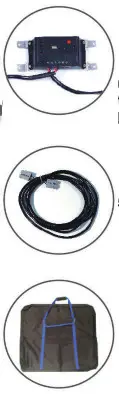 |
Solar Regulator/ Controller(Manages voltage delivered to the battery, ensuring your battery is safe) |
| 5m Extension Lead with Plugs and Battery Clips | |
| Heavy Duty Protective Carry Bag |
SOLAR BLANKET SPECIFICATIONS
| Rated Max Romer (PM) | 160W ( 2X8OW ) |
| Open-Circuit Vo”.age (VOC) | 21.6V |
| Short Circuit Current (ISC) | 9.43A |
| Maximum Power Voltage(Vmp) | 18V |
| Maximum Power Current (Imp) | 8.9A |
| Max System Voltage | 1000V |
| Series Fuse Rating | 15A |
| amensicns | 770 x 670 x trim |
| Weight | 13kg |
- Highly efficient monocrystalline modules in the solar panel guarantee efficient charging.
- When the 160W folding solar panel is folded, its space-saving and portable; when the folding solar kit is open, it has a large solar cell area, providing a good consistent charge.
- The regulator is designed to protect the battery from overcharging, as well as shod circuiting.
- Specially designed support legs enable the 160W folding solar panel to stand on rough and at the desired angle for direct sun exposure.
OPERATION INSTRUCTIONS
The 160W Folding Solar Panel will perform at its peak when the monocrystalline cells are angled directly towards the sun.
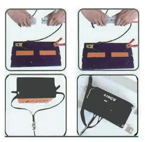
CONNECTING YOUR SOLAR PANEL
- With the panel setup facing directly towards the sun, connect the positive and negative clips to your
- Always connect the battery clips to the battery first, before connecting to the solar panel The battery indicator on the solar controller will then illuminate.
 DISCONNECTING & STORING YOUR SOLAR PANEL
- Disconnect the solar panel from the aligator clips before removing the battery clips off the battery.
- Roll the wire neatly into the space behind the solar panel, make sure not to twist or kink the wiring in an unnatural way.Note: Never store your solar panel with the battery wire connected to the panel.
TIP
- For optimal performance throughout the day, set the panel to approximately 30° from the ground. The range between 10° and 40° will gain the best power absorption across the course of the day.


SOLAR PANEL CONTROLLER
| System voltage | 12V (Auto) | Low voltage protection | 10. N |
| Rated current | 10A | Low voltage reconnecting | 12.6V |
| No-load loss | s12 mA (USB disconnect) | Overloading | ≥1.2’rated current, the 60s≥1.5’rated current, 10s≥1.8’rated current,0.2s |
| Charging mode | PWM | USB output | 5V. 1A |
| Float chargingvoltage | 13.8V | Installing cablessize | AWG24 – AWG12 |
| AbsorptionvoltageCharging/Dischargingcircuit voltage drop | 14. 4V/28.8V(lasting time:2
hours) <0.2V (<0.1\) |
Working temperature Dimensions (L x W x H) Net Weight | -20°C- 50°C119 x 26mm123g |
Features
- Battery indicator show system battery capacity, charging, and discharging state of
- Protection functions such as overcharging, over-discharging, overload, and reverse
- PWM charging increases charging efficiency by 3% to 6%, compared with non-PWM charging.
- The parameters of charging and discharging are preset, so no need to adjust the
- USB output function.
USAGE RECOMMENDATIONS
- As the controller generates heat cluing operation, install in an environment with good ventilation and ample clearance.
- The controller measures the ambient temperature and adjusts bailey charging accordingly, for that reason, place the controller and battery close to each other.
- Always use cables that are rated to or higher than the current output of the controller (I ‘ overloading wires can result in fires and damage to equipment.
- Tha rnntrnSar bac a ennymn rwthita nSa inciria If rem Minn is rani lined (tin Ind Ma nneiliva nnla
INSTALLATION
- Make sure the installation site accords with safety stipulations and is clear of flammable or explosive, or corrosive gases and dust, etc.
- Prepare all the installing tools and cables. Suggest you choose the appropriate multi-core cables to ensure the current density is 54A/mm2 so as to reduce cable voltage drop.
- Putting the controller on a vertical surface, and free space of 10cm on all sides must provide for better heat dissipation.
- Connect the battery to the controller first. After correct connection, check the battery indicator on the controller. If the indicator is not turned on, check whether the connection is right.
- Connect solar panels to the controller. If there is sunlight illuminating the solar panel, battery indicators flash which means the connection is right, otherwise is incorrect.
- Connect the load to the controller. Make sure there’s no reverse polarity connection, red for (+) polarity, black for (- ) polarity.
| Disassembly: To avoid accidents, please dismantle the connection in the following order: solar panels, battery, and load. |
OPERATION
- Charging and display: After the controller is connected correctly if the battery indicators are not illuminating, it means sunlight is weak or none. And if the battery indicators are illuminating from 1-4 LED lights, it means the battery is charged by the controller. When the 4 LEDs light up and the load indicator flashes, it means the battery is in float charging mode, which makes the battery at full charging state to lengthen the longevity of the battery.
- Battery capacity and display: When the battery indicator is red and flashing, to protect the battery the load function WIL is switched off and the load indicator will on green and flash.
| Batterycapacity state | Full charged | 75% | 50% | 25% | Low battery disconnect |
| Indicator | 4 leds | 3 leds | 2 leds | 1 leds | Red & flashing |
- Load indicator: When the load indicator is green and flashing, the load function is switched off.
| Load state | starting | shutting overload protection |
| Indicator | green on | green off green & flashing quickly |
Controller switch is to switch on/off the USB and DC output, if it turn on, the load indicator will turn on a green light, if it is turn off, the green light will turn off.
WORKING MODE
Normal controlling mode: no light control and timing control function used as a normal controller.
FAULTS AND REMEDIES
- Only 1 red battery indicator flashes mean capacity is low. When battery voltage recovers, the controller switches on load automatically.
- Load indicator flashes slowly mean controller output overloading. After removing the redundant load, the controller clears overload protection within 3 minutes.
- The battery indicator doesn’t flash means the solar panel isn’t connected correctly. Make sure the solar panel is correctly and firmly connected.
- If all indicators are off, check whether the fuse of the controller is burnt. If burnt, make sure connections among the solar panel, battery, and load are correct.
QUALITY ASSURANCE
Please read the following instructions carefully. Free guarantee service will not be provided to the said equipment if
- It has been installed and operated otherwise than in accordance with the instructions
- Any unauthorized repair or modification has been carried out on the unit.
- It has been damaged through natural calamities.
- It has been damaged through transportation or storage.
- Batch numbers, serial numbers, or identification marks are manipulated or are
- Load connected has been damaged due to incorrect, reversed connection as the controller is equipped with solar panel and battery to reverse connection protection.
- It has been used to control the power generated from any other type of device such as a Gasoline Generator rather than a solar panel to charge a lead acid battery.
TROUBLESHOOTING
| SYMPTOMS | CAUSES AND SOLUTIONS |
| Battery Indicator does not light up when Solar Panel is in direct sunlight. | Check to make sure the connection between the battery and the controller is correct, the circuit is normal, and the battery/controller is healthy |
| Battery Indicator LED flashing rapidly. | overload. After removing the excess load, the B controller will turn off the overload protection within 3 minutes. |
| Battery Indicator LED is off, battery voltage the battery and the controller is correct, the is sufficient, but there is no output. Check to make sure the connection between the circuit is normal, and the battery/controller is healthy | |
| The Battery Indicator LED is off. | Check to make sure the connection between the battery and the controller is correct, the circuit is normal, and the battery/controller is healthy. |
| Battery Indicator LED flashing rapidly and nobattery output. | Overload. After removing the excess load, the controller will turn off the overload protection within 3 minutes |
| The Load Indicator LED is flashing slowly and isnot receiving power | Short circuit of Ioad.After solving the load short-circuit malfunction, the controller will turn off short circuit protection within 5 minutes. |
The Load Indicator LED is flashing rapidly and the load is not being powered.
 report this ad report this ad
|
After solving the load short-circuitmalfunction, the controller will turn off short circuit protection within 5 minutes. |
| The Load Indicator LED is on but, the load is not powered. | Check to make sure all connections are strong and reliable. |
| Other | Check to make sure all connections are strong and reliable. Ensure battery and/or load is 12V |
[xyz-ips snippet=”download-snippet”]